
The automotive industry stands as a cornerstone of modern manufacturing, with its demands for high-performance, complex, and reliable components driving continuous innovation in production techniques. Among these, lost wax casting, or investment casting, has secured a critical position. This process, renowned for its ability to produce net-shape or near-net-shape parts with exceptional dimensional accuracy and surface finish, is uniquely suited to meet the stringent requirements of automotive engineering. The method’s capability to cast intricate geometries from a wide range of alloys—including steel, aluminum, and superalloys—with minimal machining allowance makes it economically and technically vital for producing powertrain components, chassis parts, and decorative elements. The evolution of lost wax casting is inextricably linked to the advancement of the automotive sector, pushing the boundaries of what is possible in metal component design and manufacturing.
Historical Evolution and Foundational Principles
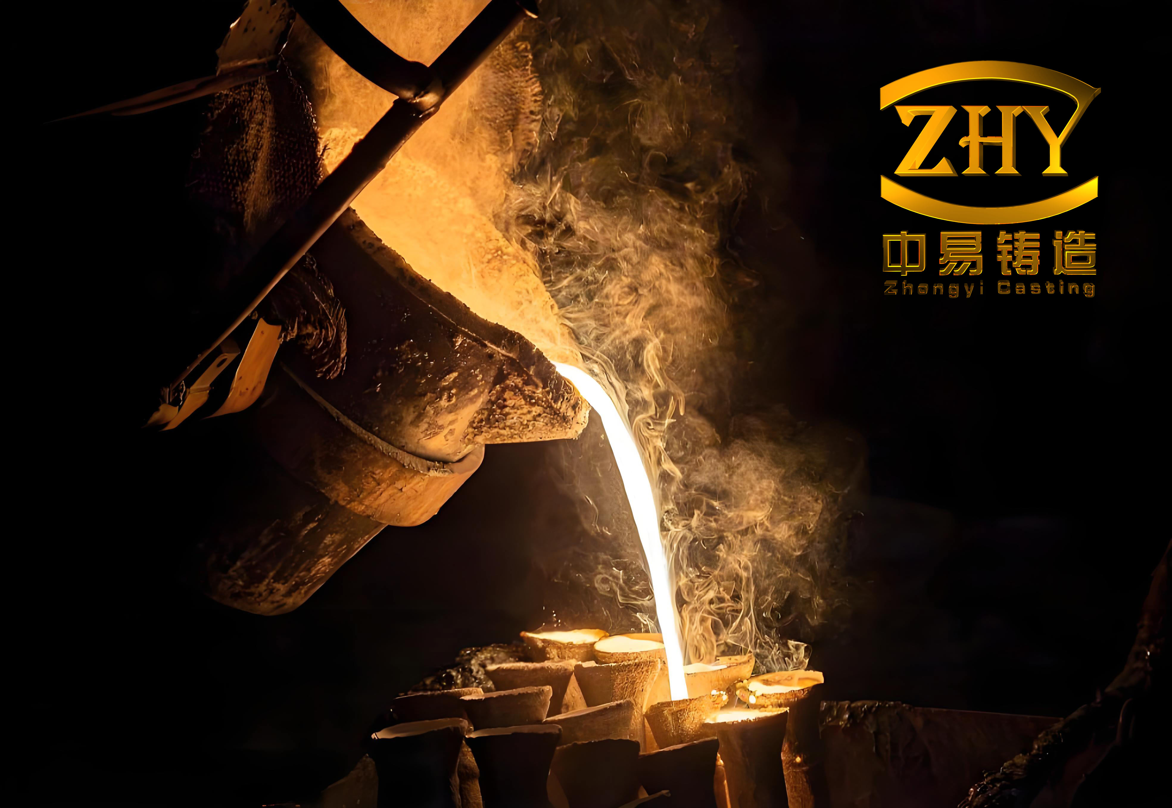
The origins of lost wax casting are ancient, with early examples dating back millennia. However, its modern industrial incarnation began to take shape in the mid-20th century. The foundational principle remains elegantly simple yet requires meticulous control: a disposable wax pattern is created, assembled into a cluster, coated with a refractory ceramic shell, melted out, and the resulting mold is filled with molten metal. The key advantage for automotive applications is the replication of fine details and the excellent metallurgical properties achievable, as the mold is preheated and the metal fills it under controlled conditions, often with the aid of vacuum or pressure.
The basic process flow for lost wax casting can be summarized by the following sequential steps, each critical to final quality:
- Pattern & Gating Design: Creation of a master die and design of the wax injection system (gates, runners, risers).
- Wax Injection & Assembly: Production of wax replicas and their assembly onto a central wax sprue to form a “tree.”
- Shell Building: Repeated dipping of the wax tree into ceramic slurry, stuccoing with refractory sand, and drying to build a robust shell.
- Dewaxing & Firing: Removal of the wax (e.g., by autoclave or flash fire) and high-temperature firing of the ceramic shell to develop strength and remove residues.
- Melting & Pouring: Melting of the alloy and pouring into the preheated ceramic mold.
- Knock-out, Cut-off & Finishing: Removal of the ceramic shell, separation of individual castings from the tree, and finishing operations (grinding, shot blasting, heat treatment, inspection).
Critical Process Variables and Their Impact on Casting Integrity
The quality of a component produced via lost wax casting is not a matter of chance but a direct consequence of controlling a multitude of interacting variables. Four pillars define this control: alloy metallurgy, wax pattern quality, ceramic shell performance, and the dynamics of the pouring process.
1. Alloy Composition and Melt Quality Control
The metallic alloy is the literal substance of the final part. Its chemical composition and purity govern mechanical properties, castability, and defect formation. Impurities, particularly gases like hydrogen, oxygen, and nitrogen, are detrimental. During solidification, these gases may precipitate at grain boundaries or within the dendrite mesh, leading to porosity, hot tearing, and reduced mechanical integrity. The susceptibility to hot tearing, a catastrophic defect in lost wax casting, is highly sensitive to specific element ranges.
The effect of key elements in steel-based alloys for automotive lost wax casting can be modeled. For instance, the tendency for hot cracking (HC) can be expressed as a function of composition and solidification range:
$$ H_C \propto \frac{\Delta T_S}{\sigma_{TS} \cdot \delta} \cdot f(C, S, P…) $$
where \(\Delta T_S\) is the solidification range, \(\sigma_{TS}\) is the tensile strength at high temperature, and \(\delta\) is the ductility in the mushy zone. The function \(f(C, S, P…)\) represents the influence of individual elements. A summary is provided below:
| Element | Concentration Range (wt.%) | Primary Effect on Hot Tearing & Castability | Mechanism |
|---|---|---|---|
| Carbon (C) | < 0.2 | Increases susceptibility | Widens solidification range, lowers high-temperature strength. |
| ~0.2 | Optimum resistance | Balances strength and ductility in the mushy zone. | |
| 0.2 – 0.5 | Decreases susceptibility | Narrows freezing range, increases early strength. | |
| > 0.5 | Increases susceptibility | Promotes carbide formation and segregation. | |
| Sulphur (S) | Any (>0.01) | Strongly increases susceptibility | Forms low-melting-point FeS films at grain boundaries. |
| Phosphorus (P) | Any (>0.015) | Increases susceptibility | Increases solidification range, promotes segregation. |
| Manganese (Mn) | 0.5 – 1.2 | Decreases susceptibility | Neutralizes sulphur by forming higher-melting-point MnS. |
| Silicon (Si) | 0.2 – 0.6 | Slightly decreases susceptibility | Improves fluidity, acts as a mild deoxidizer. |
| Aluminum (Al) (in steel) | > 0.05 | Can increase susceptibility | Powerful deoxidizer; excess can lead to alumina inclusions. |
Melt quality is ensured through degassing (using argon purging or vacuum melting) and effective slag removal. The cleanliness of the melt, often quantified by inclusion counts or gas content (e.g., [H] < 2 ppm for critical aluminum castings), is paramount. The famous Chvorinov’s rule also guides the design of risers in lost wax casting to prevent shrinkage porosity:
$$ t_s = B \left( \frac{V}{A} \right)^n $$
where \(t_s\) is the local solidification time, \(V\) is the volume, \(A\) is the surface area, \(B\) is the mold constant, and \(n\) is an exponent (~2). A higher \(V/A\) ratio indicates a slower cooling section requiring a riser.
2. Wax Pattern Quality and Dimensional Fidelity
The wax pattern is the geometric blueprint for the final metal part. Its dimensional accuracy and surface finish are directly transferred to the ceramic shell and, ultimately, the casting. Achieving this requires precise control over wax properties and injection parameters. The wax is typically a blended polymer (e.g., paraffin, microcrystalline wax, esters) with modifiers to control viscosity, shrinkage, and strength.
Pattern quality is compromised by several factors, as detailed in the following table. The linear shrinkage of wax (\(\alpha_w\)) is a critical parameter, influenced by temperature and pressure:
$$ \alpha_w = \beta_{th} \cdot \Delta T + \beta_{pr} \cdot \Delta P + \gamma_{ag} \cdot t $$
where \(\beta_{th}\) is the thermal contraction coefficient, \(\Delta T\) is the temperature drop from injection to room temperature, \(\beta_{pr}\) is the pressure-dependent shrinkage coefficient, \(\Delta P\) is the pressure change, and \(\gamma_{ag}\) is an aging factor over time \(t\).
| Factor | Consequence on Pattern/Wax | Resulting Casting Defect | Corrective/Preventive Measures |
|---|---|---|---|
| Wax Temperature Too High | Increased volumetric shrinkage, pattern distortion. | Overall size reduction, warpage, potential hot tears. | Maintain injection temp within ±1°C of optimal (e.g., 56-58°C). |
| Wax Temperature Too Low | Poor flow, incomplete filling, high viscosity. | Non-fills, cold shuts, rough surface finish. | As above; ensure uniform melt temperature. |
| Injection Pressure Too Low | Inadequate packing, high shrinkage. | Surface sinks, internal porosity (mirrored from wax). | Optimize pressure profile (e.g., 3-5 MPa, with pack/hold phase). |
| Injection Pressure Too High | Die flash, pattern stress, entrapped air. | Fins on casting, pattern cracking, blister defects. | Use minimum pressure for full packing; optimize venting. |
| Insufficient Hold Time | Pattern shrinks away from die before gate seals. | Dimensional undersize, distortion. | Calibrate hold time until gate freezes (often 45-60s). |
| Contaminated/Recycled Wax | Non-homogeneous composition, lower strength. | Pattern distortion, shell cracking, poor surface finish (veining, buckles). | Implement strict wax reclamation process (filtering, blending with 20-30% new wax). |
| Improper Die Design (draft, gating) | High ejection stress, air entrapment. | Pattern damage, drag marks, laminar defects. | Apply adequate draft (>1°); design gates for laminar fill and easy removal. |
3. Ceramic Shell System: Engineering the Mold
The ceramic shell is the engine of the lost wax casting process. It must withstand the thermal shock of molten metal, resist metallostatic pressure, maintain dimensional stability, and allow gases to escape. Its properties are engineered through the choice of binder, refractory flour, and stucco at each layer.
The dominant binder systems are:
Silica Sol (Colloidal Silica): Provides excellent surface finish and high-temperature shell strength. The bonding mechanism is based on the formation of Si-O-Si bridges during drying and firing.
Sodium Silicate (Water Glass): A lower-cost alternative, hardened by chemical reaction (e.g., with ammonium chloride or Al3+ salts). It offers faster build-up but generally lower refractoriness and surface quality.
Hybrid Systems: Combining a silica sol primary coat with subsequent silicate-based backup coats is common to optimize cost and performance.
The shell’s green strength (after drying) and fired strength are critical. The fired strength, especially at pouring temperature (\(\sigma_{shell}\)), can be modeled as a function of its composition and porosity (\(\phi\)):
$$ \sigma_{shell} \approx \sigma_0 \cdot (1 – \phi)^m \cdot \exp\left(-\frac{E_a}{RT}\right) $$
where \(\sigma_0\) is the intrinsic strength of the ceramic bridge network, \(m\) is a constant, \(E_a\) is the activation energy for sintering, \(R\) is the gas constant, and \(T\) is the firing/pouring temperature. Shell permeability (\(k\)), vital for venting gases, is given by the Carman-Kozeny equation:
$$ k = \frac{\phi^3}{K \cdot S_v^2 \cdot (1-\phi)^2} $$
where \(K\) is the Kozeny constant and \(S_v\) is the specific surface area of the refractory particles. A comparison of shell materials and their effects is below:
| Shell Component | Common Materials | Key Properties & Role | Impact on Casting Quality |
|---|---|---|---|
| Primary Coat Binder | Colloidal Silica, Ethyl Silicate | High chemical purity, fine particle size for surface replication. | Directly determines casting surface finish (Ra). Low Na2O prevents metal-mold reaction. |
| Back-up Coat Binder | Sodium Silicate, Colloidal Silica | Builds thickness, provides structural strength. | Governs overall mold strength, resistance to deformation/bulging during pour. |
| Refractory Flour (Slurry) | Fused Silica, Zircon, Aluminosilicates | Sets fired strength, thermal expansion, and chemical stability. | Fused silica offers low thermal expansion for crack resistance. Zircon provides high refractoriness for steel castings. |
| Stucco (Sand) | Alumina-Silica Sand, Zircon Sand, Mullite | Provides a key for layers, controls permeability, and thickness. | Coarser stucco increases permeability. Angular sands improve interlayer bonding. Choice affects shell drainability and build-up rate. |
| Additives | Wetting Agents, Anti-foam, Fibers (e.g., nylon) | Improve slurry application, reduce bubbles, enhance green strength. | Wetting agents ensure complete pattern coverage. Fibers reduce shell cracking during dewax and handling. |
Shell failure often follows a Weibull distribution due to its brittle ceramic nature, where the probability of failure \(P_f\) at stress \(\sigma\) is:
$$ P_f = 1 – \exp\left[-\left(\frac{\sigma}{\sigma_0}\right)^m\right] $$
where \(m\) is the Weibull modulus (higher is more reliable) and \(\sigma_0\) is the characteristic strength.
4. Pouring Dynamics: Filling and Solidification Control
The final act of transferring molten metal into the ceramic mold encapsulates numerous physical phenomena—fluid flow, heat transfer, and solidification—that determine internal soundness. The two most critical parameters are pouring temperature (\(T_p\)) and pouring speed/filling time (\(t_f\)).
Pouring temperature is a compromise: too low leads to misruns and cold shuts; too high increases gas dissolution, metal-mold reaction, and gross shrinkage. An optimal range is typically 30-100°C above the alloy’s liquidus temperature (\(T_L\)), depending on section thickness:
$$ T_p = T_L + \Delta T_{superheat} $$
where \(\Delta T_{superheat}\) is chosen based on part geometry and thermal modulus (\(V/A\)).
Pouring speed dictates the fluid flow regime. The goal is laminar filling to avoid turbulence, which entraps mold gases and creates oxide bifilms. The fundamental Bernoulli and Reynold’s number (\(Re\)) principles apply. The velocity \(v\) at the gate should be controlled:
$$ v = \frac{Q}{A_g} = \mu \sqrt{2gh} $$
where \(Q\) is the volumetric flow rate, \(A_g\) is the gate cross-sectional area, \(\mu\) is the discharge coefficient, \(g\) is gravity, and \(h\) is the effective metal head. To ensure laminar flow in the mold cavity, \(Re\) should be below a critical value (often ~2000 for metal in a channel):
$$ Re = \frac{\rho v D_h}{\eta} $$
where \(\rho\) is density, \(D_h\) is the hydraulic diameter, and \(\eta\) is the dynamic viscosity. Simulation (e.g., using ProCAST, Flow-3D) is indispensable for visualizing these effects, as seen in automotive components like turbocharger wheels or pump impellers where improper gating leads to mistruns or oxide entrainment.
The thermal gradient (\(G\)) and solidification rate (\(R\)) govern the microstructure. The product \(G \cdot R\) influences grain size, while \(G/R\) controls the morphology (columnar vs. equiaxed). In directional solidification for single-crystal turbine blades (an aerospace application of lost wax casting), maximizing \(G\) is key. For most automotive castings, promoting a fine, equiaxed grain structure through low \(G/R\) is desirable for isotropic properties.
Comparative Analysis and Industry Challenges
The global landscape of automotive lost wax casting reveals a significant performance gap between general producers, domestic leaders, and international front-runners. This gap stems from systemic differences in approach, investment, and innovation culture.
| Aspect | General Industry Level | Domestic Advanced Level | International Benchmark Level |
|---|---|---|---|
| Scale & Economics | Fragmented, small-scale production; low-profit margins. | Consolidated, larger facilities with better economies of scale. | Highly automated, mega-foundries serving global OEMs; optimized for high-volume production. |
| Technological Investment | Low; reliance on older equipment. Process control is manual or experience-based. | Moderate; adoption of advanced melting (induction), robotics for shell dipping, basic process monitoring. | High; integrated Industry 4.0 systems: real-time process sensors, adaptive control loops, digital twins for process optimization. |
| Quality Metrics | |||
| – Surface Finish (Ra) | 3.2 – 6.3 μm | 1.6 – 3.2 μm | 0.8 – 1.6 μm (achievable with precise primary coats) |
| – Dimensional Tolerance (CT) | CT7 – CT9 per ISO 8062 | CT5 – CT7 | CT4 – CT6 (enabling true net-shape assembly) |
| – Internal Soundness | Acceptance based on workability; significant scrap/repair rates. | X-ray inspection standard; controlled porosity levels. | 100% digital radiography (DR) or CT scanning for critical parts; near-zero defect philosophy (Six Sigma). |
| Sustainability Footprint | High energy consumption/ton; limited waste recycling; high emissions. | Implementing energy recovery, basic sand/wax reclamation. | Closed-loop systems: near-100% alloy recycle, thermal oxidizers for VOC, zero-discharge water treatment, shell aggregate reuse in construction. |
| R&D & Innovation | Reactive, customer-driven modifications; minimal fundamental research. | Focused on process improvement and material substitution. | Proactive; dedicated R&D for new alloys (e.g., high-strength aluminum, MMCs), binder systems, and additive manufacturing integration. |
The core challenges hindering widespread advancement in lost wax casting include: a deeply ingrained reliance on empirical knowledge over data-driven science; capital constraints limiting adoption of automation and advanced quality control equipment; a shortage of skilled metallurgists and process engineers; and market pressures that prioritize low initial cost over total lifecycle cost and performance, disincentivizing investment in premium processes.
Strategic Directions and Future Development Trends
The future of lost wax casting in the automotive sector is defined by several convergent trends, all pointing towards greater precision, integration, intelligence, and sustainability.
1. Product Strategy: “Precise, Optimal, Light, Green”
Precise & Optimal: The drive is towards zero-defect manufacturing and dimensional stability that eliminates secondary machining. This involves statistical process control (SPC) for every variable and advanced non-destructive testing (NDT). The goal for surface finish is moving towards Ra < 1.6 μm as a standard for visible components.
Lightweighting: This is perhaps the most powerful trend. Lost wax casting enables complex, topology-optimized designs that reduce weight while maintaining stiffness. The objective function in design optimization often includes minimizing mass (\(m\)) subject to stress (\(\sigma\)) and deflection (\(\delta\)) constraints:
$$ \text{Minimize: } m = \int_V \rho \, dV $$
$$ \text{Subject to: } \sigma_{max} \leq \sigma_{yield}/SF, \quad \delta_{max} \leq \delta_{allowable} $$
This leads to organic, thin-walled structures with integrated ribs and hollow sections, perfectly suited for the process’s capabilities.
Green Foundry: Sustainability metrics are becoming key performance indicators. This includes reducing the Process Mass Intensity (PMI) and increasing the Material Circularity Indicator (MCI):
$$ PMI = \frac{\text{Total Mass in Process (kg)}}{\text{Mass of Finished Casting (kg)}} $$
$$ MCI = \frac{\text{Recycled / Reused Input + Recyclable Output}}{\text{Total Material Throughput}} \times 100\% $$
The target is to minimize PMI and maximize MCI through comprehensive recycling of wax, alloy scrap, and ceramic materials.
2. Process & Technological Integration
The evolution is towards a fully integrated and digital lost wax casting cell:
Additive Manufacturing (AM) Integration: Using stereolithography (SLA) or binder jetting to produce direct ceramic shells or soluble cores for impossible internal geometries, radically reducing lead time for prototypes and complex parts.
Advanced Process Simulation: Moving beyond simple filling and solidification to multi-physics simulations coupling fluid flow, stress evolution (predicting distortion), and microstructure prediction (e.g., using CALPHAD-based models).
Robotics & Automation: Robotic arms for consistent shell dipping, pouring, and finishing. Machine vision for in-line inspection of wax patterns and finished castings.
Smart Foundry Concepts: Embedding IoT sensors throughout the process to create a digital thread. Real-time data on slurry viscosity, shell drying rates, furnace temperatures, and pouring parameters are fed into a central AI/ML platform for predictive quality control and adaptive process adjustment.
3. The Rise of the Digital Thread and Computational Design
Computer-aided engineering (CAE) is no longer just a tool but the backbone of modern lost wax casting. The digital thread connects:
CAD/Generative Design: Creating optimized geometries for weight and performance.
CAE Simulation: Validating manufacturability (filling, solidification, stress) and performance (FEA under load).
Process Planning (CAPP): Automatically generating gating system designs, selecting process parameters based on historical data and simulation results.
Manufacturing Execution (MES): Controlling the actual production floor based on the digital plan.
Quality Assurance: Comparing 3D scan data of the finished casting directly to the original CAD model for deviation analysis.
This closed-loop, data-driven approach ensures first-pass success, reduces development time, and guarantees consistent quality in high-volume automotive lost wax casting production.
Conclusion
Lost wax casting remains a dynamic and indispensable manufacturing process within the automotive industry’s ecosystem. Its unique value proposition—the ability to produce high-integrity, complex, and lightweight metal components—aligns perfectly with the industry’s relentless pursuit of efficiency, performance, and innovation. The journey from a craft-based practice to a sophisticated, computer-integrated manufacturing science is well underway. The future of automotive lost wax casting lies in embracing the synergy between advanced materials science, digitalization, and sustainable manufacturing principles. By doing so, it will continue to evolve from a method of making parts to a strategic enabler of next-generation automotive design, supporting the transition towards electric vehicles, autonomous systems, and a circular economy. The ongoing research and development in alloy behavior, wax and shell chemistry, process modeling, and automation are not merely incremental improvements but fundamental steps towards realizing the full potential of this ancient yet perpetually modern casting technique.