
In the realm of advanced manufacturing, precision lost wax casting, also known as investment casting, stands out for its ability to produce complex, near-net-shape metal parts with excellent dimensional accuracy and surface finish. This process is particularly valuable for high-performance alloys like 42CrMo, a medium-carbon alloy steel renowned for its high strength, toughness, and hardenability. Through precision lost wax casting, we can fabricate intricate components such as engine rocker arms, which demand stringent mechanical properties and minimal defects. This article delves into the comprehensive production methodology for a 42CrMo exhaust valve rocker arm via precision lost wax casting, detailing every critical step from pattern-making to heat treatment, supported by empirical data, tables, and relevant mathematical models.
The component in question is an exhaust valve rocker arm for a diesel engine, with a mass of approximately 250 grams, an average wall thickness of 4 mm, and a minimum thickness of 2.6 mm. It features a blind hole, adding to the geometric complexity. The material specification adheres to GB3077-1999, requiring quenched and tempered treatment to achieve a tensile strength of 830–870 MPa and a hardness of 250–290 HBS. Defect levels must conform to Class B of HB5001-92, with controlled decarburization depth. Achieving these specifications through precision lost wax casting necessitates meticulous control over each process parameter, as outlined below.
The initial phase involves casting process design and simulation. We utilized casting simulation software to optimize the gating and feeding system. The simulation aimed to minimize defects such as shrinkage porosity and misruns, ensuring uniform filling and solidification. For the rocker arm, the precision lost wax casting layout comprised a cluster of 12 patterns arranged at a 30-degree inclination. Molten metal is introduced through a sprue, distributed via runners, and enters the cavities through ingates. This configuration promotes directional solidification and reduces turbulence. The modulus method, based on Chvorinov’s rule, guides the design of feeding systems. The solidification time t is given by:
$$ t = B \left( \frac{V}{A} \right)^2 $$
where V is the volume of the casting section, A is its surface area, and B is a constant dependent on mold material and casting conditions. For the thin-walled rocker arm, with a high surface-area-to-volume ratio, solidification is rapid, necessitating careful control of pouring parameters to avoid cold shuts.
Following simulation, the precision lost wax casting process proceeds to pattern fabrication. We employ commercial wax (WM36-1) to produce the sacrificial patterns of both the component and the gating system. A mold release agent, specifically atomized silicone oil, ensures easy demolding. The injection molding parameters are critical to achieving dimensional stability and surface quality of the wax patterns. Key parameters are summarized in Table 1.
| Control Parameter | Value or Range |
|---|---|
| Ambient Temperature | 18–28 °C |
| Mold Temperature | 25–40 °C |
| Wax Cylinder Temperature | 54–58 °C |
| Injection Nozzle Temperature | 56–62 °C |
| Injection Pressure | 2.0–2.5 MPa |
| Holding Time | 20–25 s |
| Demolding Time | 2 s |
| Cooling Time | ≥20 min |
After injection, the wax patterns are assembled into clusters. The assembly must ensure a minimum head distance of 60 mm from the top pattern to the pouring cup and a minimum residual head of 20 mm from the bottom ingate to the sprue base. Patterns are spaced at least 8 mm apart to allow proper coating and drying. All joints are sealed meticulously to prevent shell cracks. The assembled cluster is then cleaned using an emulsified aqueous solution at 24±2 °C to remove any contaminants, enhancing shell adhesion.
The core of precision lost wax casting lies in the ceramic shell building process. A multi-layered shell is constructed to withstand the thermal shock of molten metal. The slurry compositions for each layer are formulated to balance refractoriness, permeability, and strength. Table 2 details the slurry recipes for the primary, secondary, and backup coats.
| Layer | Slurry Composition | Density (g/cm³) | Viscosity (s) |
|---|---|---|---|
| Primary Coat | Silica sol: 15 kg; Fused alumina: 24–28 kg; Wetting agent: 25 mL; Defoamer: 18 mL | 1.80–1.85 | 33–37 |
| Secondary Coat | Silica sol: 18 kg; Zircon flour: 30–32 kg; Wetting agent: 18 mL; Defoamer: 15 mL | 1.68–1.72 | 32±1 |
| Transition Coats | Silica sol: 11 kg; Calcined kaolin: 16–17 kg | 1.65–1.70 | 19±1 |
| Seal Coat | Silica sol: 10 kg; Calcined kaolin: 14–15 kg | 1.81–1.83 | 13±1 |
Each slurry layer is followed by stuccoing with refractory granules of specific mesh sizes to build thickness and create a porous structure for gas escape. The stuccoing sequence and drying conditions are paramount. Drying kinetics can be approximated by Fick’s second law of diffusion, where the moisture content C varies with time t and position x:
$$ \frac{\partial C}{\partial t} = D \frac{\partial^2 C}{\partial x^2} $$
Here, D is the effective diffusivity, dependent on temperature and humidity. Controlled drying environments, as specified in Table 3, prevent cracking or deformation.
| Shell Layer | Stucco Material & Mesh Size | Drying Time (h) | Air Velocity (m/s) |
|---|---|---|---|
| 1 (Primary) | Quartz sand, 50/100 mesh | ≥24 | – |
| 2 (Secondary) | Quartz sand, 40/70 mesh | ≥24 | – |
| 3–6 (Transition) | Calcined kaolin sand, 30/60 to 16/30 mesh | ≥24 | 6–8 |
| Seal | – | ≥12 | – |
Environmental conditions during shell building are maintained at 18–25 °C with relative humidity of 40–70% for primary layers and 20–50% for backup layers. This precision lost wax casting step ensures a robust shell capable of withstanding subsequent dewaxing and firing.
Dewaxing is performed using high-pressure steam autoclaving. The shell is exposed to steam at 0.6–0.75 MPa, with pressure ramping to 0.6 MPa in less than 14 seconds. The total dewaxing time is controlled within 7–8 minutes. The rapid heating causes the wax to expand and melt, flowing out through designated drains. The shell must withstand thermal shock; the stress σ induced can be estimated by:
$$ \sigma = E \alpha \Delta T $$
where E is Young’s modulus of the ceramic, α is the coefficient of thermal expansion, and ΔT is the temperature gradient. Proper shell design minimizes stress concentrations.
Following dewaxing, the ceramic shell is fired to remove residual volatiles and sinter the ceramic, enhancing its strength. Firing is conducted at 850±10 °C for at least 3 hours. The kinetics of binder removal and sintering can be described by Arrhenius-type equations. For instance, the sintering rate often follows:
$$ \frac{dr}{dt} = \frac{A}{r^n} \exp\left(-\frac{Q}{RT}\right) $$
where r is the particle radius, A is a pre-exponential factor, n is an exponent related to the mechanism, Q is the activation energy, R is the gas constant, and T is the absolute temperature. Firing ensures a stable mold ready for metal pouring.
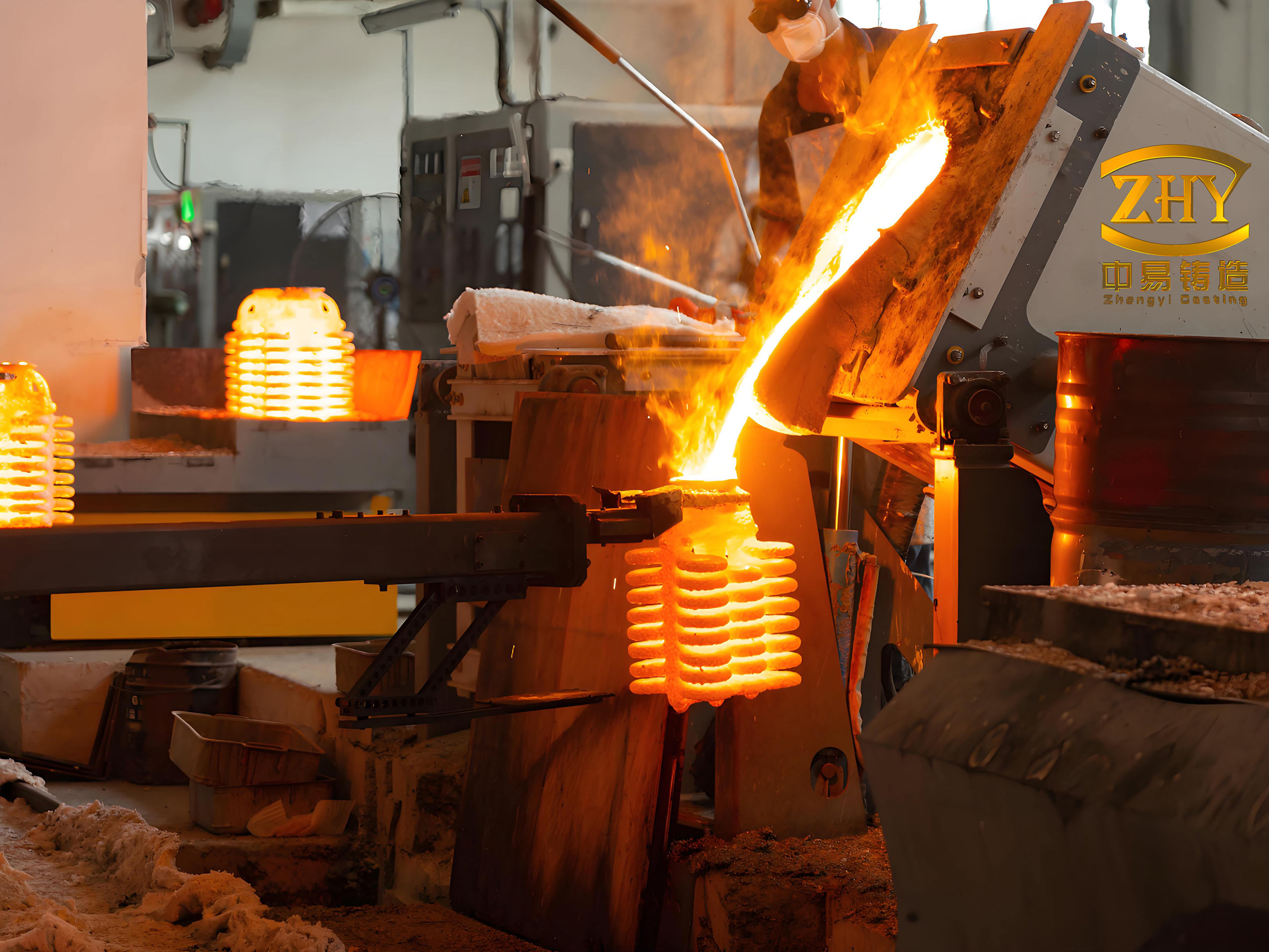
The melting and pouring stage is critical for achieving the desired metallurgical quality. The 42CrMo alloy is prepared according to the chemical composition specified in GB/T 3077-1999. Charge materials are free from oil and rust, and recycled gates are labeled with heat numbers. The target composition is outlined in Table 4.
| Element | Specification (wt%) | Target Charge (wt%) |
|---|---|---|
| C | 0.38–0.45 | 0.42 |
| Si | 0.17–0.37 | 0.34 |
| Mn | 0.50–0.80 | 0.65 |
| Cr | 0.90–1.20 | 1.00 |
| Mo | 0.15–0.25 | 0.18 |
Melting is carried out in a medium-frequency induction furnace (KGYSC-175/3). The superheating temperature and pouring temperature are tightly controlled. For this precision lost wax casting operation, the mold is preheated to 850±10 °C, and the steel is poured at 1580±10 °C using a transfer ladle. The pouring time is restricted to 2–3 seconds to minimize oxidation and temperature drop. The fluidity of molten steel, essential for filling thin sections, can be approximated by:
$$ L_f = k \sqrt{T_{pour} – T_{liquidus}} $$
where Lf is the fluidity length, k is a constant, Tpour is the pouring temperature, and Tliquidus is the liquidus temperature of the alloy. Maintaining high superheat ensures complete mold filling.
After solidification and cooling, the castings are removed from the shell via mechanical vibration and grit blasting. Individual castings are cut from the cluster using abrasive wheels. Any surface defects detected are repaired using tungsten inert gas (TIG) welding with H18CrMoA filler wire, conforming to repair standards. The weld thermal cycle must be controlled to avoid excessive heat-affected zone softening, governed by heat conduction equations.
The next crucial step is heat treatment to achieve the required mechanical properties. The 42CrMo rocker arms undergo quenching and tempering. The heat treatment cycle, derived from experimental optimization, is illustrated in Figure 3. Quenching involves heating to 850±10 °C, holding for 1.5–2 hours to achieve full austenitization, followed by oil quenching. Tempering is performed at 650±10 °C for 1.5–2 hours, then oil cooled. The tempering kinetics can be modeled using the Larson-Miller parameter P for creep and softening:
$$ P = T \left( C + \log t \right) $$
where T is the absolute temperature, t is the time, and C is a constant (often around 20 for steels). This parameter helps predict the resultant hardness and strength after tempering. The final microstructure typically consists of tempered martensite, providing an optimal balance of strength and toughness.
Post-heat treatment, the castings undergo vibratory finishing for surface smoothing. They are processed in a vibratory tumbler with ceramic media and lubricated with kerosene for over 48 hours. This process removes minor surface irregularities and improves fatigue resistance. The final components are cleaned with gasoline and inspected.
To validate the precision lost wax casting process, we conducted thorough quality assessments on production samples. Dimensional checks confirmed conformity to the CAD model. Chemical analysis verified the composition within specified limits. Mechanical testing revealed tensile strengths averaging 850 MPa and hardness values of 270 HBS, meeting the target range. Non-destructive testing via ultrasonic inspection detected no internal flaws exceeding Class B criteria. The process yield, defined as the weight of usable castings relative to total poured weight, was calculated. For a cluster of 12 rocker arms with a total weight (including gating) of 10.8 kg, each casting weighs about 244 grams, yielding a casting yield of approximately 27.1%. This yield is typical for precision lost wax casting of complex thin-walled parts, where extensive gating is necessary for proper feeding.
The success of this precision lost wax casting project is evident from the subsequent batch production. Since implementation, monthly delivery volumes have reached 30,000 pieces each for exhaust and intake rocker arms, totaling over 600,000 parts within ten months. This demonstrates the robustness and scalability of the defined process parameters.
In conclusion, precision lost wax casting is a highly effective method for manufacturing high-integrity 42CrMo alloy components. By integrating computational simulation, meticulous control of pattern-making, shell building, dewaxing, melting, and heat treatment, we achieved consistent production of exhaust valve rocker arms meeting rigorous specifications. The numerous tables and formulas presented underscore the scientific approach underlying this precision lost wax casting operation. Future work may focus on further optimizing the gating design to improve yield and exploring additive manufacturing for pattern production to enhance flexibility. Nonetheless, the current methodology provides a reliable framework for precision lost wax casting of similar high-performance steel parts.