
The gas turbine stands as the core of 21st-century power equipment, representing the pinnacle of power generation technology and advanced manufacturing. Its applications span critical sectors from aerospace and marine propulsion to civilian power generation and pipeline transmission, making the mastery of its core component manufacturing a strategic imperative. Among these components, the turbine vane carrier is a critical structural element, responsible for supporting and positioning stator vanes within the high-temperature, high-pressure gas path. The development of a robust and reliable manufacturing process for this large-scale, complex steel casting is therefore paramount.
This article details the comprehensive research and development process undertaken for the steel casting of a heavy-duty gas turbine vane carrier. The focus lies on overcoming the significant challenges associated with casting a component of such substantial size, intricate geometry, and stringent quality requirements. The process encompasses every stage from initial structural analysis and process design to melting, heat treatment, and final validation, with a constant emphasis on achieving sound metallurgical integrity and dimensional accuracy.
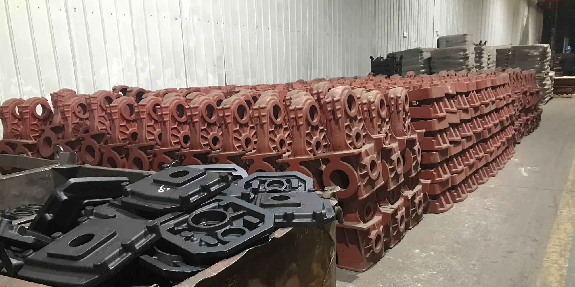
The component in question is a large, ring-shaped structure with significant variations in wall thickness. The maximum wall thickness reaches approximately 446 mm, presenting a major challenge for solidification control and feeding. The material specification is a low-alloy cast steel, similar to G17CrMo5-5, requiring a specific combination of strength, toughness, and high-temperature stability. The key technical hurdles identified at the outset included:
- Preventing shrinkage porosity and macro-shrinkage in the massive wall sections.
- Achieving uniform mold filling to avoid cold shuts and turbulence-related defects.
- Controlling distortion during solidification and subsequent heat treatment.
- Meeting rigorous mechanical property specifications throughout the thick sections.
- Avoiding sand burn-on and penetration in deep, enclosed cavity features.
The success of this steel casting project hinged on a meticulously planned and integrated approach, where foundry工艺, metallurgy, and simulation worked in concert.
Structural Analysis and Foundry工艺 Design Strategy
The first step involved a thorough analysis of the 3D geometry. The vane carrier was essentially a thick-walled cylinder with numerous integral flanges, mounting lugs, and internal channels. Casting the upper and lower halves as a single unit was strategically chosen. This approach offered several advantages for the steel casting process: it simplified core assembly, provided more favorable thermal gradients for directional solidification towards the risers, and improved production efficiency. A horizontal mold joint was selected, with the complex internal profile formed by cores in the cope (upper mold half).
A critical challenge was the presence of deep, recessed pockets in the upper section. During pouring, these areas would become enveloped by hot metal, leading to extreme thermal loading on the sand mold and a high risk of severe burn-on. To mitigate this, custom-fabricated ring-shaped chill inserts, made from steel bar stock, were placed in these regions within the mold. These chills extracted heat rapidly, protecting the sand and ensuring a clean casting surface.
Determination of Process Allowances
Accurate prediction and application of allowances are crucial in steel casting to achieve final machined dimensions. The total linear contraction (shrinkage) for this low-alloy steel was estimated based on empirical data from similar castings, typically ranging between 1.6% and 2.0%. This shrinkage allowance was applied uniformly to the pattern dimensions.
Furthermore, machining allowances were applied to all critical surfaces. For internal surfaces, the allowance was strategically increased to simplify the core geometry, facilitate pattern withdrawal, and aid in the floating of slag during pouring. This resulted in a more planarized internal as-cast surface, which was later machined to the final profile. Anti-distortion (warpage) allowances, though often minimal for symmetric ring geometries, were considered based on previous experience with similar-shaped steel castings to pre-compensate for any predictable stress-relief movement during heat treatment.
Riser and Feed Aid Design: The Core of Soundness
The central challenge in this steel casting was ensuring the soundness of the massive wall sections. Traditional riser design methods, primarily based on modulus calculations, were employed in conjunction with advanced solidification simulation for verification and optimization.
The modulus (M) of a casting section is defined as its volume (V) divided by its cooling surface area (A):
$$ M = \frac{V}{A} $$
For a riser to effectively feed a section, its modulus must be greater than that of the section it is intended to feed. The moduli of key hot spots in the casting, particularly the heavy flange regions, were calculated. For example, considering a cylindrical flange section as a simple approximation:
$$ M_{flange} \approx \frac{\pi r^2 \cdot t}{2\pi r \cdot t + 2\pi r^2} = \frac{r \cdot t}{2t + 2r} $$
(where \( r \) is radius and \( t \) is thickness)
This calculation guided the initial sizing of side risers. The final riser dimensions were then determined by also satisfying the required feed metal volume criterion, ensuring sufficient liquid metal is available to compensate for the total volumetric shrinkage of the feeding zone.
To establish a strong thermal gradient and direct the solidification front towards the risers, feed aids (chills) were strategically placed at the extremities of feeding zones. These chills, typically made of cast iron or steel, accelerate cooling in selected areas, effectively extending the feeding range of the risers and preventing isolated shrinkage in the middle of thick sections. The entire feeding system—comprising elliptical side risers, exothermic sleeve toppings, and strategic chills—was then modeled using MAGMA solidification simulation software. The software’s prediction of shrinkage porosity was used to iteratively refine the design until a sound casting was predicted. The simulation confirmed that the final thermal gradient successfully moved the last point of solidification into the riser necks.
| Element | Specification Range |
|---|---|
| C | 0.15 – 0.20 |
| Si | ≤ 0.60 |
| Mn | 0.50 – 1.00 |
| Cr | 1.00 – 1.50 |
| Mo | 0.45 – 0.65 |
| P | ≤ 0.020 |
| S | ≤ 0.020 |
| Ni | ≤ 0.40 |
| Al | ≤ 0.04 |
Gating System Engineering for Clean Filling
A bottom-gating system was designed to ensure a calm, non-turbulent fill of the mold cavity. Turbulence leads to oxide formation, slag entrapment, and mold erosion, all detrimental to the quality of a premium steel casting. The gating system was designed using fluid dynamics simulation software (GS-100) to optimize the filling pattern.
The system featured a symmetrical layout with multiple ingates to distribute the metal flow evenly. The cross-sectional areas of the sprue, runners, and ingates were proportioned to maintain a pressurised flow and act as a slag trap. The critical parameter is the ingate velocity; too high a velocity causes erosion, while too low risks mistruns. For large steel castings, the target ingate velocity typically lies between 0.4 and 1.0 m/s.
For this casting, with a total poured weight of approximately 87 tonnes requiring two ladles, the fill rate was carefully controlled. The average ingate velocity was calculated and maintained around 0.60 m/s:
$$ v_{ingate} = \frac{Q}{n \cdot A_{ingate}} $$
where \( Q \) is the volumetric pouring rate, \( n \) is the number of ingates, and \( A_{ingate} \) is the cross-sectional area of one ingate. This controlled fill promoted a steady, upward rise of the metal meniscus, minimizing turbulence and ensuring the discharge of any entrapped gases through the mold and core vents.
Melting, Pouring, and Metallurgical Control
The steel for this casting was produced via the Electric Arc Furnace (EAF) and Ladle Furnace (LF) refining route, ensuring precise control over chemistry and low levels of detrimental elements like sulfur and phosphorus (see Table 1). Deoxidation and inclusion shape control were carefully managed to enhance the mechanical properties, particularly toughness. The two-ladle pour required precise temperature coordination. The first ladle was tapped at a higher temperature (~1620°C) to account for heat loss during the extended pouring time, while the second ladle was tapped lower (~1585°C). Pouring was conducted under an argon shield to prevent re-oxidation of the steel stream, a critical practice for high-integrity steel castings.
| Property | Specification |
|---|---|
| Tensile Strength | 490 – 690 MPa |
| Yield Strength (0.2% offset) | ≥ 315 MPa |
| Elongation | ≥ 20 % |
| Impact Energy (Charpy V-notch) | ≥ 27 J at room temperature |
Heat Treatment for Optimal Properties
The as-cast microstructure of this low-alloy steel casting is typically coarse and heterogeneous, with high residual stresses. A tailored heat treatment cycle is essential to achieve the required mechanical properties (Table 2) and stress relief. The cycle was developed based on the principles of phase transformation for this grade.
The selected treatment consisted of a high-temperature austenitization (normalizing) followed by forced-air cooling, and then tempering. Normalizing refines the grain structure formed during solidification. The forced-air cooling rate is faster than still-air cooling, promoting the formation of a finer, stronger bainitic microstructure rather than softer ferrite-pearlite. The subsequent tempering process relieves stresses from cooling, improves toughness, and stabilizes the microstructure. A typical thermal cycle is illustrated below:
| Stage | Temperature Range | Hold Time (approx.) | Cooling Method |
|---|---|---|---|
| Normalizing (Austenitization) | 900°C – 960°C | > 12 hours (for full through-thickness heating) | Forced Air |
| Tempering | 670°C – 740°C | > 12 hours | Furnace Cool |
Heating and cooling rates were controlled (e.g., ≤120°C/h) to prevent thermal shock and distortion. Metallographic examination of test coupons attached to the casting confirmed a uniform, fine-grained microstructure of tempered bainite and ferrite, which delivers an excellent balance of strength and toughness required for the demanding service conditions of a gas turbine.
Welding and Repair Strategy
Despite meticulous process control, minor, acceptable surface discontinuities may be identified during inspection. The high carbon equivalent (Ceq > 0.6) of this steel makes it susceptible to hydrogen-induced cracking during welding. A strict repair welding procedure was established, involving:
- Use of low-hydrogen electrodes and strict baking protocols.
- Pre-heating and interpass temperature control within a specified range (e.g., 150-300°C).
- Employing a temper-bead or hot-pass welding technique for intermediate layers to refine the heat-affected zone (HAZ) microstructure of previous welds.
- Controlling heat input per pass and ensuring adequate weld bead overlap.
- Performing post-weld heat treatment (PWHT) when required by the repair depth, to restore toughness and relieve stresses.
This controlled approach ensured that any necessary repairs did not compromise the integrity of the final steel casting.
Quality Validation and Conclusions
The implemented process was validated through the successful production of prototype castings. Non-destructive testing (NDT) including radiographic (RT) and ultrasonic (UT) examination confirmed the soundness of the thick sections, with no major shrinkage defects detected. Dimensional inspections verified that the casting was within the specified machining allowances. Mechanical tests performed on coupons from the casting body met all specification requirements, demonstrating the efficacy of the heat treatment cycle.
In conclusion, the successful development of this heavy-duty gas turbine vane carrier steel casting demonstrates a holistic engineering approach. Key insights and achievements include:
- The integrated use of modulus calculations and solidification simulation is indispensable for designing effective feeding systems for large, thick-walled steel castings, ensuring sound internal quality.
- Strategic use of chills—both for controlling local solidification and preventing mold defects—is a critical tool in complex steel casting工艺.
- A controlled bottom-gating system, engineered via fluid flow simulation, is essential for achieving a clean fill and minimizing turbulent defects.
- The heat treatment cycle, specifically normalizing with forced-air cooling followed by tempering, is highly effective for achieving the desired strength-toughness combination in low-alloy, heavy-section steel castings.
- A rigorous, procedure-based approach to welding and repair is mandatory for maintaining the quality of high-carbon equivalent steel castings.
This comprehensive methodology not only ensured the quality of a critical component but also enhanced the overall yield and cost-effectiveness of the steel casting process, providing a reliable manufacturing route for this advanced power generation component.