
The seamless and safe operation of a railway network hinges on the integrity of its most fundamental components, many of which operate unseen. Among these critical elements are bridge bearings, the structural interfaces that transfer loads from the superstructure to the substructure while accommodating movements caused by thermal expansion, live loads, and creep. In the mid-20th century, a common design for handling significant rotations and translations in railway bridges was the rocker bearing, a robust assembly primarily fabricated from large-scale steel castings. These components, celebrated for their strength and ability to be formed into complex shapes, were the workhorses of their era. However, decades of intensified service under heavier axle loads and higher speeds have exposed the vulnerabilities of aging steel castings in these assemblies. Phenomena such as excessive permanent displacement, seized movement, and shear failure of connecting pins have become prevalent, transforming a once-reliable component into a critical point of failure that jeopardizes structural stability and operational safety. This treatise, drawn from direct professional experience, delves into the intricate engineering and execution of replacing these deteriorated steel castings—specifically, cast steel rocker bearings—on an operational mainline railway, a high-stakes operation where engineering precision meets the unforgiving timetable of rail traffic.
The project in focus involved a major double-track railway bridge spanning a navigable canal, constructed in the early 1970s. The superstructure consisted of pre-stressed concrete T-beams and steel through-truss girders. The bearings for the concrete spans were the cast steel rocker type. Inspection campaigns revealed that eight rocker bearings on the T-beams showed longitudinal displacement or tilt angles exceeding design limits. This misalignment impeded the free thermal expansion and contraction of the spans, inducing parasitic stresses into the concrete T-beams and the supporting piers. The continued service in this state risked catastrophic consequences, necessitating a complete replacement. The new bearings were also modern steel castings conforming to contemporary standards, highlighting the enduring relevance of this manufacturing method for high-load, high-integrity applications.
The paramount constraint was the railway’s operational necessity. Complete line closure for an extended period was not feasible. Therefore, the solution had to be executed within tightly controlled, short-duration “possession” or “blockade” windows, typically lasting just hours. The chosen methodology was the synchronous hydraulic jacking of the superstructure. This technique involves using computer-controlled or meticulously monitored hydraulic jacks to lift the bridge deck uniformly, allowing for the extraction of the old bearing and the installation of the new one. The advantages are manifold: sufficient and controllable lifting force, precise synchronization to prevent torsional damage to the structure, and relatively straightforward setup on the confined space of a pier cap.
The core process can be distilled into a sequence of pre-possession preparations, slow-order operations, the critical blockade window work, and post-possession activities. The following table outlines the key stages:
| Phase | Key Activities | Engineering Objective |
|---|---|---|
| Pre-Possession | Site survey, risk assessment, procurement of new steel castings, equipment calibration, design of jacking/staging, coordination with signal & telecom authorities. | Eliminate unknowns, ensure all resources and procedures are ready for the short work window. |
| Under Slow Order | Stress relief of CWR, removal of ancillary fixtures (walkways, cable trays), partial release of bearing components (loosening top bolts). | Remove external constraints to lifting and prepare the bearing for removal without affecting running trains at reduced speed. |
| Blockade Window | 1. Final track component disconnection. 2. Synchronous jacking (monitored for tilt < 1%). 3. Installation of temporary supports. 4. Extraction of old bearing & surface preparation. 5. Placement and alignment of new steel casting bearing. 6. Lowering of superstructure onto new bearing. 7. Initial grouting and track restoration for line re-opening. |
Execute the core replacement activity safely and precisely within the allotted time, restoring basic load path for traffic resumption. |
| Post-Possession | Final grout curing, tightening of all anchorage, removal of temporary works, restoration of all ancillary equipment, final inspections and non-destructive testing of new steel castings welds/connections. | Achieve final as-built condition, ensure long-term durability and performance of the installed system. |
The heart of the operation lies in the precise control of forces and movements during the blockade. The required jacking force per bearing location is a function of the dead load and any eccentricities. A simplified estimation can be made, though detailed load analysis is always conducted beforehand. For a symmetric lift:
$$ F_{jack} \approx \frac{W_{span}}{n} + F_{dynamic\ factor} $$
Where \( F_{jack} \) is the required force per jack, \( W_{span} \) is the total dead weight of the span segment being lifted, and \( n \) is the number of jacks at that support. A dynamic factor of 1.1 to 1.3 is typically applied for friction and minor adhesion. Crucially, synchronization is non-negotiable. The differential lift between any two jacks on the same girder must be minimized to prevent inducing dangerous flexural or torsional stresses. This is governed by the relationship:
$$ \Delta h_{max} = \frac{L \cdot \theta_{allowable}}{2} $$
Where \( \Delta h_{max} \) is the maximum allowable height difference between jacking points, \( L \) is the distance between them, and \( \theta_{allowable} \) is the allowable angular twist in the girder (often kept below 0.005 radians for concrete T-beams). Real-time monitoring using laser levels or digital displacement sensors is essential to maintain \( \Delta h \) within limits.
The success of the new installation heavily depends on the bearing bedding. After removing the old steel castings, the substrate is prepared and a high-strength, non-shrink, flowable grout is used to ensure full and uniform bearing between the new casting’s base plate and the concrete pedestal. The compressive strength development of the grout over time is critical for deciding when temporary supports can be fully removed. This can be modeled as:
$$ f_c(t) = f_{c,28} \cdot \frac{t}{a + b \cdot t} $$
Where \( f_c(t) \) is the compressive strength at time \( t \) (in days), \( f_{c,28} \) is the 28-day strength, and \( a, b \) are mix-specific coefficients. Traffic can often resume once \( f_c(t) \) exceeds the design bearing stress, even if before 28 days, thanks to fast-curing formulations.
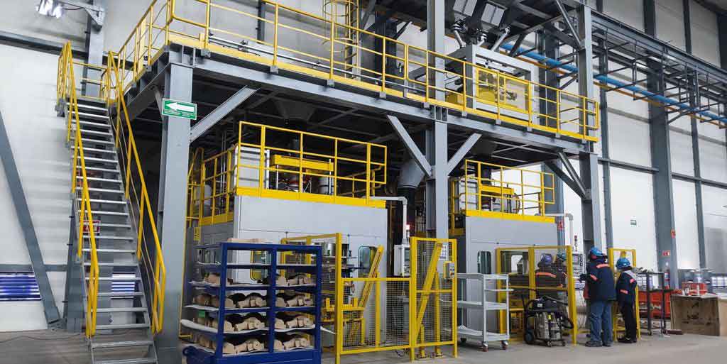
The manufacturing quality of the replacement steel castings is paramount. Modern casting techniques, such as computer-simulated solidification and advanced non-destructive evaluation (NDE), produce components with superior metallurgical consistency and fewer internal flaws compared to their historical counterparts. The material specification for these new bearings typically calls for a high-grade cast steel like ASTM A148, with stringent Charpy V-notch impact toughness requirements to withstand dynamic loading and low temperatures. The machining of the rocking surfaces and pin holes must be to exacting tolerances to ensure smooth rotation and proper load distribution, a significant improvement over older fabrication standards.
Risk management is woven into every step. A formal Hazard Analysis and Risk Assessment (HARA) is conducted, leading to a detailed method statement and contingency plans. Key risks and mitigations include:
| Risk | Mitigation Strategy |
|---|---|
| Structural damage from asynchronous jacking. | Use of a synchronized jacking system with real-time monitoring and manual override controls. Pre-lift rehearsal and operator training. |
| Over-stress in Continuous Welded Rail (CWR). | Mandatory stress relief (de-tensioning) of the rail in the affected zone prior to any lifting activity, based on recorded rail temperature. |
| Damage to signaling/communication cables attached to the bridge. | Early identification, agreement with infrastructure owners, physical protection or temporary re-routing during the work, with their staff in attendance. |
| Failure to complete critical path work within the blockade window. | Detailed time-based work plan with clear milestones. Use of pre-fabricated components (like the new steel castings). Having “hot” contingency plans (e.g., ability to temporarily support the bridge and reopen if bearing alignment takes too long). |
| Discovery of unforeseen deterioration in the supporting concrete pedestal. | Having materials and procedures on standby for rapid concrete repair and epoxy anchoring, with pre-approved mix designs and cure-accelerating measures. |
Beyond the immediate execution, this methodology offers profound insights for asset management. The condition assessment that triggers such a project relies on advanced inspection techniques, including photogrammetry to measure displacement and ultrasonic testing to probe the integrity of the massive steel castings. The data collected during the replacement—actual versus predicted jacking forces, measured displacements, grout performance—feeds back into predictive models for the remaining population of similar bearings on the network. It allows engineers to refine remaining life assessments and prioritize future interventions more effectively.
In conclusion, the replacement of deteriorated cast steel rocker bearings on a live railway is a pinnacle of precision civil engineering. It demands a synthesis of structural mechanics, railroad operations logistics, metallurgical knowledge of steel castings, and rigorous risk management. The synchronous hydraulic jacking method has proven to be a robust and reliable technique, enabling the safe exchange of these critical components within the severe temporal constraints of a mainline railway’s operating schedule. The project underscores a vital truth: the longevity and safety of our infrastructure often depend on our ability to meticulously renew its foundational elements, like these monumental steel castings, with minimal disruption to the vital services they support. The lessons learned and the protocols refined continue to inform best practices for the stewardship of aging railway infrastructure worldwide, ensuring that the bridges built with yesterday’s steel castings can reliably carry tomorrow’s trains.