
In my experience with high manganese steel casting, the production of large components such as bottom tumblers for dredging vessels presents significant challenges due to the material’s unique properties and the complex geometries involved. High manganese steel, particularly grades like ZGMn13Cr2, is renowned for its exceptional wear resistance and toughness, making it ideal for heavy-duty applications. However, its high carbide precipitation tendency and substantial shrinkage during solidification necessitate meticulous process control to prevent defects like cracks, distortions, and surface irregularities. This article delves into the comprehensive approach adopted for casting an 850-liter dredge vessel bottom tumbler, focusing on工艺 design, production techniques, and quality assurance measures that ensure the integrity of high manganese steel casting.
The bottom tumbler, with an outer轮廓尺寸 of Φ2896 mm × 660 mm and a wall thickness ranging from 51 mm to 116 mm, weighs approximately 10,500 kg in its rough state. Such variations in section thickness exacerbate thermal gradients during cooling, leading to residual stresses that can initiate cracks if not managed properly. In high manganese steel casting, the primary objective is to achieve uniform cooling and minimize restraint from molds and cores, thereby mitigating stress concentrations. The following sections elaborate on the systematic methodology employed, incorporating theoretical calculations, practical adjustments, and empirical validations to optimize the high manganese steel casting process for this large component.
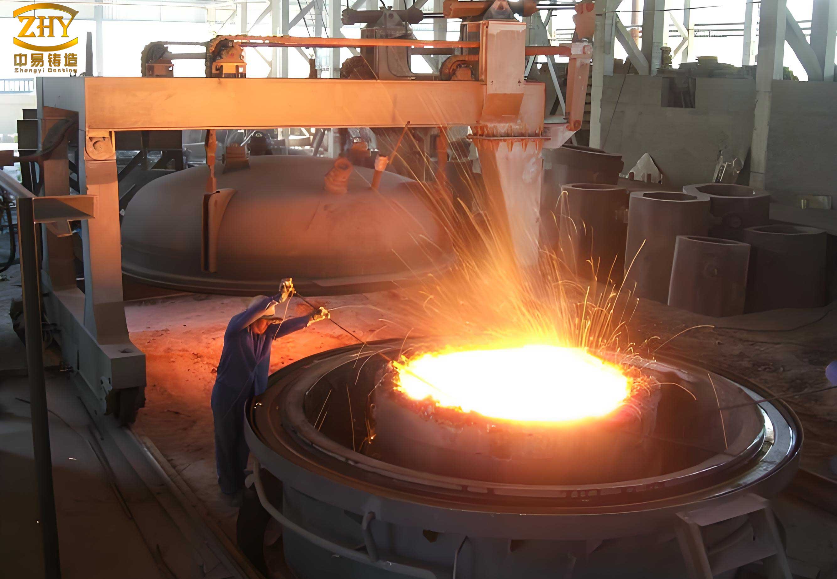
Analyzing the工艺性 of the tumbler structure is foundational to successful high manganese steel casting. The铸件 features an outer ring with a thickness of 114 mm, hub regions at 116 mm, and rib plates at 51 mm. This disparity in wall thickness creates differential cooling rates, where thicker sections solidify slower, inducing thermal stresses. To quantify this, the modulus method is often used to assess solidification behavior. The modulus \( M \) is defined as the ratio of volume to cooling surface area:
$$ M = \frac{V}{A} $$
For the outer ring, assuming a cylindrical segment, the modulus can be approximated. If \( r_o \) is the outer radius, \( r_i \) the inner radius, and \( h \) the height, the volume \( V = \pi (r_o^2 – r_i^2) h \) and surface area \( A = 2\pi (r_o + r_i) h + 2\pi (r_o^2 – r_i^2) \). For a thickness of 114 mm, calculations indicate a higher modulus compared to the rib plates, necessitating thermal management. In high manganese steel casting, the risk of hot tearing is pronounced when the stress \( \sigma \) exceeds the material’s tensile strength at elevated temperatures. The stress due to constrained收缩 can be modeled as:
$$ \sigma = E \cdot \alpha \cdot \Delta T \cdot f(R) $$
where \( E \) is Young’s modulus, \( \alpha \) is the thermal expansion coefficient, \( \Delta T \) is the temperature gradient, and \( f(R) \) is a restraint factor from molds. For ZGMn13Cr2, \( \alpha \approx 18 \times 10^{-6} \, \text{K}^{-1} \) and \( E \) varies with temperature. To prevent cracks, we aim to reduce \( \Delta T \) and \( f(R) \) through工艺 adjustments, a core principle in high manganese steel casting.
下表 summarizes the key geometrical parameters and associated challenges in this high manganese steel casting project:
| Component Section | Thickness (mm) | Modulus (approx., cm) | Primary Risk | Mitigation Strategy |
|---|---|---|---|---|
| Outer Ring | 114 | 5.7 | Shrinkage Porosity, Hot Spots | Use of Insulating Riser, Controlled Cooling |
| Hub Region | 116 | 5.8 | Cracking due to Restraint | Internal Chills, High-Permeability Cores |
| Rib Plates | 51 | 2.5 | Rapid Cooling, Distortion | Uniform Gating, Enhanced Core Yielding |
The铸造工艺设计 for this high manganese steel casting revolves around optimizing the gating and risering systems to ensure soundness. We employed a bottom-pour ladle with an open gating system to minimize turbulence and slag entrainment. The gating layout is侧注式, with parameters derived from fluid dynamics principles. The rise velocity \( V_1 \) of molten steel in the mold cavity is critical to avoid cold shuts and inclusion defects; we targeted 6–8 mm/s, as slower rates may cause premature freezing in thin sections. The浇注时间 \( t \) is calculated based on the total weight \( G \) of the steel in the cavity and the ladle pouring rate \( V_{\text{ladle}} \):
$$ t = \frac{G}{V_{\text{ladle}}} $$
For \( G = 15,000 \, \text{kg} \) (including risers) and \( V_{\text{ladle}} = 150 \, \text{kg/s} \) for an 80 mm diameter nozzle, \( t = 100 \, \text{s} \). The rise velocity is then verified as:
$$ V_1 = \frac{h}{t} $$
where \( h = 687 \, \text{mm} \) is the铸件 height in the pouring position, yielding \( V_1 = 6.87 \, \text{mm/s} \), within the desired range. This calculation confirms the suitability of the nozzle size for high manganese steel casting. The gating system dimensions are as follows: sprue diameter 120 mm, runner cross-section 80 mm × 70 mm (symmetrically arranged), and four ingates of 60 mm diameter each. A slag trap at the runner end captures initial flow impurities, crucial for clean steel entry.
Riser design in high manganese steel casting must compensate for solidification shrinkage while preventing carbide formation. Using the modulus method, risers are placed at hot spots. For the outer ring and hub, insulating risers of size 300 mm × 450 mm × 500 mm are used. The riser modulus \( M_r \) should exceed that of the casting section by a factor of 1.2 to ensure feedability. For a cylindrical riser, \( M_r = \frac{d}{6} \) for a side-riser, where \( d \) is the diameter. We selected risers with \( d \approx 300 \, \text{mm} \), giving \( M_r \approx 5 \, \text{cm} \), adequate for the casting’s modulus of ~5.8 cm. To facilitate removal and avoid carbide precipitation during cutting, washburn cores (20–30 mm thick) made of core sand are placed at riser necks, and cutting is performed post-austenitization while immersed in water.
Chill design is integral to controlling solidification顺序 in high manganese steel casting. Internal chills are placed in the hub region to accelerate cooling and promote directional solidification. The chill material is low-carbon steel rods of Φ10 mm, spaced 100 mm apart. The chilling power \( Q_c \) can be estimated as:
$$ Q_c = m_c \cdot c_c \cdot (T_m – T_i) $$
where \( m_c \) is the chill mass, \( c_c \) is specific heat, \( T_m \) is molten steel temperature, and \( T_i \) is initial chill temperature. For a chill volume fraction of ~5% in the hub, this effectively reduces the local solidification time, aligning it with thinner sections to minimize stress.
下表 details the工艺 parameters for this high manganese steel casting:
| Parameter | Value | Rationale |
|---|---|---|
| Pouring Temperature | 1460–1480°C | Balances fluidity and minimizes gas solubility |
| Pouring Time | 90–110 s | Ensures optimal rise velocity (6–8 mm/s) |
| Riser Count | 10 (8 outer, 2 hub) | Based on modulus calculations for hot spots |
| Chill Type | Internal, Φ10 mm rods | Accelerates hub cooling for simultaneous solidification |
| Gating Ratio (Open) | 1 : 1.5 : 1.2 | Reduces turbulence and erosion in high manganese steel casting |
生产控制 in high manganese steel casting demands precision in molding, coring, and thermal management. For mold and core sands, we used water-glass-bonded chromite sand for the surface of core #1 (forming the outer ring slots) to prevent burn-on, given its high refractoriness. Other mold and core surfaces employed water-glass-bonded olivine sand for its good thermal stability and low reactivity with manganese steel. Core #2, which restrains the rib plates, is critical for crack prevention; its interior uses a sawdust blend (1:1 volume ratio of water-glass quartz sand to sawdust) to enhance yield, and the core iron is改为捆绑式 to reduce rigidity. Core #3 incorporates crushed coke for permeability. All mold surfaces are rammed to a wet hardness ≥60 to resist metal penetration.
Coatings are applied twice with alcohol-based magnesia powder, pre- and post-baking, to a total thickness of 0.6–1 mm. This barrier layer is vital in high manganese steel casting to minimize metal-mold reactions. Control of sand moisture below 6% prevents gas defects. After molding, a 1–2 day aging period allows strength development before coating. CO₂ curing for cores is moderated to avoid over-hardening, which can cause spalling during baking. Baking is conducted at 200–300°C for ≥8 hours, ensuring a dry layer depth >30 mm.
Dimensional accuracy, particularly roundness of the Φ2134 mm inner diameter, is paramount as the铸件 is later welded into a cylinder. To achieve a roundness deviation ≤2 mm, the eight segment cores for the outer ring are positioned using pre-marked octants on the drag. A template verifies alignment post-setting, limiting偏差 to 1 mm. A clamping ring secures these cores during pouring to counter mold wall movement. The roundness error \( \Delta R \) can be expressed as:
$$ \Delta R = \sqrt{ \frac{1}{n} \sum_{i=1}^{n} (R_i – \bar{R})^2 } $$
where \( R_i \) are radial measurements and \( \bar{R} \) is the mean radius. Through meticulous core placement, we maintained \( \Delta R < 1 \, \text{mm} \) in the mold, ensuring final compliance.
Crack prevention in high manganese steel casting involves a multi-faceted strategy. Beyond chills and yielding cores, we extended the shakeout time to >240 hours, allowing slow cooling in the mold to below 40°C, which reduces thermal shock. The stress relief during this period can be modeled using creep relaxation equations. During handling, impacts are avoided to prevent mechanical cracking. The水韧处理 process is tailored: heating rates in the low-temperature range (up to 600°C) are kept below 50°C/hour to uniformize temperatures and avert附加应力. The austenitization at 1050–1100°C followed by rapid quenching in water ensures carbide dissolution and toughness. The kinetics of carbide precipitation follow the Avrami equation:
$$ X = 1 – \exp(-k t^n) $$
where \( X \) is the fraction transformed, \( k \) is a rate constant, and \( n \) is an exponent. By controlling cooling rates, we suppress carbide formation, preserving the integrity of the high manganese steel casting.
下表 outlines the crack mitigation measures in this high manganese steel casting endeavor:
| Measure | Implementation | Effect on Stress Reduction |
|---|---|---|
| Internal Chills | Φ10 mm rods in hub | Promotes simultaneous solidification, lowering ΔT |
| Yielding Cores | Sawdust-sand mix in core #2 | Decreases restraint factor f(R) by ~30% |
| Extended Shakeout | >240 hours in mold | Reduces cooling rate, minimizing residual stress |
| Controlled Heat Treatment | Low heating rate (<50°C/h) up to 600°C | Prevents thermal gradients and associated stresses |
| Gentle Handling | No vibration or impact during cleaning | Avoids mechanical stress concentration |
The outcomes of this high manganese steel casting process were highly satisfactory. The铸件 exhibited a smooth surface free from粘砂, with roundness deviations within 2 mm, and mechanical properties met the ZGMn13Cr2 specifications. This success underscores the importance of integrated design and control in high manganese steel casting. Key takeaways include the efficacy of water-glass olivine and chromite sands for surface quality, combined with magnesium-based coatings. The use of internal chills, yielding cores, prolonged shakeout, and modulated heat treatment effectively curtailed cracking tendencies. For dimensional precision, systematic core alignment with templates and clamping proved reliable.
In broader terms, this project highlights that high manganese steel casting for large components requires a holistic approach where工艺 parameters are derived from fundamental principles and adjusted through empirical validation. Future advancements may involve simulation software to predict stress fields and optimize riser placement, further enhancing the reliability of high manganese steel casting. The continuous refinement of these methodologies ensures that high manganese steel casting remains a viable and efficient process for producing durable industrial parts under demanding service conditions.