
The production of high-performance machine tool components represents a critical challenge in advanced manufacturing. Among various materials, gray cast iron with a high carbon equivalent (CE) has garnered significant attention for manufacturing large, complex, and high-stress casting parts, such as bed frames, columns, and tables. These casting parts are fundamental to the precision, stability, and longevity of machining centers. The inherent advantages of high CE gray iron—excellent castability, good damping capacity, and favorable mechanical properties—make it ideal. However, achieving these properties consistently in heavy-section casting parts without defects like shrinkage porosity, cracking, or undesirable graphite structures requires meticulous process control. This article, from a first-person research and application perspective, delves into the development and optimization of a short-flow production process for such casting parts, focusing on enhancing quality, reducing cost and cycle time, and ensuring superior metallurgical integrity.
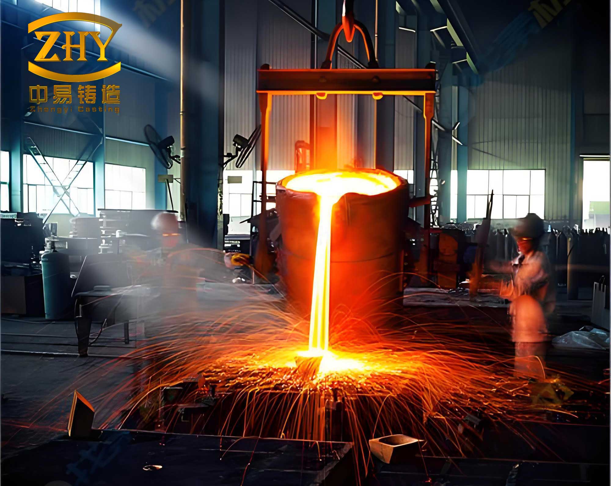
The trend towards shorter, more integrated production routes is key to improving competitiveness. The traditional long route involving multiple remelting stages is inefficient. Our developed short-flow process innovatively combines blast furnace hot metal pretreatment with intermediate frequency induction furnace fine-tuning. This approach significantly reduces energy consumption and metal loss while providing greater flexibility in final chemistry adjustment. The target casting part for this study was the bed for a HMC8800 horizontal machining center, a massive component weighing approximately 12,270 kg with dimensions of 4,900 mm × 2,900 mm × 1,490 mm and an average wall thickness of 30 mm. Producing this large, high-integrity casting part to a specification of HT300 (minimum tensile strength of 300 MPa) served as the perfect testbed for our optimized high CE gray iron process.
Characteristics and Metallurgical Principles of High CE Gray Iron for Casting Parts
High carbon equivalent gray iron, typically with a CE greater than 3.85%, exhibits unique characteristics crucial for heavy-duty machine tool casting parts. The high carbon content, primarily through its influence on graphite formation, provides excellent fluidity, reducing misrun and cold shut defects in complex thin sections of a large casting part. Furthermore, the expansion associated with graphite precipitation during solidification helps compensate for shrinkage, minimizing internal porosity. However, the very properties that benefit castability can detract from mechanical strength if not properly controlled. A high CE generally promotes the formation of larger, coarser graphite flakes and a ferritic matrix, which lowers strength and hardness. Therefore, the core challenge in producing a high-performance casting part is to maintain a high CE for castability and low stress while simultaneously achieving a fully pearlitic matrix with fine, uniformly distributed type A graphite for strength. This is governed by key metallurgical factors:
- Carbon Equivalent (CE) and Silicon-Carbon Ratio (Si/C): The CE is calculated using the formula: $$CE = \%C + \frac{1}{3}(\%Si + \%P)$$. While a high CE (3.8-3.9%) is targeted for low stress and good castability, the ratio of silicon to carbon becomes critically important. A higher Si/C ratio (>0.75) enhances graphitization potential and increases ferrite stability. Our strategy was to employ this high Si/C ratio but counteract the ferritizing effect through targeted alloying.
- Inoculation: This is a non-equilibrium treatment essential for refining graphite morphology. Effective inoculation increases the number of graphite nucleation sites, promoting the formation of fine, interdendritic type A graphite instead of undercooled types (D, E). This refinement significantly improves tensile strength and thermal conductivity of the final casting part.
- Alloying and Pearlite Stabilization: To ensure a pearlitic matrix despite a high Si/C ratio, minor additions of pearlite-stabilizing elements are crucial. We employed a synergistic combination of Nitrogen (N) and Tin (Sn), along with Chromium (Cr). Nitrogen, in solution, strongly promotes pearlite formation and refines graphite. Tin is an extremely potent pearlite stabilizer with minimal risk of creating hard spots. Chromium adds moderate pearlite stability and slight carbide formation for wear resistance.
- Cooling Rate Control: For a large casting part with varying sections, controlling the cooling rate through mold design and sand properties is vital to prevent thermal stresses, cracking, and to ensure uniform microstructure development.
The Short-Flow Production Process for High-Performance Casting Parts
The entire manufacturing sequence for the bed casting part was optimized under the short-flow philosophy. The process chain is: Material Selection & Charge Calculation → Blast Furnace Hot Metal Pretreatment → Induction Furnace Melting & Adjustment → Molding with 3D Printed Cores → Pouring → Cooling & Shakeout → Heat Treatment (Stress Relief) → Finishing & Inspection.
1. Material Selection and Charge Design
The foundation of a quality casting part is pure and consistent charge materials. Our charge composition was designed to leverage the cost and efficiency of the short flow.
| Material | Percentage (%) | Key Requirements |
|---|---|---|
| Blast Furnace Hot Metal (Pretreated) | 45 | Desulfurized and dephosphorized; temperature raised to 1650-1720°C in pretreatment ladle. |
| Selected Steel Scrap | 30 | Low alloy, clean, with consistent chemistry to dilute impurities. |
| Internal Returns (Gates, Risers) | 20 | Clean, known chemistry; addition limited to ensure melt freshness. |
| Alloying Additives (FeSi, FeMn, Cr, etc.) | 5 | High-purity materials for precise chemistry adjustment. |
2. Melting and Chemical Composition Control
The pretreated hot metal is transferred to a medium-frequency coreless induction furnace. This furnace provides excellent stirring action for homogeneity and precise temperature control. The melting and treatment protocol is as follows:
- Superheating: The metal is superheated to 1480-1550°C to ensure complete dissolution of nuclei and additives.
- Pre-inoculation/Carbide Inoculation: To increase nucleation sites, 0.1% fine granular silicon carbide (SiC, 0.2-1 mm) is sprinkled on the melt surface. SiC dissolves and provides heterogeneous sites for graphite precipitation.
- Final Chemistry Adjustment: Alloys are added to hit the target range. The core chemical strategy for the casting part is:
- High CE: 3.80-3.85%
- High Si/C: > 0.75
- Micro-alloying: Mn: 0.8-1.0%, Cr: 0.1-0.2%
- Pearlite Stabilization: Sn: 0.04-0.06%, N: 90-110 ppm (added via nitrogen-bearing manganese alloy).
- Inoculation: A two-stage inoculation is performed. First, 0.4% FeSi-Ba-Ca inoculant is added during tapping (ladle inoculation). Second, a late stream inoculation using 0.1% fine 75% Ferrosilicon (0.2-0.7 mm) is performed during pouring to ensure potency.
- Temperature Control: The pouring temperature for this large casting part is carefully maintained between 1380-1410°C to balance fluidity and minimization of shrinkage defects.
| Stage | CE | C | Si | Mn | P | S | Sn | Cr | N (ppm) |
|---|---|---|---|---|---|---|---|---|---|
| Base Iron (After Scrap Melting) | 3.41 | 3.04 | 1.07 | 0.51 | 0.023 | 0.029 | 0.0076 | 0.094 | 33 |
| Final Inoculated Iron (Target) | 3.84 | 3.02 | 2.44 | 0.86 | <0.04 | 0.04-0.08 | 0.047 | 0.15 | 119 |
3. Molding and Core Making Process
Producing the intricate internal cavities and external geometry of the bed casting part required advanced molding. We employed a furan no-bake resin sand process, enhanced with 3D printing technology for complex cores.
- 3D Printed Sand Cores: Critical internal passages and complex features were manufactured as precise sand cores using binder jetting 3D printing. This eliminated the need for complex core boxes, reduced lead time, and ensured excellent dimensional accuracy and surface finish for the casting part.
- Coating Application: A refractory coating with a controlled viscosity of 38°Bé was uniformly applied to all mold and core surfaces. This is essential to prevent metal penetration (burn-on) and improve the surface finish of the final casting part.
- Process Control in Resin Sand: Key parameters were strictly monitored to ensure mold strength and stability for the massive pouring.
| Parameter | Target Range | Significance for the Casting Part |
|---|---|---|
| Resin Addition | 1.0 – 1.1% | Provides bonding strength. |
| Catalyst Addition (Toluene Sulfonic Acid) | 30 – 50% of resin | Controls curing speed and final strength. |
| Compressive Strength | 0.8 – 1.2 MPa | Ensures mold can withstand metallostatic pressure without deformation. |
| Tensile Strength | 0.4 – 0.5 MPa | Indicates core handling strength and resistance to cracking. |
| Surface Hardness | 70 – 90 (Scale reading) | Ensures mold surface stability during handling and pouring. |
| Permeability | 120 – 200 | Allows gases from mold and metal to escape, preventing blows in the casting part. |
4. Gating System Design and Pouring Practice
A properly designed gating system is paramount for a defect-free casting part. For the bed casting, a pressurized system was chosen to ensure rapid and turbulent-free filling.
- System Design: The ratio of choke area to total runner area to total ingate area was designed as: $$\Sigma S_{choke} : \Sigma S_{runner} : \Sigma S_{ingate} = 1.2 : 1 : 0.9$$. This promotes a smooth, non-aspirating flow of metal into the mold cavity.
- Pouring Parameters: The total pouring weight of ~12.5 tons (including gating) required a controlled pour time of 60-90 seconds. This was achieved by calculating the required choke cross-sectional area based on the defined pouring time and metallostatic head.
Evaluation of the Produced Casting Part: Mechanical Properties and Metallurgical Quality
The success of the process is ultimately judged by the properties of the finished casting part. Extensive testing was conducted both on separately cast test bars (from the same heat) and on the actual bed casting.
1. Residual Stress and Hardness
Minimizing residual stress is critical for the long-term dimensional stability of a machine tool casting part. Hardness uniformity indicates consistent microstructure. Measurements were taken at multiple locations on the stress-relief annealed bed.
| Point | Principal Stress σ₁ (MPa) | Principal Stress σ₂ (MPa) |
|---|---|---|
| 1 | -29.3 | -69.2 |
| 2 | -22.8 | -89.6 |
| 3 | 20.5 | -13.9 |
| … | … | … |
| 12 | 20.9 | 9.7 |
The stresses are relatively low and predominantly compressive, which is favorable. Hardness was measured at 12 locations using a portable Brinell hardness tester.
| Point | 1 | 2 | 3 | 4 | 5 | 6 | 7 | 8 | 9 | 10 | 11 | 12 | Avg. |
|---|---|---|---|---|---|---|---|---|---|---|---|---|---|
| HBW | 209 | 214 | 207 | 216 | 203 | 215 | 202 | 202 | 201 | 206 | 209 | 208 | 207 |
The uniformity of hardness (201-216 HBW) across this large casting part demonstrates excellent process control and consistent cooling.
2. Metallurgical Quality Indices
Beyond standard mechanical tests, several derived indices provide a deeper understanding of the metallurgical quality achieved for this casting part.
- Eutectic Saturation (Sc): Indicates the relative position of the composition to the eutectic point. A higher Sc generally means better castability and lower stress.
$$Sc = \frac{\%C_{actual}}{\%C_{eutectic}} = \frac{3.02}{4.26 – \frac{2.44+0.026}{3}} \approx \frac{3.02}{3.43} \approx 0.88$$ - Relative Strength (RG) / Maturity Degree: Compares the actual strength to the normal strength expected for that Sc. An RG > 1.0 indicates a high-quality melt with effective inoculation.
$$RG = \frac{R_{m(measured)}}{1000 – 800 \times Sc}$$
For our test bar with $R_m = 310.9$ MPa and $Sc = 0.88$:
$$RG = \frac{310.9}{1000 – 800 \times 0.88} = \frac{310.9}{296} \approx 1.05$$ - Relative Hardness (RH) / Hardening Degree: Compares the actual hardness to the normal hardness. An RH < 1.0 is desirable, indicating lower hardness for a given strength, which improves machinability.
$$RH = \frac{HBW_{measured}}{530 – 344 \times Sc}$$
$$RH = \frac{207}{530 – 344 \times 0.88} = \frac{207}{530 – 302.7} = \frac{207}{227.3} \approx 0.91$$ - Quality Coefficient (Qi): The ratio of RG to RH. A Qi > 1.0 indicates a superior combination of high strength and low hardness.
$$Qi = \frac{RG}{RH} = \frac{1.05}{0.91} \approx 1.19$$ - Machinability Index (m): A direct indicator of ease of machining for the casting part. Higher values are better.
$$m = \frac{R_m (MPa)}{HBW} = \frac{310.9}{207} \approx 1.50$$
| Index | Symbol | Calculated Value | Interpretation |
|---|---|---|---|
| Eutectic Saturation | Sc | 0.88 | High castability, low inherent stress. |
| Relative Strength (Maturity) | RG | 1.05 | Strength exceeds normal expectation for this CE. |
| Relative Hardness | RH | 0.91 | Hardness is lower than normal, good for machining. |
| Quality Coefficient | Qi | 1.19 | Excellent overall metallurgical quality. |
| Machinability Index | m | 1.50 | Excellent machinability, comparable to premium grades. |
3. Microstructural Analysis
Microstructural evaluation of the test bar confirmed the effectiveness of the process. The graphite structure was predominantly Type A (>96%), with a size rating of 4 (fine to medium flake). The matrix was over 98% pearlite, with no significant ferrite halos around the graphite, confirming the success of the N+Sn+Cr pearlite stabilization strategy despite the high Si/C ratio of 0.81. This microstructure directly explains the achieved tensile strength of 310.9 MPa and the high elastic modulus of 124 GPa, both critical for a rigid machine tool casting part.
Conclusion and Outlook
The integrated short-flow production process, combining blast furnace hot metal, precise induction furnace alloying, advanced molding, and rigorous metallurgical control, has proven highly successful for manufacturing high-carbon equivalent gray iron machine tool casting parts. The key achievement lies in decoupling the properties: maintaining a high CE (3.84%) and high Si/C ratio (0.81) for superb castability and low stress, while using synergistic micro-alloying (N, Sn, Cr) and potent inoculation to secure a fully pearlitic matrix with fine, type A graphite. This results in a casting part with excellent and uniform mechanical properties (Rm ~310 MPa, HBW ~207), outstanding metallurgical quality indices (Qi=1.19), and superior machinability (m=1.5).
This approach provides a robust framework for producing other high-performance, complex casting parts. Future work will focus on further refining the alloying system for even higher strengths (HT350 and above) at maintained or improved machinability, integrating real-time process monitoring and data analytics for predictive quality control, and exploring the use of other advanced binder systems for sand molds and cores to enhance the surface quality and dimensional precision of the final casting part. The pursuit of such optimized processes ensures that gray iron remains a competitive and high-performance material choice for critical components in advanced manufacturing.