
In my experience working on the localization of critical components for industrial machinery, the trial production of a brake disk presented a significant challenge due to its complex geometry and stringent material requirements. This brake disk, with an outer diameter of 1040 mm, a thickness of 52.5 mm, and numerous cooling fins 29.5 mm high, required high surface quality, minimal deformation, and internal soundness. After thorough analysis, my team and I decided to employ the sand coated iron mold casting process, which is renowned for its ability to produce dense, high-quality castings with minimal defects. Throughout this project, the sand coated iron mold casting technique was pivotal, and I will detail how we optimized it through composition control, pre-furnace processes, and mold modifications to achieve a successful trial.
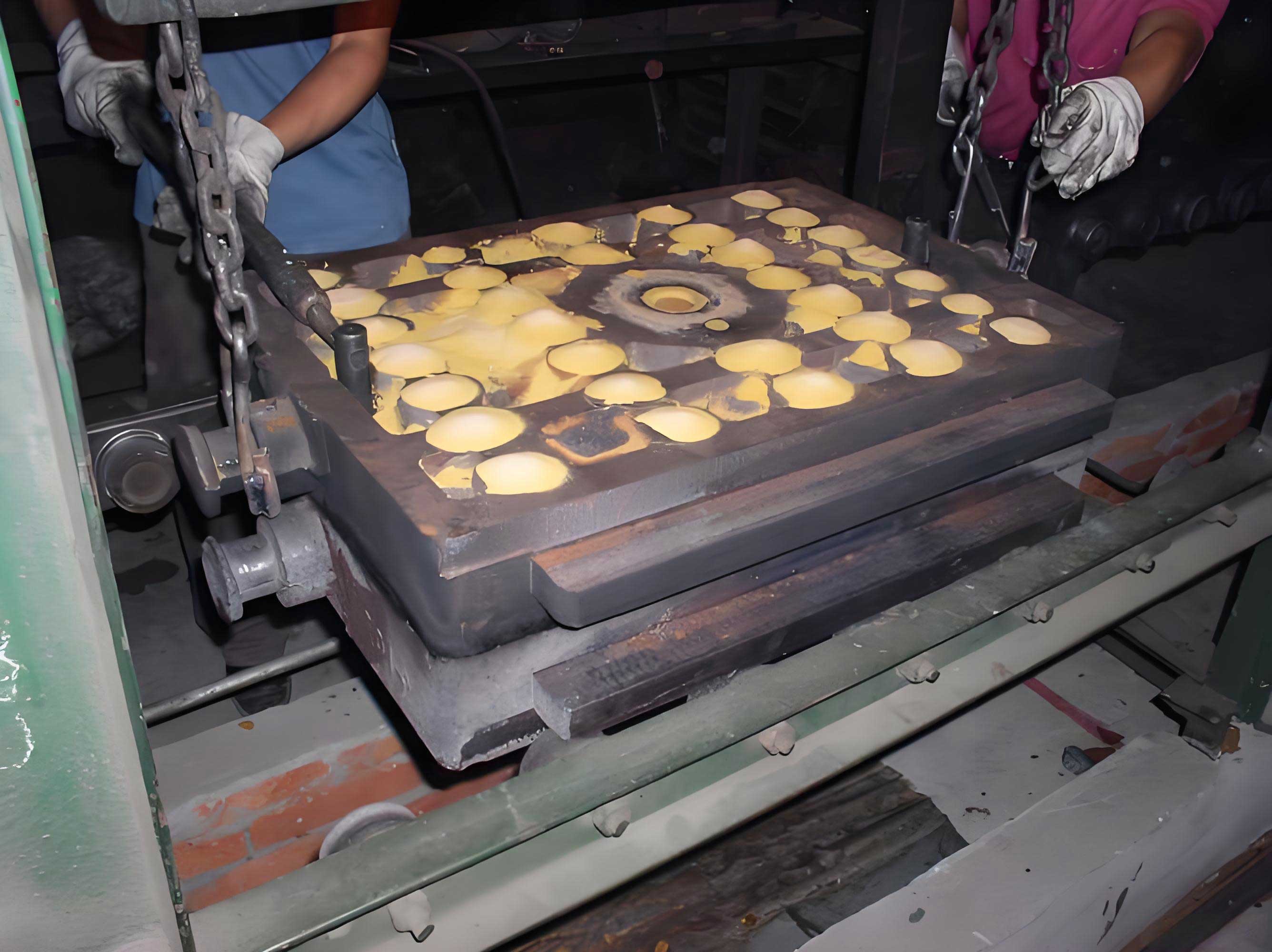
The sand coated iron mold casting process involves creating a sand mold by coating an iron mold with resin-bonded sand, which is then cured to form a precise cavity. This method offers rapid mold formation, enhanced cooling rates, and reduced casting defects such as shrinkage and porosity. For this brake disk, we designed the mold with a central sprue connected to two annular gates, incorporating two feeders for compensation and ceramic filters to prevent impurities. The use of sand coated iron mold casting allowed us to control solidification effectively, but initial trials revealed issues like shrinkage in thicker sections, prompting further refinements.
To meet the material specifications—tensile strength ≥400 MPa, yield strength ≥300 MPa, elongation ≥1.5%, Brinell hardness 190–250 HB, vermicular graphite rate ≥65%, and pearlite ≥50%—we focused on precise composition control. The alloy elements were carefully balanced to achieve a vermicular graphite iron (RuT 400) structure, avoiding excessive nodularization or gray iron tendencies. In sand coated iron mold casting, composition stability is crucial due to the rapid cooling, so we established strict ranges for each element, as summarized in the table below.
| Element | Control Range (wt.%) | Role in Sand Coated Iron Mold Casting |
|---|---|---|
| C | 3.5–3.9 | Enhances strength but reduces ductility; critical for graphite formation. |
| Si | 2.0–2.5 | Promotes graphiteization and self-compensation; reduces oxygen and nitrogen. |
| Mn | 0.7–1.3 | Stabilizes pearlite; improves hardness without affecting graphite morphology. |
| P | ≤0.03 | Harmful element; kept low to prevent brittleness. |
| S | ≤0.025 | Anti-vermicular element; consumes vermicularizing agents; minimized. |
| Cu | 0.7–1.2 | Alloying element; increases pearlite content and strength. |
| Mo | 0.2–0.4 | Refines pearlite; enhances high-temperature properties. |
| Ti | 0.1–0.2 | Alloying element; aids in grain refinement and graphite control. |
| Mg | 0.01–0.03 | From vermicularizing agent; modifies graphite shape and acts as an inoculant. |
| RE | 0.02–0.055 | From vermicularizing agent; purifies melt and improves casting properties. |
The interaction of these elements in sand coated iron mold casting can be modeled using empirical formulas to predict graphite morphology. For instance, the vermicular graphite rate (VGR) is influenced by the effective magnesium content, which we calculated based on sulfur levels. A simplified relation used in our trials is: $$VGR = k_1 \cdot (Mg_{eff}) – k_2 \cdot (S)$$ where \(Mg_{eff}\) is the effective magnesium after reaction, and \(k_1\) and \(k_2\) are constants derived from experimental data in sand coated iron mold casting. This helped us adjust the vermicularizing agent addition to achieve ≥65% VGR.
Pre-furnace process control was another critical aspect in sand coated iron mold casting. We meticulously managed melting, treatment temperatures, and timing to ensure consistent quality. The steps included charging alloys in a specific order, overheating to refine the melt, and performing vermicularization treatment. For sand coated iron mold casting, rapid cooling necessitates precise temperature control to avoid premature solidification in thin sections. Our thermal management strategy involved calculating the solidification time \(t_s\) using Chvorinov’s rule adapted for sand coated iron mold casting: $$t_s = C \cdot \left( \frac{V}{A} \right)^n$$ where \(V\) is volume, \(A\) surface area, \(C\) a mold constant specific to sand coated iron mold casting, and \(n\) an exponent around 2. By adjusting the mold design, we aimed to balance \(t_s\) across the disk to prevent shrinkage.
During melting, we heated the charge to 1510–1530°C for 8–10 minutes, then tapped at 1480°C. The vermicularizing agent and inoculant were placed in the ladle, and treatment occurred for 60–80 seconds. After stirring and slag removal, we sampled for spectral analysis and poured within 18 minutes to avoid vermicular graphite decay. The pouring temperature was maintained at 1420°C, with a fast pour to fill the sand coated iron mold casting cavity quickly. This timing is crucial in sand coated iron mold casting because the iron mold accelerates cooling, so delays can lead to incomplete filling or defects.
Initial trials with sand coated iron mold casting revealed shrinkage in thick sections due to uneven temperature distribution. To address this, we modified the mold by adding four feeding risers near the gates and incorporating internal chills in heavy areas. This improved the temperature equilibrium, a key principle in sand coated iron mold casting to ensure uniform solidification. The temperature gradient \(\nabla T\) across the disk was estimated using: $$\nabla T = \frac{T_{pour} – T_{solidus}}{d}$$ where \(d\) is the distance from the feeder, and we optimized riser placement to minimize \(\nabla T\) in sand coated iron mold casting.
After these adjustments, we conducted multiple trials and evaluated the results. The mechanical properties and microstructural data are summarized below, demonstrating that our sand coated iron mold casting approach met all specifications.
| Trial | Tensile Strength (MPa) | Elongation (%) | Brinell Hardness (HB) | Vermicular Graphite Rate (%) | Pearlite Content (%) |
|---|---|---|---|---|---|
| 1 | 413 | 3.5 | 180 | ≈75 | ≈40 |
| 2 | 527 | 1.7 | 225 | ≈70 | ≈80 |
| 3 | 550 | 3.3 | 240 | ≈80 | ≈80 |
| 4 | 494 | 3.4 | 210 | ≈75 | ≈85 |
These results exceed the national standards for RuT 400, highlighting the effectiveness of sand coated iron mold casting. Non-destructive testing confirmed the absence of internal defects like shrinkage or gas holes, validating our process optimizations. The success of this trial underscores the potential of sand coated iron mold casting for high-performance components, as it combines the benefits of rapid cooling with precise mold integrity.
In conclusion, through diligent application of sand coated iron mold casting, coupled with rigorous composition and process controls, we successfully localized the brake disk production. The key lessons include the importance of temperature field balancing in sand coated iron mold casting to eliminate shrinkage, and the need for precise alloy management to achieve desired graphite structures. This project not only delivered a component with performance matching imported parts but also established a foundation for further domestications using sand coated iron mold casting. Future work could explore automating the sand coated iron mold casting process or optimizing riser designs through simulation software to enhance efficiency.