
In my extensive experience within the foundry industry, the production of high-quality machine tool castings represents a complex interplay of precise engineering and meticulous process management. The stability, durability, and precision of these castings are foundational to the entire mechanical manufacturing sector, often serving as a benchmark for a nation’s metallurgical and casting capabilities. The journey from raw materials to a finished machine tool casting is a chain of interdependent stages—molding and core-making, melting and pouring, and post-processing—where the slightest fluctuation in any parameter can compromise the final product’s integrity. I will delve deeply into a holistic control methodology, blending macro-level quality systems with granular technical keypoints, to ensure excellence in machine tool castings.
The cornerstone of consistent quality for machine tool castings lies in implementing a robust, plant-wide Quality Assurance (QA) system. From my perspective, this transcends mere inspection; it is about weaving quality into the very fabric of every operation. A successful system mandates comprehensive quality management activities, strengthened foundational work, and precise process control. The core philosophy is to link individual responsibilities across all production stages into a seamless, standardized, and efficient workflow, ensuring every action is procedural and traceable.
Process control, or工序控制, is the most critical factor influencing the quality of machine tool castings. The first step I always advocate is mapping the entire process flow and establishing definitive Control Points (CPs). These are stages where process data is monitored as key quality parameters. The selection criteria for CPs are straightforward: identify steps prone to defects or those with a significant impact on the final casting’s properties. For each CP, we must define the control content, reference standards, control methods, and measurement tools. Documentation is vital—utilizing report sheets, checklists, and records to facilitate self-inspection, mutual inspection, and dedicated inspection. The goal is proactive prevention, preparing in advance to secure the quality of the machine tool castings. Below is a simplified table outlining potential control points in a typical foundry flow for machine tool castings.
| Process Stage | Control Point | Key Parameter(s) | Control Standard | Monitoring Method |
|---|---|---|---|---|
| Molding & Core-making | Sand Preparation | Green Strength, Moisture Content, Clay Content | ASTM AFS Standards | Laboratory Testing (e.g., Universal Sand Strength Tester) |
| Molding & Core-making | Pattern/Model Inspection | Dimensional Accuracy, Draft Angle, Surface Finish | Engineering Drawing Specifications | Coordinate Measuring Machine (CMM) / Visual Gauge |
| Melting | Furnace Charge & Composition | Charge Material Ratios (Pig Iron, Scrap Steel, Returns) | Internal Metallurgical Specification | Weight Scale Logs, Spectroscopic Analysis |
| Melting | Molten Metal Analysis | Carbon Equivalent (CE), Silicon/Carbon Ratio, Alloy Content | Target Chemistry Ranges | Optical Emission Spectrometer |
| Pouring | Pouring Temperature & Speed | Temperature (°C), Pouring Time (seconds) | Defined per Casting Section Thickness | Immersion Thermocouple, Timed Pour Tests |
| Post-Processing | Shakeout & Cleaning | Cooling Time, Media Size & Flow in Shot Blast | Internal Work Instructions | Time Control, Visual & Surface Roughness Check |
Equally crucial is the human factor. I firmly believe in thorough process briefing and training for the foundry personnel. Workers must understand the ‘why’ behind each specification, not just the ‘what’. This fosters a sense of ownership and encourages voluntary adherence to procedures, while also tapping into their practical creativity for continuous improvement. Management’s role is to audit and validate at the molding stage, acting as the final gatekeeper of process discipline before metal is poured.
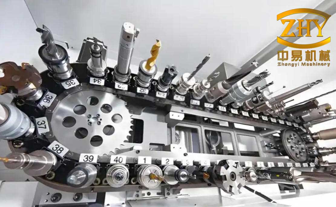
The molding and core-making phase sets the geometric and surface destiny of the machine tool casting. Every detail here influences dimensional stability, surface finish, and defect formation. The primary technical considerations are the selection of the molding method, the quality of the molding sand, and the rigorous control of the shell-making process (in investment casting) or mold hardening.
For machine tool castings, common molding methods include solid pattern flask molding, split pattern flask molding, sweep molding, false cope molding, skeleton molding, pit molding, and three-part flask molding. Each has its merits and limitations. The choice must prioritize the quality requirements of the casting—such as complexity, dimensional tolerance, and production volume—before considering process simplicity and cost. The table below compares some prevalent methods for producing machine tool castings.
| Molding Method | Typical Application in Machine Tool Castings | Advantages | Disadvantages |
|---|---|---|---|
| Green Sand Flasking (Split Pattern) | Beds, housings, medium-complexity components | Low cost, high productivity, good dimensional accuracy | Limited for very complex geometries, surface finish can be variable |
| Chemical Bonded Sand (e.g., Resin Sand) | Large, heavy-sectioned beds, columns | High dimensional stability, good for low/medium volumes, complex shapes | Higher material cost, slower production cycle |
| Lost Foam Casting | Complex internal passageways (e.g., coolant channels) | Excellent design freedom, minimal parting lines, reduced machining | Pattern cost, potential for carbon defects, process control critical | Investment Casting (for precision parts) | Small, intricate tooling components | Exceptional surface finish and dimensional precision | Very high cost, size limitations, long process cycle |
Defects like sand inclusion, veining, or rough surface finish often originate from poor sand quality or uncontrolled shell-making. For green sand, key properties like moisture, green compressive strength, and permeability must be tightly controlled. In shell molding or investment processes for precision machine tool castings, the control of the primary coat is paramount. Inadequate control here is a primary cause of surface and sub-surface defects. I insist on stabilizing the drying humidity for the primary coat within a strict range, say 45-55%, and ensuring uniform ambient temperature and humidity. The slurry’s viscosity and pH must be monitored and maintained within specification to guarantee consistent coating composition and performance. A critical step in investment casting is thorough dewaxing to minimize residual wax within the shell, which can cause defects upon burnout.
The heart of metallurgical quality for machine tool castings—which are predominantly gray iron—lies in the melting and pouring operations. The industry trend is towards high carbon equivalent (CE) and high strength. Enhancing the metallurgical quality requires mastering several key nodes in these stages.
In melting, carbon equivalent control is paramount. A high CE is the pathway to achieving low casting stress, good machinability, and castability alongside high strength. The carbon equivalent for gray iron is commonly calculated using the formula:
$$CE = C + \frac{Si + P}{3}$$
where C, Si, and P are the weight percentages of carbon, silicon, and phosphorus, respectively. Historically, machine tool castings from some regions have operated at a lower CE compared to international benchmarks. A strategic, controlled increase in CE can be beneficial. Concurrently, the silicon-to-carbon ratio (Si/C) plays a vital role. A higher Si/C ratio helps prevent chill (white iron) in thin sections, promotes uniformity, enhances strength and hardness, and reduces residual stress. However, at high CE, a high Si/C can promote excessive ferrite formation, detrimental to overall performance. Therefore, an optimal Si/C ratio for high-quality machine tool castings is typically targeted around:
$$\frac{Si}{C} \approx 0.5 \text{ to } 0.7$$
Alloying is an indispensable supplement. Low alloying additions (e.g., Cr, Mo, Cu, Sn) serve to pearlite stabilization, strengthen ferrite, refine graphite and eutectic cells, and improve section sensitivity. At high carbon equivalent, these elements are crucial to maintain strength and hardness while mitigating interface sensitivity. The effect of common alloying elements on the properties of machine tool castings can be summarized as follows, where the strengthening factor $k$ for an element $i$ at concentration $w_i$ can be part of an empirical hardness model: $$H_{expected} = H_{base} + \sum (k_i \cdot w_i)$$
| Element | Primary Effect | Typical Addition Range (%) | Impact on Machine Tool Castings |
|---|---|---|---|
| Chromium (Cr) | Carbide Stabilizer, Pearlite Promoter | 0.1 – 0.5 | Increases hardness, wear resistance, strength; reduces graphitization. |
| Molybdenum (Mo) | Refines Pearlite, Increases Hardenability | 0.2 – 0.6 | Enhances tensile strength, thermal fatigue resistance, good for heavy sections. |
| Copper (Cu) | Pearlite Refiner, Mild Graphitizer | 0.5 – 1.2 | Improves strength, hardness, corrosion resistance, and pressure tightness. |
| Tin (Sn) | Powerful Pearlite Stabilizer | 0.05 – 0.1 | Ensures fully pearlitic matrix, increases hardness consistently. |
Charge makeup is also critical. The proportion of pig iron is generally kept below 30%, while the scrap steel ratio is judiciously increased to refine the microstructure. The molten iron temperature must be controlled within 1450°C to 1550°C to ensure proper fluidity and inoculation response.
Pouring is the culmination of melting preparation. The chemical composition, now fixed, interacts with the pouring parameters. While a higher CE increases graphite expansion during solidification and can reduce shrinkage porosity, an excessively high CE without adequate inoculation leads to coarse graphite and degraded mechanical properties—a balance vital for machine tool castings. Inclusions like slag or sand eroded from the ladle or gating system are catastrophic. They form when slag removal is incomplete, holding time post-treatment is insufficient, or the gating system design is poor. The prevention strategy involves meticulous cleaning of pouring systems, optimizing slag coagulant use, and improving the formulation of mold fluxes. The gating system design itself can be optimized using hydraulic principles, where the choke area $A_c$ is calculated to ensure a desired pouring time $t$ for a casting weight $W$ and assumed efficiency factor $\mu$ and head height $h$: $$A_c = \frac{W}{\rho \cdot \mu \cdot t \cdot \sqrt{2 g h}}$$ where $\rho$ is metal density and $g$ is gravity.
It is a common misconception that the quality of machine tool castings is sealed once they leave the mold. On the contrary, the post-processing stage—comprising cooling, shakeout, knockout, gate removal, shot blasting, fettling, rust prevention, and packaging—is where final dimensions, stress state, surface roughness, and form are locked in. Neglect here can nullify all prior excellent work, drastically reducing the yield of acceptable machine tool castings. This phase is often the most overlooked in quality control protocols.
Key nodes for rigorous control in post-processing of machine tool castings include shakeout, fettling, and rust prevention. Shakeout must occur only after the casting has cooled below a critical temperature to prevent warping or cracking due to residual stresses. For complex machine tool castings, this can be modeled using cooling curves and the concept of the eutectoid transformation temperature. Fettling (grinding, cutting) must be done precisely to avoid damaging the casting surface or altering critical dimensions. A systematic inspection regime is non-negotiable. Beyond dimensional checks, metallographic examination of the microstructure is essential to verify graphite morphology (Type A, size 4-6 is often desirable), pearlite content, and absence of carbides. Furthermore, advanced tests like dynamic elastic modulus measurement, residual stress analysis (e.g., using hole-drilling strain gauge method), and distortion checks under simulated load are increasingly important for premium machine tool castings. The relationship between microstructure and dynamic stiffness (closely related to damping capacity) can be complex, but a finer, well-distributed graphite structure generally improves this key property for machine tool castings.
In conclusion, achieving superior quality in machine tool castings is not a matter of chance but the result of a meticulously controlled, technology-driven process seamlessly integrated with principled quality management. From the macro-level architecture of a plant-wide quality assurance system down to the micro-level precision of carbon equivalent calculation and shell coat drying, every element is a link in an unbreakable chain. The foundry producing world-class machine tool castings must be a learning organization, constantly refining its control points, embracing data-driven decision-making, and empowering its workforce. By harmonizing advanced technical know-how—expressed through precise formulas, controlled parameters, and optimized material science—with unwavering procedural discipline, we can consistently produce machine tool castings that meet the exacting demands of modern, high-precision mechanical manufacturing, thereby upholding and advancing the standard of the industry globally.