
In the realm of manufacturing, machine tool castings serve as the foundational components for a wide array of industrial equipment, particularly in the production of specialized machine tools such as combination machines. These castings, which include bases, columns, and slide seats, are typically large to medium-sized with complex geometries, and are often produced in small batches or as single pieces with short lead times. Traditionally, the process design for these machine tool castings relied heavily on manual methods, where experienced engineers would draft工艺 plans based on personal expertise. This approach, however, led to inconsistencies—different engineers might devise varying工艺 schemes and parameters for similar castings, complicating production management and quality control. Moreover, with veteran engineers nearing retirement and younger ones lacking sufficient experience, there was an urgent need to capture and standardize decades of valuable knowledge. To address these challenges, we embarked on developing a computer-aided design (CAD) software package specifically tailored for the process design of machine tool castings. This system aims to transform traditional manual design into an automated or semi-automated workflow, enhancing design speed, quality, and consistency while enabling scientific document management.
Our software package is built upon the汉化 AutoCAD drawing software as the working environment, with all program modules developed in C language. It utilizes dBASE III for database management and includes interface software for seamless integration, offering user-friendly and flexible operation. The core of this system lies in its ability to handle the intricate requirements of machine tool castings, from weight calculation and工艺 analysis to gating system design and documentation. By leveraging computational power, we can eliminate human errors, ensure standardization, and significantly reduce the time spent on repetitive drawing tasks. In this article, we delve into the various functionalities of this software package, emphasizing the工艺 design程序, and illustrate its application through examples. We will employ tables and formulas to summarize key aspects, highlighting how this innovation revolutionizes the design process for machine tool castings.
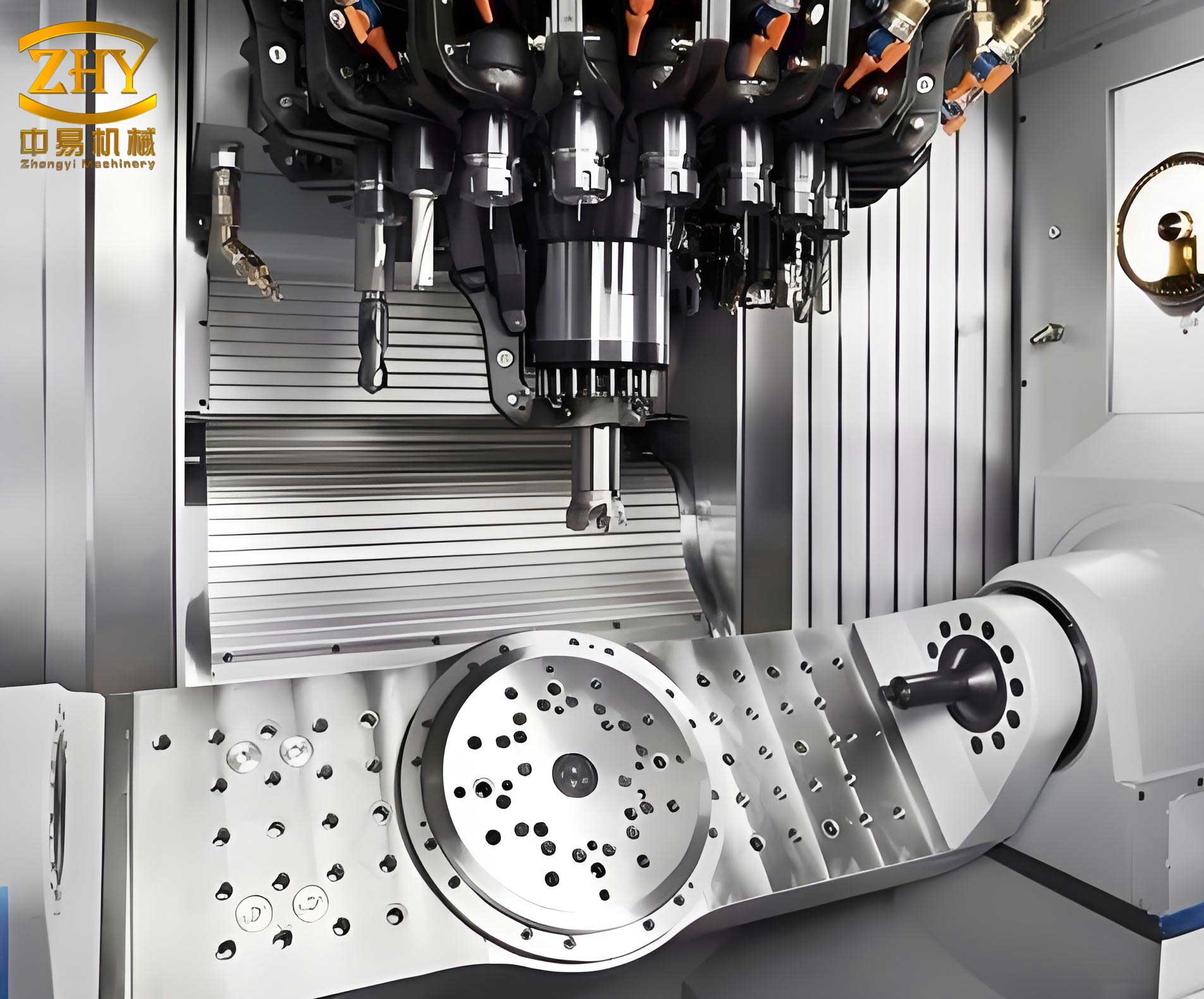
The software package encompasses multiple functional modules, as summarized in Table 1. These modules work cohesively to cover the entire process design cycle for machine tool castings, from initial data input to final documentation.
| Module | Primary Function | Key Features |
|---|---|---|
| Document Management | Manages drawing numbers, queries工艺 standards, and stores工艺 procedures. | Enables追加 and deletion of drawing numbers; displays工艺规程 as slides for reference. |
| Part Drawing Creation | Establishes or imports base drawings for machine tool castings. | Integrates with CAD environment for easy modification and storage. |
| Process Design | Core module for designing工艺 parameters and layouts. | Includes sub-modules for weight calculation,工艺 analysis, parting surface determination, machining allowance annotation, core design, gating system design, and flask selection. |
| Graphical Output | Generates final工艺 drawings and documents. | Automates drawing annotation and symbol placement. |
| Flask and Template Design | Designs flasks and templates based on casting dimensions. | Optimizes flask size to minimize material waste and ensure proper molding. |
The工艺 design module is the heart of our system, responsible for automating critical steps in the process design for machine tool castings. As shown in Figure 1 (conceptually represented here), this module consists of several interconnected sub-programs, each addressing a specific aspect of工艺 design. The flow begins with weight calculation and proceeds through工艺 analysis, parting surface selection, machining allowance annotation, core design, gating system design, flask selection, and finally, the creation of a工艺 summary table. This structured approach ensures that all necessary parameters are considered systematically, reducing omissions and errors common in manual design.
Let’s explore each sub-module in detail, incorporating formulas and tables where applicable. Starting with weight calculation, accurate estimation of the casting weight is crucial for determining material requirements and后续 design steps. For machine tool castings, which often feature complex shapes, we developed a versatile weight calculation program. It handles both basic geometric shapes (e.g., cylinders, cubes) and composite shapes commonly found in machine tool components. The weight \( W \) can be computed using the formula:
$$ W = \sum_{i=1}^{n} V_i \cdot \rho $$
where \( V_i \) is the volume of each geometric segment, and \( \rho \) is the density of the casting material (e.g., cast iron, typically around 7.2 g/cm³). For composite shapes, we categorized common configurations in machine tool castings, such as L-shaped brackets or T-slots, and derived simplified volume formulas. For instance, a common composite shape in bases or columns can be approximated as a combination of rectangular prisms and cylinders. The program prompts users to input parameters like length \( L \), width \( W \), height \( H \), and radius \( R \), which are readily available from design drawings. For highly irregular machine tool castings, we implemented a numerical integration method that calculates weight based on cross-sectional areas along a defined axis. The accuracy of this software is within 3% for small castings and meets design requirements for large and medium-sized machine tool castings.
Following weight calculation, the工艺 analysis sub-module provides guidance based on the casting’s material, weight, maximum轮廓 dimensions, and structural type. We classified machine tool castings into several types (e.g., Type A for slide seats, Type B for columns) and embedded expert rules into the database. For example, if a casting is identified as a “slide seat” with large flat surfaces, the program might recommend using chilling or specific riser placements to prevent shrinkage defects. This analysis draws from accumulated experience and standard工艺 procedures, helping novice engineers make informed decisions. Table 2 summarizes common analysis outcomes for different types of machine tool castings.
| Casting Type | Typical Geometry | Key工艺 Considerations | Recommended Actions |
|---|---|---|---|
| Slide Seat | Flat, elongated with导轨 surfaces | Minimize distortion; ensure hardness on wear surfaces | Use对称 gating; apply chills; select appropriate alloy |
| Column | Tall, vertical with internal cavities | Prevent hot tears; maintain dimensional stability | Employ vertical parting; design robust cores; control cooling rate |
| Base | Large, box-like with mounting points | Avoid shrinkage porosity; ensure rigidity | Implement bottom gating; use multiple risers; optimize wall thickness |
| Headstock | Complex with bearing housings | Achieve precise tolerances; reduce segregation | Apply controlled solidification; use inoculants; design precise cores |
The determination of the parting surface is a critical step in the process design for machine tool castings, as it influences moldability, core usage, and overall quality. Our program offers a variety of parting surface symbols, each coded for easy selection. Users are prompted to specify two endpoints on the parting surface via the CAD interface, after which the program displays a slide show of symbol options. Once a code is chosen, the software automatically draws the corresponding parting symbol on the drawing. Additionally, if the parting surface requires machining, the program can annotate machining lines and allowances accordingly. This automation ensures consistency across designs and reduces the time spent on repetitive symbol placement.
One of the most transformative sub-modules is the machining allowance annotation program. In manual design for machine tool castings, engineers must identify all machining symbols on the drawing and decide whether to allocate machining allowances, often leading to omissions or inconsistent values. Our program addresses this by automatically searching for machining symbols in the图形 database. Each symbol is highlighted and centered on the screen, prompting the user to confirm if machining is needed. If yes, the program retrieves allowance values from a database based on the casting’s maximum轮廓 dimensions and the orientation of the machining surface (e.g., top, bottom, side, or inclined). The allowance \( A \) can be expressed as a function of the casting dimension \( D \) and orientation factor \( k \):
$$ A = k \cdot f(D) $$
where \( f(D) \) is a standard allowance lookup table derived from工厂 standards. For example, for a large machine tool casting base, top surfaces might have an allowance of 5-8 mm, while sides have 4-6 mm, depending on dimensions. The program then automatically annotates the allowance value and draws machining示意 lines. We categorized machining lines into five types, as shown in Figure 2 (conceptually), and developed a sub-program that requires only 2-3 parameters from the user to draw the appropriate line. This not only prevents遗漏 but also standardizes allowance values across all machine tool castings designs.
Core design for machine tool castings is particularly challenging due to their complex internal geometries. To accommodate this, we developed 10 distinct core design types, covering common configurations like cylindrical cores, rectangular cores, and tapered cores. Users select a type based on the casting shape and工艺 requirements, then input parameters such as core length, diameter, and draft angles. The program automatically generates core designs, including core prints, clearances, venting provisions, core sequencing numbers, and ramming directions. Core print dimensions are calculated using empirical formulas to ensure proper support and alignment. For instance, the core print length \( L_p \) for a cylindrical core can be derived from:
$$ L_p = \alpha \cdot D_c + \beta $$
where \( D_c \) is the core diameter, and \( \alpha \) and \( \beta \) are coefficients based on the core material and molding method. This automation expands the software’s applicability to a wide range of machine tool castings, from simple to intricate designs.
The gating and risering system design is vital for achieving sound machine tool castings, as improper gating can lead to defects like turbulence, shrinkage, or inclusions. Our program automates this based on the casting weight, structural dimensions, and factory standards. It selects gating types (e.g., sprue, runner, ingate) and riser configurations from a database, calculating cross-sectional areas using hydraulic principles. For example, the choke area \( A_c \) for a pressurized gating system can be estimated with:
$$ A_c = \frac{W}{\rho \cdot t \cdot v \cdot C_d} $$
where \( W \) is the casting weight, \( \rho \) is metal density, \( t \) is pouring time, \( v \) is flow velocity, and \( C_d \) is a discharge coefficient. The program then prompts users to specify locations on the drawing, and it automatically annotates the gating system with standard symbols. This ensures optimal feeding and minimizes defects in machine tool castings.
Flask selection is another optimized feature. For machine tool castings, which often require large flasks, manual selection often results in either insufficient mold wall thickness (leading to defects) or excessive material use (causing waste). Our program calculates the required mold wall thickness based on casting dimensions, gating system space, and core print extensions, then queries a flask database to find the most economical standard flask size. The selection criterion minimizes the difference between required and available flask dimensions, ensuring cost-effectiveness without compromising quality.
Finally, the工艺 summary table module compiles all design parameters into a standardized table. It自动 reads data from temporary design files and populates a pre-formatted table block,生成 a comprehensive document that includes casting weight, material, flask size, core details, gating specifications, and machining allowances. This automates documentation, promoting consistency and ease of reference for production teams.
To illustrate the application of our software package for machine tool castings, let’s consider the design of a slide seat casting—a common component in combination machines. The process begins with weight calculation: inputting dimensions such as length=1500 mm, width=800 mm, height=500 mm, and wall thickness=20 mm, the program computes a weight of approximately 1200 kg using composite shape formulas. Next,工艺 analysis identifies it as Type A, recommending symmetrical gating and chills for flat surfaces. The parting surface is determined by selecting endpoints along the central plane, and the program draws a parting symbol automatically. Machining allowances are then annotated: for instance, top surfaces receive 6 mm, sides 5 mm, based on the maximum轮廓尺寸 of 1500 mm. Core design involves selecting Type 3 and Type 7 cores for internal cavities, with parameters like core diameter=100 mm and length=300 mm. The gating system is designed as a sprue-runner-ingate system with a choke area of 12 cm², and risers are placed at hotspots. Flask selection yields a standard size of 2000 mm × 1000 mm × 600 mm. All these steps are integrated, resulting in a complete工艺 drawing for the slide seat, as partially shown in a conceptual figure. This example demonstrates how the software streamlines design for machine tool castings, reducing manual effort and ensuring accuracy.
The development and application of this software package have yielded significant benefits for the process design of machine tool castings. Firstly, it dramatically reduces manual绘图 workload and enhances design speed, meeting the demands of small-batch, multi-variant production typical for machine tool castings. This acceleration shortens design and trial cycles, allowing products to reach the market faster. Secondly, it transforms traditional手工设计 into a computer-aided approach, improving design quality and achieving standardization across all machine tool castings designs. Consistency in工艺 parameters reduces variability in production, leading to higher quality castings. Thirdly, the embedded databases for graphics,工艺 standards, and procedures enable scientific document management, preserving expertise for future generations. However, we acknowledge limitations due to current AI capabilities and矢量化 software constraints; for instance, fully automated shape recognition remains challenging. As artificial intelligence advances, we anticipate further automation in process design for machine tool castings, making CAD systems even more intuitive and effective.
In conclusion, our software package represents a leap forward in the process design for machine tool castings. By automating key steps—from weight calculation and工艺 analysis to gating design and documentation—it addresses the inefficiencies of manual methods while promoting consistency and quality. The integration of tables, formulas, and database management ensures that design decisions are data-driven and repeatable. As the manufacturing industry evolves, such tools will become indispensable for producing high-quality machine tool castings efficiently. We are committed to refining this system, incorporating feedback from real-world applications, and exploring AI enhancements to further revolutionize the field. The journey toward fully automated process design for machine tool castings is ongoing, and we are proud to contribute to this transformative progress.