
In the foundry of machine tool castings, there is a familiar and often frustrating experience: a specific location on a casting consistently develops the same defect. When the root cause is correctly identified, the solution can be swiftly implemented. However, when the diagnosis misses the mark, the defect recurs persistently, leading to significant scrap losses and production headaches. The geometry of machine tool castings is typically complex, with substantial local variations in wall thickness. Due to the inherent structural design of the part or sometimes suboptimal gating system layout, molten iron can become stagnant in isolated pockets. This results in localized low-temperature metal, highly susceptible to consistent defects like gas holes and slag inclusions. Often, these flaws are not visible in the rough casting and only reveal themselves during machining, leading to the costly rejection of a nearly finished component.
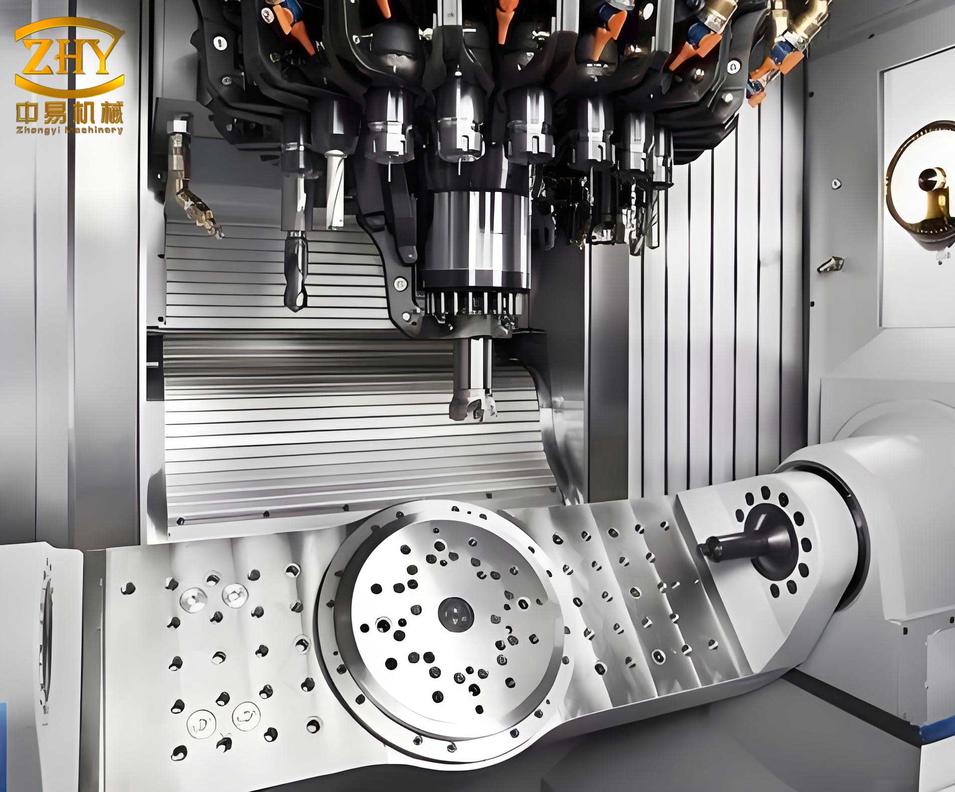
The journey to a sound casting begins with understanding the flow. The ability of molten metal to fill a mold cavity—its fluidity and mold-filling capacity—is paramount. High fluidity ensures the casting achieves its intended shape with sharp, clear contours. Furthermore, good fluidity promotes the upward flotation of gases and non-metallic inclusions, purifying the metal and yielding castings free from such defects. Within the iron-carbon system, gray cast iron exhibits excellent fluidity under standard pouring temperatures. This is primarily because its composition lies close to the eutectic point, resulting in a narrow freezing range and a less developed primary austenite dendrite network that impedes flow less than in other alloys.
However, “excellent” is not synonymous with “infallible.” For intricate machine tool castings, if process parameters such as pouring temperature or gate location are not meticulously controlled, the metal flow can still create isolated pockets. These pockets trap cooler, dirtier metal laden with slag and gases, inevitably leading to defective regions. The foundry engineer’s instinct might be to adjust the pouring temperature or redesign the entire gating system. While these are valid approaches, a powerful yet sometimes overlooked technique is the strategic use of “overflow.” The core concept is simple: design a channel that deliberately routes the contaminated, cold, and gas-entrapped metal from a critical area of the casting to a non-functional, sacrificial appendage. This “overflows” the problem away from the final part geometry. The implementation of this technique is highly versatile, tailored to the specific geometry and defect location of the machine tool casting, and is not confined to a single, rigid form.
Theoretical Foundations: Fluidity, Thermal Gradients, and Defect Formation
To appreciate the “overflow” solution, we must first delve deeper into the physics of casting defects in machine tool castings. The fluidity of molten iron is not a constant; it is a function of composition, temperature, and the mold’s thermal properties. As the metal flows through thin sections or long paths, it loses heat to the mold sand. When it finally reaches an isolated, thick section (like a mounting lug or a stiffening rib), its temperature may have dropped significantly, increasing its viscosity and reducing its ability to push impurities forward or vent gases back into the risers.
The localized cooling creates a severe thermal gradient. This area becomes a “thermal end” or a “cold spot” within the overall solidification pattern of the machine tool casting. Defects form here due to a confluence of factors:
- Gas Porosity: Gases dissolved in the molten metal are less soluble in the solid phase. As solidification initiates in this cold spot, gases are rejected and can form bubbles. With low fluidity and insufficient thermal energy to keep them in solution or allow them to migrate out, these bubbles become trapped as pinholes or larger cavities.
- Slag/Dross Inclusions: Oxides and other non-metallic particles (slag) carried by the melt have a tendency to float to the hottest metal surface. In a stagnant, cold pocket, the metal surface may solidify before these inclusions can float to a safe overflow or riser. They become entrapped within the casting wall.
- Shrinkage Porosity: Although often associated with hot spots, shrinkage can also manifest in poorly fed, isolated thick sections that solidify late but are not adequately supplied with liquid metal due to premature freezing of the feeding path.
The governing principle for fluidity length ($L_f$) in a channel can be approximated by considering the heat transfer:
$$L_f \approx \frac{v \cdot \rho_m \cdot [C_p (T_p – T_l) + L_f]}{2h (T_m – T_0)}$$
Where:
$v$ is the flow velocity,
$\rho_m$ is the metal density,
$C_p$ is the specific heat,
$T_p$ is the pouring temperature,
$T_l$ is the liquidus temperature,
$L_f$ is the latent heat of fusion,
$h$ is the heat transfer coefficient at the metal-mold interface,
$T_m$ is the average metal temperature $(T_p + T_l)/2$,
$T_0$ is the initial mold temperature.
This equation highlights that for a given mold and metal, the distance the metal can flow before stopping (the fluidity length) is highly sensitive to the superheat ($T_p – T_l$). In a complex machine tool casting, certain sections may receive metal that has traveled a long path through thin walls, effectively reducing its effective $T_p$ at that location, thereby drastically shortening its local $L_f$ and causing premature stopping or severe degradation of flow quality.
The “Overflow” Principle: A Proactive Diversion Strategy
The “overflow” technique directly attacks this problem. Instead of trying to force the cold, dirty metal to become part of a sound casting, we provide it with an easier escape route. Conceptually, the overflow acts as:
- A Thermal Sink: It becomes the coldest part of that local region, deliberately solidifying last and drawing the contaminated metal towards it.
- A Dirt Trap: Slag and oxides are carried by the metal flow into the overflow channel and become trapped there.
- A Gas Vent: Entrained air or evolved gases from the mold or core can escape through the overflow channel, often connected to a vent or open riser.
- A Flow Director: It alters the local solidification sequence, ensuring the critical part of the machine tool casting solidifies under a favorable temperature gradient, fed by cleaner, hotter metal.
The key design parameters for an effective overflow are its location, geometry, and connection to the casting. Its cross-section must be small enough to solidify quickly after performing its function (to minimize yield loss and cleaning effort) but large enough to not freeze off before drawing in the problematic metal. Often, its modulus (Volume/Surface Area ratio) is designed to be slightly greater than the section it is intended to protect, ensuring it remains liquid longer.
| Strategy | Principle | Advantages | Disadvantages/Limitations | Ideal Use Case |
|---|---|---|---|---|
| Increasing Pouring Temperature | Raises fluidity ($L_f$) system-wide. | Simple to implement; improves overall fill. | Higher risk of sand burn-in, veining, and enlarged grain size; increased energy cost. | General thin-section fill issues. |
| Redesigning Gating System | Alters flow path and thermal distribution. | Can provide a fundamental, robust solution. | Time-consuming; may require new pattern equipment; not always feasible. | Recurrent major filling or shrinkage defects. |
| Applying Chills | Locally increases cooling rate to eliminate isolated hot spots. | Very effective for shrinkage porosity; uses existing patterns. | Can over-chill and cause hard spots or cracks; adds process step. | Localized shrinkage in thick sections. |
| Overflow Technique | Diverts cold, contaminated metal away from critical area. | Highly targeted; low cost; uses existing patterns; excellent for gas/slag. | Adds cleaning work; minor yield loss; requires intelligent placement. | Localized cold spots prone to gas/slag entrapment (e.g., high isolated lugs). |
Implementation Case Studies in Machine Tool Castings
1. Application at the “Vise Jaw” Location on Saddle and Rotary Table Castings
Components like machine saddles and rotary tables often feature a “vise jaw” or钳口 structure, which houses the lead screw. The dimensional accuracy and soundness of this internal feature are critical, as any subsurface defect can compromise the machine’s precision. In traditional practice, this jaw feature is oriented upwards at the cope surface. Its structure is characterized by two thin walls, which, after machining allowance is added, often create a sharp corner at the top. A flat vent or small riser is typically placed here. However, defects such as blows (from insufficient core or mold venting), sand inclusions, and slag traps frequently occur due to issues with coating dryness, improper vent placement, or inadequate ramming around the core.
Overflow Solution: Instead of placing a riser directly on the fragile top edge of the jaw, an overflow channel is created by extending the core print (or creating a small sand extension) laterally from the highest point of the jaw’s side walls. A bottle-shaped riser is then placed on top of this horizontal channel. During pouring, metal flows through the jaw cavity and then into the overflow channel before reaching the riser. This offers several advantages: it is operationally simple, it moves the point of potential gas and slag collection away from the critical geometry, and it provides a more robust sand mass for placing the riser, reducing the risk of runouts or burned-in sand. The overflow channel thickness is typically designed not to exceed 10mm to prevent excessive metal loss and facilitate easy removal during cleaning without damaging the casting.
2. Application at the Foundation Feet (Leveling Pads) of Bed and Base Castings
Bed and base machine tool castings invariably incorporate foundation feet or leveling pads for bolt-down installation. While the integrity requirements are slightly less stringent than for guideways, defects here are still unacceptable. Standard practice is to orient the casting with the critical guideway surface down and the feet near the parting line in the cope. Duck-bill or bottle-shaped risers are placed on these feet for venting and minor feeding. Variations in pattern equipment, core assembly, and molding operations can lead to blows, sand washes, or even micro-shrinkage in these feet.
Overflow Solution: The direct riser on the foot is eliminated. Instead, an overflow channel is run horizontally from the side of the foot, along the parting plane, and a riser is placed at its end. This effectively “relocates” the riser by adding a short bend. This simple change addresses issues caused by poor riser contact or erosion of sand directly above the foot. Furthermore, if shrinkage is a concern due to metallurgical or head pressure variations, a chill can now be easily and effectively placed directly on the top surface of the foot itself, which was previously occupied by the riser. The design follows modulus calculations:
$$M_{riser} : M_{channel} : M_{foot} \approx 1.2 : 1.1 : 1.0$$
The channel thickness is also calibrated against the foot thickness to ensure it breaks off cleanly during knockout without tearing metal from the casting.
3. Application at Motor Mount Lugs on “L”-Shaped Machine Beds
A particularly challenging case involved a series of “L”-shaped bed castings where the motor mount lugs consistently exhibited sub-surface slag and gas holes revealed during machining. Solidification simulation (temperature field analysis) clearly identified these lugs as the coldest regions in the entire casting, isolated from the main thermal masses. The low-temperature metal arriving last at these points had poor fluidity, allowing all carried impurities to settle and gases to evolve.
Overflow Solution: A highly localized and minimalist overflow was implemented. Ceramic wash tubes (pre-formed refractory channels) were embedded in the sand mold, connecting the top of each problematic lug to a small, shared scrap extension or directly to the edge of the casting cavity. These tubes provided a low-resistance path for the final, cold, and dirty metal to be siphoned away from the lug, effectively linking the lug’s solidification to the larger thermal mass of the bed and restoring a healthier thermal gradient. This targeted application successfully eliminated the defects with minimal added yield loss.
Expanding the Concept: Other Applications in Machine Tool Castings
The utility of the overflow principle extends beyond the three primary cases mentioned. It is a versatile tool in the foundry engineer’s kit for machine tool castings.
- Guideway End Overflow Wells: The ends of long, thin guideways can sometimes be difficult to feed and vent. A small overflow well or “wash” at the very end of the guideway, beyond the finished part length, ensures that the metal flow continues, carrying any final slag or cold metal past the critical surface.
- Overflow at Lead Screw Bore Bosses: Similar to motor mounts, bosses surrounding lead screw holes can be thermal isolators. An overflow channel from the top of the boss to a riser or the casting perimeter can prevent shrinkage or gas holes.
- Overflow for Complex Internal Cavities: For castings with deep, enclosed cavities (e.g., inside column structures), creating an overflow exit at the highest point of the internal core assembly can be crucial for venting gases and ensuring complete filling, acting as a controlled leak path to verify cavity fill.
| Overflow Type | Typical Location | Key Geometry | Connection Modulus Ratio (Overflow:Casting Section) | Primary Function |
|---|---|---|---|---|
| Lateral Channel + Riser | High, isolated thin walls (Jaws) | Channel: Flat, 8-12mm thick. Riser: Bottle-shaped. | 1.1 : 1.0 | Divert gas/slag from fragile edge; provide venting. |
| Parting-Line Side Channel | Foundation Feet, Leveling Pads | Channel: Rectangular, thickness ~0.8x foot thickness. Riser at end. | Channel: 1.05 : 1.0, Riser: >1.2 : 1.0 | Relocate riser to enable chilling; prevent top-surface defects. |
| Embedded Ceramic Tube | Small, high isolated lugs/bosses | Tube ID: 1.5x to 2x lug thickness. Short, direct path. | N/A (Flow path, not a feeder) | Provide escape for cold, contaminated metal from micro-cold spot. |
| End Wash / Scrap Extension | End of guideways, rib intersections | Small rectangular or cylindrical appendage. | ~1.0 : 1.0 | Ensure flow continuity; trap terminal slag. |
Integrating Overflow Design into Systematic Process Planning
For optimal results, the use of overflow should not be an afterthought but integrated into the initial process design phase for machine tool castings. Modern simulation software plays a crucial role in this. By analyzing fill patterns and solidification sequences, potential cold spots and last-fill areas can be identified proactively. The engineer can then virtually test the placement and size of overflow channels to observe their effect on the temperature field and defect prediction metrics. This simulation-led approach transforms overflow application from a troubleshooting trick into a predictive, precision tool.
The effectiveness of an overflow system can also be analyzed by considering the pressure differential and flow dynamics at the junction between the casting and the overflow. Bernoulli’s principle and the concept of minimizing flow resistance are key. The overflow path should present a lower flow resistance than the path that would lead the contaminated metal deeper into the critical section of the machine tool casting. This can be influenced by the overflow’s cross-sectional area, length, and orientation relative to the metal flow direction.
Conclusion and Perspective
The production of high-integrity gray iron machine tool castings demands meticulous attention beyond mere dimensional accuracy. Internal soundness, free from localized gas and inclusion defects, is non-negotiable for the stability and performance of the final machine tool. This article has detailed a focused technical strategy—the “overflow” technique—for resolving defects arising from poor local fluidity and isolated cold spots. The method works on the principle of diversion, strategically relocating the problem from the functional casting geometry to a sacrificial appendage.
Key conclusions are as follows:
- The casting process for machine tool castings must account for severe thermal gradients caused by drastic wall thickness variations. These gradients can lead to localized degradation of fluidity, resulting in gas, slag, and shrinkage defects, particularly where metal flow becomes stagnant.
- The “overflow” technique is a targeted and highly effective solution for such problematic areas in machine tool castings. Its purpose is to create a preferential path for cold, impurity-laden metal to exit, thereby preserving the integrity of the critical casting section. Applications extend to guideway ends, screw bore bosses, and complex internal cavities.
- From a purist’s perspective, needing an overflow might indicate an inherent thermal imbalance in the casting design or initial process layout. In this sense, it could be considered a corrective measure. However, from a practical engineering standpoint focused on achieving a defect-free, high-quality casting reliably and cost-effectively—especially when modifying the component design or major tooling is not feasible—it represents an excellent and often optimal strategy. Its value in safeguarding the quality of complex machine tool castings makes it a technique worthy of mastery and thoughtful application in the foundry industry.
The ongoing evolution of simulation tools will further refine the precision of overflow design, allowing for its even more proactive and optimized use in the manufacture of demanding machine tool castings. It remains a testament to the principle that in foundry engineering, sometimes the best way to keep a casting clean is to show the impurities the door.