
In my extensive experience within the foundry industry, particularly specializing in the production of high-grade machine tool castings for domestic and international markets, crack defects remain one of the most persistent and costly challenges. These defects, characterized by their strong regularity and potential to cause large-scale scrap, pose a significant threat to production efficiency and economic viability. The increasing demand for exported, thin-walled, and structurally rigid machine tool castings, often specified with high-grade iron (HT250 and above), combined with inherent design complexities—such as significant variations in wall thickness and stringent hardness requirements on massive sections like guideways—has substantially elevated the technical difficulty of production. Failures to overcome these technical hurdles or deviations in quality assurance processes frequently lead to the occurrence of cracks, resulting in considerable losses.
Cracks in grey iron machine tool castings typically manifest in several forms: internal cracks within heavy sections, external cracks on relatively thin walls, and most commonly, external cracks at transition zones where thick and thin sections connect. Based on their nature and formation mechanism, cracks are classified into two primary categories: hot tears, which occur during solidification due to phase transformation and contraction stresses, and cold cracks, which form during the solid-state cooling phase after solidification is complete. From a root-cause perspective, cracks can be further detailed into four distinct types, as summarized in the table below.
| Type | Primary Cause | Typical Manifestation & Location | Nature |
|---|---|---|---|
| 1 | Unfavorable Component Design (Structural) | External cracks at thick-thin transition zones. | Cold Crack (Primarily) |
| 2 | Unfavorable Flash (Fin) Design (Process) | External cracks initiating in the flash and propagating into the casting body. | Cold Crack |
| 3 | Detrimental Iron Chemistry / Poor Inoculation (Metallurgical) | Internal cracks in heavy sections or external cracks on thin walls; related to localized chill. | Hot Tear & Cold Crack |
| 4 | Insufficient Cooling-in-Mold Time (Operational) | Deep, often through-section, external cracks. | Cold Crack |
From practical observation, the vast majority of cracks in machine tool castings are cold cracks. However, a pronounced tendency for hot tearing will invariably increase the susceptibility to cold cracking. Therefore, the prevention strategy must be two-pronged: cold cracks are primarily addressed by achieving uniform cooling of the casting, while hot cracks are mitigated by improving iron quality—specifically by reducing harmful elements, decreasing section sensitivity, and refining the graphite structure.
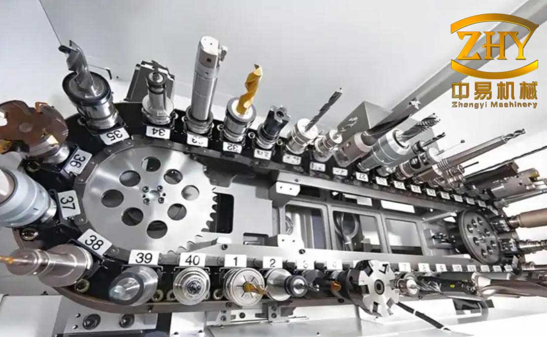
The structural complexity of machine tool castings, as illustrated, inherently creates areas of stress concentration. Transition zones are critical because the thin section solidifies and begins to contract first, while the adjoining heavier section remains liquid or mushy. As the heavier section subsequently solidifies and contracts, it pulls on the already solid thin section, generating tensile stresses ($\sigma_t$) that can exceed the material’s high-temperature strength, leading to a hot tear, or its room-temperature strength, causing a cold crack. The stress at such a junction can be conceptually related to the differential contraction:
$$\sigma_t \propto E \cdot \alpha \cdot \Delta T \cdot \Phi(A_t, A_h)$$
where $E$ is Young’s modulus, $\alpha$ is the coefficient of thermal contraction, $\Delta T$ is the effective temperature difference between the sections during critical cooling stages, and $\Phi$ is a function dependent on the cross-sectional areas of the thin ($A_t$) and heavy ($A_h$) sections.
Root Cause Analysis and Lessons from Practice
My involvement in troubleshooting crack defects has provided concrete insights into each failure type. The following analysis synthesizes these experiences without referencing specific proprietary cases.
Type 1: Structural Cracks from Design
These cracks are a direct consequence of non-optimal casting geometry. A classic example involves thin connecting ribs or walls placed between larger masses. The ribs solidify rapidly and are then subjected to tensile pull from the slower-solidifying adjacent sections. Merely extending mold cooling time or increasing inoculation often fails to resolve this issue, as the fundamental problem is mechanical. The solution lies in modifying the pattern to reduce the stiffness imbalance. This typically involves thickening the vulnerable thin section and generously radiusing the connecting fillet. As a rule of thumb for high-grade machine tool castings (e.g., HT250), the minimum recommended wall thickness should be no less than 12-15 mm, and the cross-sectional area ratio between connected walls should ideally not exceed 1:1.5 to 1:2.
Type 2: Process Cracks from Flash Design
This is a particularly prevalent issue in modern foundries using chemically-bonded sands (like resin sand), which produce sharp, thin flashes. The flash, located at the mold parting line or core prints, cools extremely rapidly, often developing a fully chilled white iron structure with negligible strength and ductility. When this brittle flash is situated at a point of high casting stress (like the end of a guideway or a thin flange), the crack initiating in the flash easily propagates into the sound body of the machine tool casting. The key insight is that the flash itself becomes the failure origin. Countermeasures involve relocating the flash away from high-stress areas or, more effectively, modifying the flash design to reduce its chilling tendency. One proven method is to incorporate a “breakwall” or a thickened section adjacent to the casting at the flash location. This “buffer” section cools slower, retains a grey iron structure, and can accommodate contraction stress without fracturing, thereby protecting the casting.
Type 3: Metallurgical Cracks from Iron Quality
The chemical composition and liquid treatment of the iron are paramount. Excessive levels of certain elements, notably sulfur (S) and phosphorus (P), severely increase hot tearing and cold cracking susceptibility. Phosphorus forms a brittle, low-melting-point phosphide eutectic that segregates to grain boundaries, weakening them. High sulfur content adversely affects graphite morphology and can promote chill. Furthermore, inadequate or ineffective inoculation fails to counteract the chilling tendency, especially in thin sections or at flash locations, leading to hard, crack-prone zones. The problem is exacerbated when alloying elements (like Cr or Sn) are added to boost hardness without proper foundation in base iron quality and inoculation. A critical indicator is the presence of chill or mottled structure in the wedge or chill test sample; if more than 10-15% chill is observed, the corresponding castings are at high risk for cracks. The target chemistry and treatment parameters are summarized below:
| Parameter | Target / Limit for Cupola-Melted Iron | Rationale |
|---|---|---|
| Phosphorus (P) | ≤ 0.10% (ideally ≤ 0.08%) | Minimizes brittle phosphide network. |
| Sulfur (S) | ≤ 0.12% | Reduces chill tendency, improves inoculation response. |
| Inoculation (FeSi) | 0.2% – 0.5% (post-inoculation) | Ensures graphite formation, reduces section sensitivity. |
| Alloying (e.g., Cr) | ≤ 0.3% (avoid in low-temp iron) | Prevents excessive chilling and carbide stability. |
| Carbon Equivalent (CE) | ~4.0 – 4.2 | Balances strength, castability, and reduced shrinkage stress. $CE = \%C + \frac{1}{3}(\%Si + \%P)$ |
Type 4: Operational Cracks from Premature Knock-out
This is often the simplest cause to diagnose but can be the most damaging. If a machine tool casting is removed from the molding sand while its interior is still at a significantly elevated temperature (e.g., above 400-500°C), the rapid and uneven cooling in air induces severe thermal stresses. These stresses can superimpose on the residual casting stresses, leading to catastrophic cracks that are often long and deep. The required cooling-in-mold time is not arbitrary; it is a function of the casting’s thermal mass, geometry, and molding material. It should be sufficient for the casting to cool to a temperature where its strength can withstand the handling and ambient cooling stresses, typically below 200-250°C.
Systematic Countermeasure Strategy
Based on the analysis above, a successful strategy to minimize cracks in machine tool castings involves a coordinated approach across design, metallurgy, and process engineering.
1. Design and Communication for Producibility
Foundries must actively collaborate with designers. For castings requiring high strength (HT250+), advocating for design rules is essential: minimum wall thicknesses of 12-15mm, generous fillet radii (R>10mm), and avoidance of drastic section changes. Where heavy sections like guideways are necessary for function, proposing alternatives like inserted steel guideways can eliminate the massive thermal hub and associated cracking risks.
2. Metallurgical Control and Iron Treatment
This is the cornerstone of crack prevention. Key actions include:
- Maintain High Carbon Equivalent (CE): Aim for a CE in the range of 4.0-4.2. This promotes good fluidity, reduced shrinkage tendency, and lower internal stress. The formula is fundamental: $$CE = C + \frac{1}{3}(Si + P)$$
- Stringent Control of Harmful Elements: Implement strict charge control to keep P and S levels as low as practically possible, recognizing the hereditary effect of returns.
- Robust and Effective Inoculation: Use sufficient amounts of effective inoculant (e.g., FeSi75) treated with modern carriers like Sr, Ca, or Ba for longer fading resistance. Inoculation must be performed as late as possible before pouring.
- Cautious Alloying: Avoid alloying additions to low-temperature iron. If hardness must be increased, prioritize high CE and effective inoculation first. Use micro-alloying rather than bulk additions.
3. Foundry Process Optimization
The gating and feeding system should promote directional solidification. Crucially, special attention must be paid to the design of flashes and core prints in resin sand molds. The principle is to avoid creating a brittle, chill-prone geometry at stress points. Techniques include:
- Relocating parting lines away from critical areas.
- Designing “breakwalls” or dummy ribs next to the casting at flash locations to act as stress buffers.
- Increasing the draft or thickness of the flash locally to reduce its cooling rate.
4. Uncompromising Adherence to Cooling Parameters
Establish and strictly enforce minimum cooling-in-mold times based on the molding medium and casting weight/section. The following table provides generalized guidelines, but plant-specific trials are necessary for optimization.
| Molding Medium | Typical Min. Cooling-in-Mold Time* | Governing Factor |
|---|---|---|
| Green Sand | 2 – 4 hours | High cooling rate allows shorter times for small/medium castings. |
| Clay-Dry Sand | 8 – 12+ hours | Lower thermal conductivity requires longer times to reach safe temperature. |
| Resin-Bonded Sand | 12 – 24+ hours | Excellent thermal insulation means very slow cooling; premature knock-out is extremely risky. |
The scientifically determined time should be based on the casting cooling to a temperature near the ambient (e.g., <200°C) inside the mold. This time ($t_{cool}$) can be estimated using empirical relations considering casting mass ($M$), modulus ($V/A$), and pouring temperature ($T_p$):
$$ t_{cool} \approx k \cdot M^{2/3} \cdot \left(\frac{V}{A}\right)^{-1} \cdot \ln\left(\frac{T_p – T_{mold}}{T_{safe} – T_{mold}}\right) $$
where $k$ is a medium-specific constant, $V/A$ is the volume-to-surface-area ratio (modulus), $T_{mold}$ is the initial mold temperature, and $T_{safe}$ is the target safe knock-out temperature.
In conclusion, the battle against cracks in high-grade machine tool castings is won through a holistic and disciplined approach. It requires a synergy of intelligent design review, meticulous metallurgical control focused on high CE and low impurities, ingenious process design that manages contraction at geometric discontinuities like flashes, and unwavering adherence to controlled cooling protocols. By systematically implementing this multi-faceted strategy, foundries can successfully contain the occurrence of these costly defects to minimal levels, ensuring the reliable production of high-quality, durable machine tool castings that meet the demanding standards of the global market.