
In the realm of heavy engineering, the demand for robust, high-integrity components is ever-present. Among these, shell castings designed to operate under severe conditions of high temperature, pressure, and thermal fatigue present a formidable manufacturing challenge. This is particularly true when these shell castings are produced in ductile iron (QT600-3) with substantial dimensions and thick sections. The primary hurdles involve preventing graphite deterioration, eliminating internal shrinkage, and achieving the required as-cast microstructure and mechanical properties consistently. This account details the comprehensive approach and precise control points necessary to successfully manufacture such large-scale shell castings, drawing from our direct experience in overcoming these significant production difficulties.
The specific component in question was a large pressure housing. Its demanding service environment necessitated high strength and considerable impact resistance. The sheer size and geometry of the casting itself set the stage for the challenges: a poured weight of approximately 15 tonnes, overall envelope dimensions of 4500 mm x 3500 mm x 600 mm, a nominal wall thickness of 100 mm, and a massive flange section reaching 400 mm in thickness. The quality benchmark was exceptionally high, requiring ultrasonic testing (UT) on the thick flange sections to meet a Grade II standard, free from shrinkage cavities, porosity, and inclusions. Producing such thick-section ductile iron shell castings risks several well-documented issues: degenerated graphite forms (e.g., chunky, exploded graphite), a drastic reduction in graphite nodule count, shrinkage porosity, coarse matrix structure, and severe segregation of alloying elements.
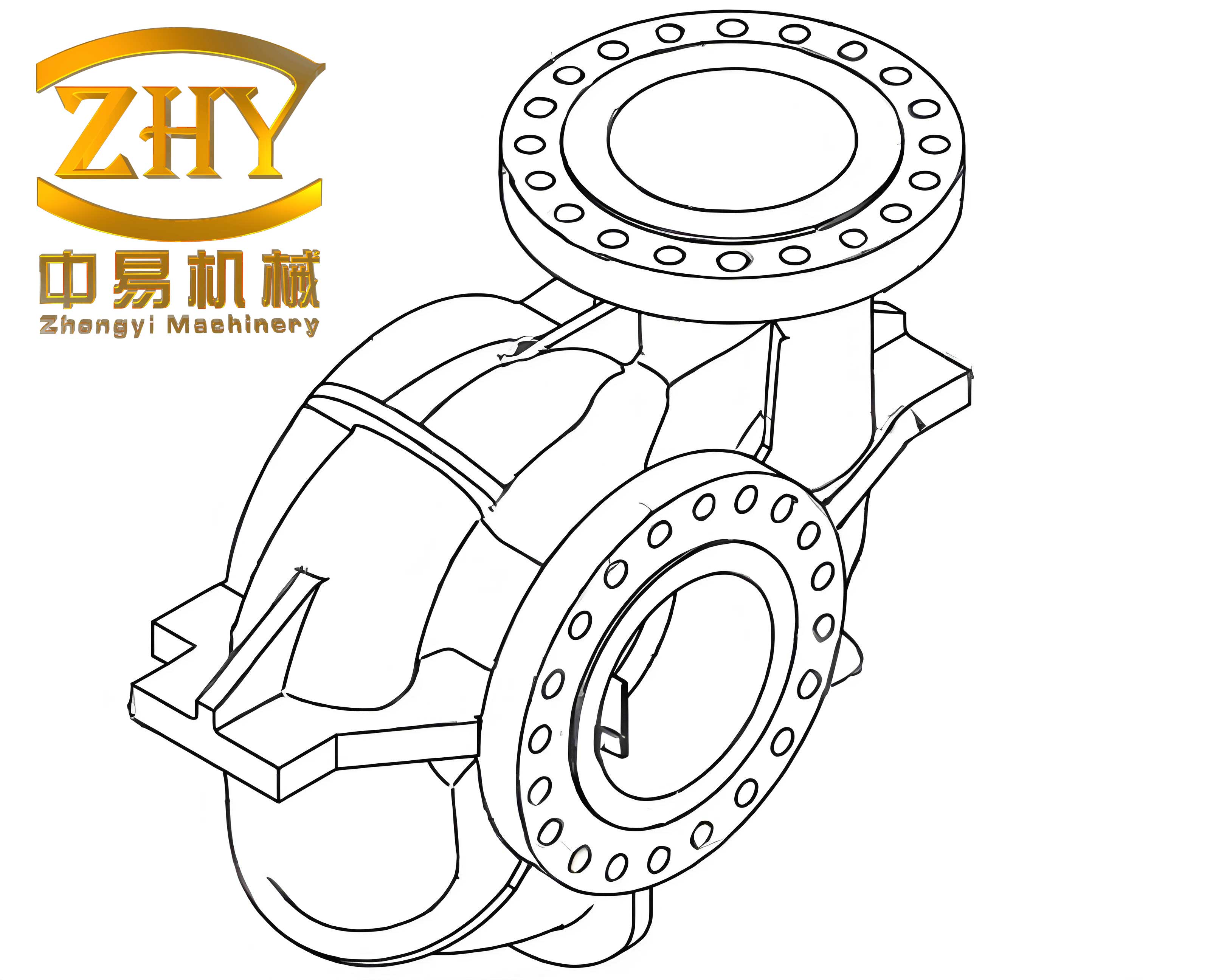
Technical Specifications and Core Production Challenges
The successful production was guided by strict technical specifications and a clear understanding of the associated risks.
| Parameter | Specification / Challenge |
|---|---|
| Material Grade | Ductile Iron QT600-3 |
| Key Microstructure | Nodularity Grade 1-3, Pearlite ≥ 90%, Carbides + Phosphide Eutectic ≤ 3% |
| Mechanical Properties | Tensile Strength ≥ 600 MPa, Elongation ≥ 3%, Impact Value ≥ 7 J, Hardness ≥ 190 HB |
| Dimensional Control | CT11 grade, verified via coordinate measuring machine (CMM). |
| Integrity Requirement | Ultrasonic Testing (UT) Grade II on thick flange sections. |
| Primary Challenge 1 | Preventing graphite nodule degeneration in heavy sections (≥400mm). |
| Primary Challenge 2 | Achieving soundness (no shrinkage) in heavy sections for UT qualification. |
| Primary Challenge 3 | Securing ≥90% pearlitic matrix in the as-cast state for strength. |
Foundry Process Design and Control
The entire manufacturing process, from pattern making to mold assembly, was tailored to ensure dimensional accuracy, stability, and controlled solidification.
Pattern and Mold Engineering
Given the large size and complex geometry, the pattern was CNC-machined from high-grade, dimensionally stable laminated board to guarantee accuracy and durability. A shrinkage allowance of 0.8% was applied. The molding process utilized furan resin-bonded sand for both molds and cores, chosen for its high dimensional accuracy, excellent surface finish, and high strength. Cores and molds were compacted to high density. A zircon-based alcohol-fast drying coating was applied with a controlled thickness of 0.6-1.5 mm to further enhance surface quality.
Gating and Feeding System Strategy
The design philosophy centered on controlled filling and directional solidification to promote soundness. The gating system was strategically placed away from the thickest sections, instead utilizing multiple ingates at the lower parts of the casting’s rib network. This promoted multi-stream, tranquil filling to maintain uniform temperature distribution and support a balanced solidification front. The gating ratio was set as:
$$ \Sigma F_{\text{sprue}} : \Sigma F_{\text{runner}} : \Sigma F_{\text{ingate}} = 1.5 : 2.0 : 1.0 $$
Eight uniformly distributed vent/atmospheric risers were placed on the top of the casting to aid mold evacuation and act as pressure relief points.
Chill Design and Solidification Control
This was the most critical aspect for ensuring soundness and microstructure in the heavy flange sections. External chills were strategically placed on the thick flange faces. Their purpose was twofold: to accelerate the local cooling rate, thus refining the microstructure and suppressing abnormal graphite formation, and to establish a favorable thermal gradient for directional solidification towards the riserless body of the casting. The chill thickness was calculated as a function of the thermal section modulus, typically:
$$ T_{\text{chill}} = (0.5 \text{ to } 0.6) \times \delta $$
where \( \delta \) is the diameter of the thermal hot spot. The goal was to control the solidification time, allowing the well-known graphitization expansion of ductile iron to effectively compensate for the liquid and early solidification shrinkage, achieving what is often termed “self-feeding.” The success of this method relies on a strong, rigid mold to contain the expansion pressure and direct it inward to feed the remaining liquid.
Metallurgical Control for Heavy-Section Shell Castings
The chemistry and treatment of the molten iron are paramount in determining the final properties and graphite morphology, especially in slow-cooling thick sections.
Raw Material Selection and Charge Design
High-purity charge materials are non-negotiable. Trace elements like Pb, Sb, Ti, and V, which strongly promote graphite degeneration, were strictly controlled. The charge consisted of:
Pig Iron: High-purity grades (e.g., Q10, Q12) with low residuals (Mn < 0.3%, P < 0.06%, S < 0.03%).
Steel Scrap: Low-carbon steel scrap (thickness ≥ 3mm) to dilute impurities.
Alloys: Yttrium-based heavy rare earth magnesium ferrosilicon (ZY-3B) was selected as the nodularizer for its superior fade resistance. A long-lasting inoculant was used for multiple-stage inoculation.
Melting and Duplexing Practice
A duplex melting process was employed, combining a 10 t/h cupola and a 20 t medium-frequency induction furnace. This method offers distinct advantages for high-quality shell castings:
1. It allows for a high scrap steel charge (up to 40%), reducing cost and, more importantly, lowering the phosphorus content and minimizing its negative impact on mechanical properties and shrinkage tendency.
2. It helps break the “genetic” inheritance from pig iron, promoting better graphite morphology and higher pearlite content.
3. It reduces the section sensitivity of the casting, leading to more uniform properties and lower residual stresses.
The cupola provided a consistent, high-temperature base iron, which was then transferred to the induction furnace for final superheating, composition adjustment, and desulfurization if necessary. Pre-treatment desulfurization using sodium carbonate (Na2CO3) was performed if the base iron sulfur exceeded 0.08%, directly reducing the required nodularizer addition.
| Element | Target Range (wt.%) | Function / Rationale |
|---|---|---|
| Carbon (C) | 3.6 – 3.9 | High carbon equivalent promotes graphitization, feeding via expansion. Counteracts chilling. |
| Silicon (Si) | 1.9 – 2.4 | Powerful graphitizer. Final content controlled via inoculation. Boosts strength. |
| Manganese (Mn) | < 0.30 | Kept low to minimize segregation and pearlite stabilization at boundaries. |
| Phosphorus (P) | < 0.03 | Kept very low to prevent phosphide eutectic, which embrittles the casting. |
| Sulfur (S) | < 0.02 | Kept extremely low post-treatment to minimize Mg consumption and dross. |
| Magnesium (Mg) | 0.03 – 0.05 | Residual after treatment. Essential for nodularity. Tight control prevents defects. |
| Rare Earths (RE) | 0.01 – 0.03 | Primarily from nodularizer. Counteracts harmful trace elements, improves nodule shape. |
Nodularization and Inoculation Practice
The treatment was performed using the sandwich method in a preheated ladle. The yttrium-based nodularizer (1.5-2.0% of tap weight) was placed in the bottom alongside desulfurizer. The metal was tapped in a single, rapid stream. A primary inoculation of 0.3-0.5% FeSi75 was added during tapping in the runner. Immediately after treatment, slag was thoroughly removed.
Inoculation is arguably the most critical metallurgical step for thick-section shell castings. It determines the final graphite nodule count, size, and roundness, directly influencing mechanical properties and shrinkage behavior. We employed a multi-stage inoculation strategy:
1. Primary (Stream) Inoculation: During tap, as described.
2. Late Inoculation: Additional inoculant (a high-efficiency compound) was added into the pouring box during casting. This “post-inoculation” counteracts fading and enhances nucleation in the latest solidifying regions.
The total inoculant addition was carefully controlled between 0.6% and 1.0%. The effectiveness was monitored via thermal analysis and wedge test samples, targeting a white fracture width of 12 mm in the base iron and 5-7 mm after treatment.
Pouring and Solidification
The final step, pouring, was executed with strict protocol. The pouring temperature was maintained between 1290°C and 1320°C. A fast yet smooth pour was essential to maintain thermal gradient and minimize oxide formation. A pouring box equipped with a ceramic foam filter was used to trap any remaining slag. The late-stage inoculant was introduced uniformly into the metal stream at this box. The combination of controlled pouring, effective chills, and a rigid mold allowed the graphitization expansion to be harnessed effectively, ensuring the internal soundness of the thick sections in these massive shell castings.
Results and Validation
The implementation of this controlled, integrated approach yielded consistently successful results across multiple production runs. The following table summarizes the results from a batch of castings, demonstrating compliance with the stringent specifications.
| Casting ID | Nodularity Grade | Pearlite Content (%) | (Carbides+Phosphides) (%) | Tensile Strength (MPa) | Elongation (%) | Hardness (HB) |
|---|---|---|---|---|---|---|
| 1 | 3 | 95 | <1 | 650 | 3.0 | 198 |
| 2 | 2 | 92 | <1 | 638 | 4.5 | 190 |
| 4 | 2 | 95 | <1 | 690 | 4.0 | 221 |
| 6 | 2 | 91 | <1 | 652 | 3.5 | 200 |
Metallographic examination revealed a microstructure dominated by fine, well-distributed graphite nodules (Grade 2-3) in a matrix consisting of over 90% pearlite, with negligible amounts of carbides or phosphide eutectic. This microstructure directly correlated with the excellent and consistent mechanical properties achieved in the as-cast condition. Most importantly, ultrasonic testing performed on the heavy flange sections of all produced shell castings confirmed their internal soundness, meeting the Grade II acceptance criteria with no reports of shrinkage defects, slag inclusions, or gas porosity. Furthermore, dimensional inspection via coordinate measuring machine verified all critical dimensions were within the CT11 tolerance.
Conclusion
The production of large, thick-section ductile iron shell castings with demanding mechanical and integrity requirements is a complex interplay of foundry engineering and metallurgical science. Success is not attributable to a single factor but to the rigorous control and synchronization of all process stages. Key takeaways include: the necessity of high-purity charge materials and a duplex melting practice; the critical selection of fade-resistant nodularizers and aggressive, multi-stage inoculation; the paramount importance of a rigid mold system combined with strategic chill placement to control solidification and harness graphitization expansion for feeding; and the precise management of pouring parameters. By systematically addressing each challenge—graphite degeneration, shrinkage soundness, and as-cast microstructure—through these integrated control points, it is demonstrably possible to reliably produce high-integrity large ductile iron shell castings that meet the most stringent industrial standards for performance and quality.