
In the field of heavy industrial manufacturing, the production of large ductile iron shell castings presents significant challenges due to their substantial thickness, complex geometries, and stringent performance requirements. These shell castings are critical components in applications such as pumps, valves, and pressure vessels, where they must withstand high temperatures, pressures, and thermal fatigue. This article details our comprehensive approach to successfully manufacturing large ductile iron shell castings, focusing on key control points in molding, gating and riser design, chilling, assembly, and melting processes. Our goal was to achieve castings that meet rigorous quality standards, including specific microstructural and mechanical properties, dimensional accuracy, and freedom from internal defects detectable by ultrasonic testing. Throughout this development, we emphasize the importance of managing graphite morphology, preventing shrinkage porosity, and leveraging graphitization expansion in thick-section shell castings.
The primary shell castings we aimed to produce had a轮廓尺寸 of approximately 4500 mm × 3500 mm × 600 mm, with a weight of around 15 tons upon pouring. The wall thickness was typically 100 mm, with flange areas reaching up to 400 mm. Such dimensions classify these as heavy-section ductile iron castings, where cooling rates are slow, leading to risks of graphite deterioration, reduced graphite nodule count, shrinkage porosity, coarse matrix structure, and elemental segregation. The material specification was QT600-3, requiring a tensile strength exceeding 600 MPa, elongation of at least 3%, and impact energy over 7 J, with a pearlite matrix content above 90% and minimal carbides and phosphide eutectic. Additionally, the flange surfaces required ultrasonic testing (UT) to Grade 2 standards, demanding high internal soundness. These requirements made the production of these shell castings a formidable task, necessitating a holistic and meticulously controlled manufacturing strategy.
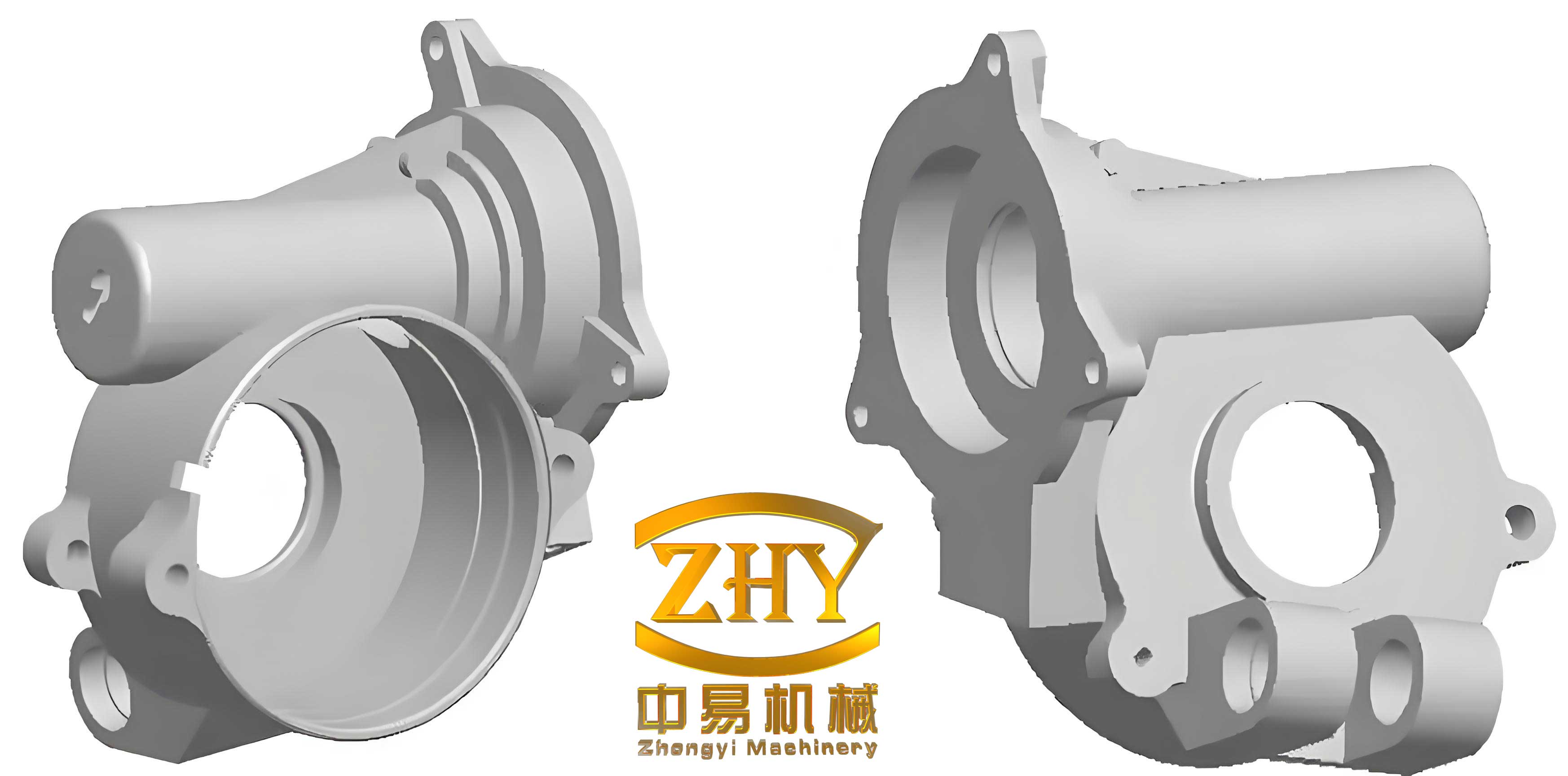
One of the core challenges in producing these large shell castings is controlling graphite morphology. In thick sections, the prolonged solidification time can lead to graphite flotation, chunk graphite, or vermicular graphite, severely degrading mechanical properties. The graphitization expansion that occurs during solidification must be harnessed effectively to counteract shrinkage and achieve self-feeding. Furthermore, ensuring a high pearlite content in the as-cast state without heat treatment is crucial for meeting strength requirements. To address these, we developed an integrated process covering pattern making, molding, gating, chilling, and melting, each tailored for heavy-section ductile iron shell castings.
Our pattern-making process for these large shell castings utilized imported multi-layer composite board materials to ensure dimensional stability, durability, and ease of stripping. Given the complex geometry and large size, we employed CNC milling for precision machining and used coordinate measuring machines (CMM) for verification. The pattern shrinkage allowance was set at 0.8% to compensate for the contraction of ductile iron during cooling. This careful pattern fabrication was essential to achieve the required dimensional accuracy of CT11 per digital arm measurement, which is critical for the final assembly and function of the shell castings.
For molding and coremaking, we adopted furan resin self-hardening sand due to its excellent dimensional accuracy and surface finish capabilities. The sand molds and cores were designed with adequate sand thickness to withstand metallostatic pressures and prevent deformation. High compactness was ensured to avoid mold wall movement, which could lead to dimensional inaccuracies or shrinkage defects. The surfaces were coated with a zircon-based alcohol-fast drying paint with a thickness of 0.6–1.5 mm to improve surface smoothness and prevent metal penetration. This molding approach is vital for producing shell castings with intricate details and tight tolerances.
The gating system design for these shell castings aimed to achieve uniform filling and temperature distribution. We avoided direct gating into thick sections to prevent localized hot spots. Instead, multiple gates were placed at the lower regions and distributed through reinforcing ribs to ensure multi-stream,平稳充型. This promotes simultaneous solidification and minimizes thermal gradients. The gating ratio was set as ΣFsprue : ΣFrunner : ΣFgate = 1.5 : 2 : 1, ensuring a non-turbulent flow that reduces slag inclusion and oxidation. The use of a filter in the pouring basin further enhanced metal cleanliness. Proper gating is fundamental for defect-free shell castings, particularly in preventing shrinkage and gas porosity.
Riser and chill design are critical for feeding and controlling solidification in thick-section shell castings. We placed eight evenly distributed vent risers on the top surfaces to allow gas escape and provide minor feeding. However, the primary feeding mechanism relied on graphitization expansion. To accelerate cooling in thick areas like flanges and prevent graphite degeneration, we employed chills. The chill thickness was determined as (0.5–0.6)δ, where δ is the热节 diameter (thermal node diameter). This accelerates solidification, refines the microstructure, and reduces the risk of shrinkage porosity. The strategic placement of chills helps in directing solidification fronts and maximizing the use of graphite expansion for self-feeding. This approach is encapsulated in the solidification time equation for a plate-like casting:
$$ t_s = \frac{V}{A} \cdot \frac{\rho L}{k (T_p – T_m)} $$
where \( t_s \) is solidification time, \( V \) is volume, \( A \) is surface area, \( \rho \) is density, \( L \) is latent heat, \( k \) is thermal conductivity, \( T_p \) is pouring temperature, and \( T_m \) is mold temperature. For our shell castings, reducing \( t_s \) in thick sections via chills was key to controlling graphite morphology.
To quantify the chilling effect, we can relate chill thickness to the cooling rate. The heat extraction rate \( Q \) from a chill can be approximated by:
$$ Q = h_c A_c (T_c – T_m) $$
where \( h_c \) is the heat transfer coefficient at the chill-casting interface, \( A_c \) is the chill area, \( T_c \) is the casting surface temperature, and \( T_m \) is the chill initial temperature. By optimizing chill design, we enhanced the cooling rate in critical zones of the shell castings.
The quality of large ductile iron shell castings heavily depends on melting and metallurgical control. We used a duplex melting process involving a 10 t/h冲天炉 (cupola) and a 20 t medium-frequency induction furnace. This combination allows for cost-effective melting with high scrap steel usage (up to 40%), reducing reliance on pig iron and minimizing harmful element inheritance. The raw materials were selected for high purity: pig iron with low Mn (<0.3%), P (<0.06%), and S (<0.03%) content, preferably Q10 or Q12 grades; and clean carbon steel scrap. This minimizes trace elements like Sb, Ti, V that promote graphite deterioration in thick sections.
Chemical composition is paramount for achieving the desired microstructure and properties in shell castings. Our target composition for the QT600-3 shell castings is summarized in Table 1.
| Element | Range | Role in Shell Castings |
|---|---|---|
| C | 3.6–3.9 | Promotes graphitization, affects fluidity and shrinkage |
| Si | 1.9–2.4 | Graphitizer, strengthens ferrite, influences pearlite formation |
| Mn | <0.3 | Minimized to reduce segregation and carbide formation |
| P | <0.03 | Kept low to avoid phosphide eutectic and brittleness |
| S | <0.02 | Low level essential for effective nodularization |
| RE (稀土) | 0.01–0.03 | Enhances nodularization and counteracts anti-spheroidizing elements |
| Mg | 0.03–0.05 | Key nodularizing element, controls graphite spheroidization |
Before treatment, the base iron sulfur content was kept below 0.08%. If higher, desulfurization was performed using sodium carbonate (Na2CO3) powder at 0.3–0.5% addition. The nodularization treatment used yttrium-based heavy rare earth alloy (ZY-3B) via the sandwich method in the ladle, with an addition of 1.5–2.0% of the tap weight. The reaction was controlled to be平稳, ensuring good Mg and RE recovery. Inoculation is critical for promoting fine, round graphite nodules in shell castings. We employed multi-stage inoculation with a long-lasting inoculant, totaling 0.6–1.0% addition. The primary inoculation (0.3–0.5% FeSi75) was done during tapping, followed by late-stream inoculation during pouring using a复合孕育剂 added to the pouring basin. The effectiveness of inoculation can be related to the graphite nodule count \( N \), which influences mechanical properties:
$$ N = k_I \cdot C_{Si}^{a} \cdot e^{-b/T} $$
where \( k_I \) is an inoculation constant, \( C_{Si} \) is silicon content, \( T \) is solidification temperature, and \( a, b \) are exponents. High \( N \) is desirable in shell castings to prevent graphite degeneration.
The pouring temperature was maintained at 1290–1320°C to ensure adequate fluidity while minimizing gas absorption and shrinkage. Fast but平稳 pouring was adopted to reduce temperature loss and oxidation. The use of a filter in the gating system helped trap slag. The cooling curve analysis during solidification is vital for predicting microstructure. For ductile iron, the eutectic undercooling \( \Delta T_{eu} \) and recalescence \( \Delta T_r \) are indicators of inoculation effectiveness and graphite formation:
$$ \Delta T_{eu} = T_{eu}^{eq} – T_{min} $$
$$ \Delta T_r = T_{max} – T_{min} $$
where \( T_{eu}^{eq} \) is the equilibrium eutectic temperature (≈1153°C for Fe-C-Si), \( T_{min} \) is the minimum temperature during eutectic undercooling, and \( T_{max} \) is the maximum during recalescence. Optimal values ensure fine graphite in shell castings.
To assess the outcomes, we produced a series of shell castings and evaluated their microstructural and mechanical properties. The results are summarized in Table 2, showing consistency across multiple castings.
| Sample ID | Graphite Nodularity Grade (1-6) | Pearlite Content (%) | Carbides + Phosphide Eutectic (%) | Tensile Strength (MPa) | Elongation (%) | Hardness (HB) |
|---|---|---|---|---|---|---|
| 1 | 3 | 95 | ≤1 | 650 | 3.0 | 198 |
| 2 | 2 | 92 | ≤1 | 638 | 4.5 | 190 |
| 3 | 2 | 95 | ≤1 | 690 | 4.0 | 221 |
| 4 | 2 | 91 | ≤1 | 652 | 3.5 | 200 |
All shell castings exhibited graphite nodularity grades of 2-3 (with 1 being best), pearlite content above 90%, and minimal carbides. The mechanical properties exceeded the QT600-3 requirements, with tensile strengths over 630 MPa and elongations between 3–4.5%. Hardness values ranged from 190 to 221 HB, indicating good wear resistance. Ultrasonic testing on flange surfaces revealed no significant defects such as shrinkage cavities, porosity, or inclusions, meeting the Grade 2 acceptance criteria. This confirms the effectiveness of our chilling and feeding design in preventing internal defects in these thick-section shell castings.
The successful production of these large ductile iron shell castings hinged on several key factors. First, the use of high-purity raw materials and duplex melting minimized detrimental elements and provided consistent base iron. Second, multi-stage inoculation and rare-earth nodularization ensured robust graphite spheroidization even in slow-cooling sections. Third, the gating and chilling design promoted controlled solidification, leveraging graphitization expansion for self-feeding. The relationship between graphite expansion pressure \( P_g \) and shrinkage pressure \( P_s \) can be expressed as:
$$ P_g = \alpha_g \cdot \Delta V_g \cdot E $$
$$ P_s = \beta_s \cdot \Delta V_s \cdot E $$
where \( \alpha_g \) and \( \beta_s \) are coefficients, \( \Delta V_g \) is the volume change due to graphitization, \( \Delta V_s \) is the shrinkage volume, and \( E \) is the modulus of elasticity of the mold. When \( P_g \geq P_s \), shrinkage porosity is avoided. Our process ensured this condition in the shell castings through proper chilling and mold rigidity.
Furthermore, the as-cast pearlite matrix was achieved by balancing alloying elements and cooling rates. Silicon promotes ferrite, while manganese and copper (though not added here) favor pearlite. The fast cooling induced by chills in thick areas suppressed ferrite formation, maintaining high pearlite. The pearlite fraction \( f_P \) can be estimated using:
$$ f_P = 1 – \exp\left(-k_P \cdot (C_{eq} – C_{crit}) \cdot t_c^{-n}\right) $$
where \( k_P \) is a constant, \( C_{eq} \) is the carbon equivalent, \( C_{crit} \) is a critical value, \( t_c \) is the cooling rate, and \( n \) is an exponent. For our shell castings, the chilling provided adequate \( t_c \) to achieve \( f_P > 0.9 \).
In conclusion, the development of large ductile iron shell castings requires an integrated approach addressing metallurgical, thermal, and dimensional aspects. Our process control—from pattern making and molding to melting and pouring—enabled the production of high-integrity shell castings that meet stringent mechanical and nondestructive testing standards. The key lessons include the importance of chilling to manage solidification in thick sections, multi-stage inoculation to maintain graphite nodularity, and the strategic use of graphitization expansion for feeding. These principles are applicable to other heavy-section ductile iron components, contributing to advancements in casting technology for demanding industrial applications. Future work may focus on optimizing chill materials and placements further, exploring advanced inoculants, and implementing real-time process monitoring to enhance consistency in producing large shell castings.
Throughout this project, the term “shell castings” has been central, referring to the specific geometries and functions of these components. The success in manufacturing these shell castings demonstrates that with careful control, ductile iron can be used for large, thick-walled applications without compromising quality. This expands the potential for ductile iron in heavy machinery, energy, and infrastructure sectors, where reliable shell castings are essential.