
In my experience as a casting engineer, the production of high-quality shell castings, such as those used in speed reducer housings, presents significant challenges due to complex geometries and stringent technical requirements. This article details my approach to optimizing the casting process for a shell casting component through comprehensive CAE simulation, focusing on defect prediction and mitigation. Shell castings are critical in heavy-duty applications, where structural integrity and performance are paramount. Here, I will explore the structural analysis, process design, and simulation-based validation that ensure reliable production of shell castings.
The shell casting in question is a medium-to-large load-bearing component, weighing approximately 80 kg, with a primary wall thickness of 40 mm and made of ductile iron QT500-7. Its design features two large circular flanges connected by a cylindrical inner wall, creating inherent thermal zones that demand careful process control. For shell castings like this, the uniformity of wall thickness is advantageous, but the flange regions act as natural hot spots, prone to shrinkage defects if not properly addressed. My initial assessment involved analyzing the component’s geometry to identify these critical areas, which is essential for designing an effective casting strategy for shell castings.
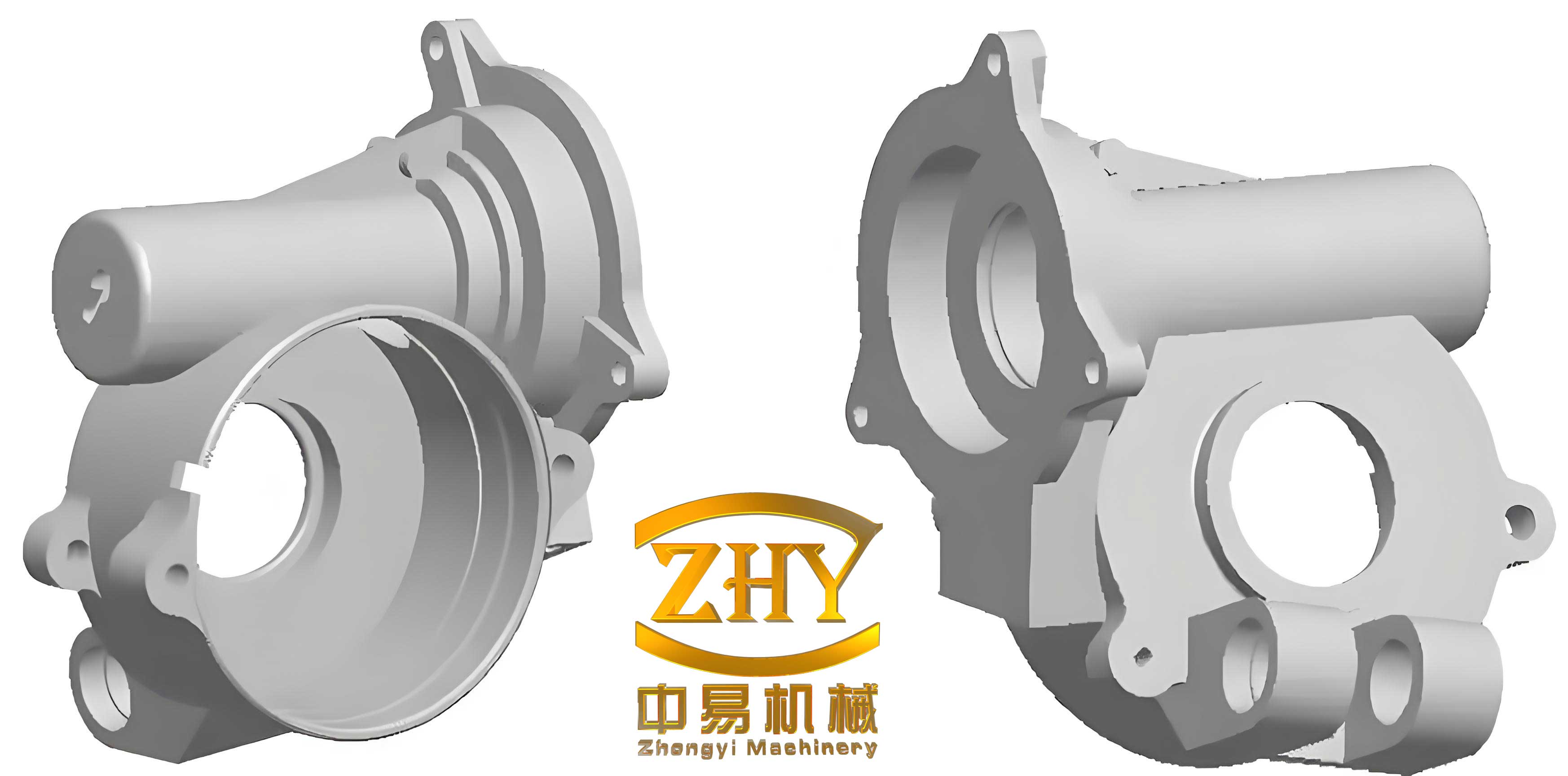
To tackle the complexities of shell castings, I adopted a dual-core design for the mold assembly. This approach simplifies mold-making and core placement, reducing the number of cores needed while ensuring accurate internal cavity formation. The cores are split into two parts: one forms the main internal cavity of the shell casting, and the other creates the hollow sections in the connecting arms. This design enhances mold stability and facilitates venting, which is crucial for preventing gas-related defects in shell castings. The gating system was configured as an open type to promote smooth metal flow and effective slag trapping, with a pouring time set around 22 seconds. Key process parameters are summarized in the table below, highlighting the conditions tailored for shell castings.
| Parameter | Value | Description |
|---|---|---|
| Material | QT500-7 | Ductile iron grade |
| Casting Weight | 80 kg | Total weight of the shell casting |
| Wall Thickness | 40 mm | Uniform main wall |
| Pouring Temperature | 1410 °C | Initial metal temperature |
| Mold Temperature | 30 °C | Green sand initial temperature |
| Pouring Time | 22 s | Approximate duration |
| Gravity Acceleration | 9.8 m/s² | Standard gravity casting |
Prior to actual production, I utilized MAGMA software for CAE simulation to predict and optimize the casting process for shell castings. This step is vital for reducing trial-and-error costs and enhancing development speed. The simulation involved setting up the 3D model in STL format, meshing it, and defining parameters such as thermal properties and boundary conditions. Through this, I could visualize the filling and solidification sequences, identify potential defects like shrinkage porosity and hot tears, and refine the design accordingly. The governing equations for fluid flow and heat transfer in casting simulations include the Navier-Stokes equations for momentum conservation and the energy equation for thermal analysis. For instance, the heat conduction during solidification can be expressed as:
$$ \frac{\partial T}{\partial t} = \alpha \nabla^2 T $$
where \( T \) is temperature, \( t \) is time, and \( \alpha \) is thermal diffusivity. This equation helps model the cooling behavior in shell castings. Additionally, the feeding efficiency of risers and chills is assessed using empirical formulas like:
$$ V_r = \beta \cdot V_c \cdot ( \rho_s / \rho_l ) $$
where \( V_r \) is riser volume, \( V_c \) is casting volume, \( \beta \) is a safety factor, and \( \rho_s \) and \( \rho_l \) are solid and liquid densities, respectively. These calculations guide the placement of risers and chills to ensure sound shell castings.
The filling simulation revealed a stable metal flow pattern, with the ingates allowing uniform entry into the mold cavity. As shown in the velocity contours, the liquid metal advanced simultaneously in both cavity sections without turbulence, minimizing air entrapment and oxide formation. This is critical for shell castings, as turbulent flow can lead to surface defects and inhomogeneities. The table below summarizes the filling characteristics observed in the simulation for shell castings.
| Stage | Flow Velocity (m/s) | Observation |
|---|---|---|
| Initial Pouring | 0.5-0.8 | Smooth entry, no splash |
| Mid-filling | 0.3-0.6 | Uniform rise, minimal vortices |
| Final Filling | 0.1-0.3 | Complete filling without backflow |
Solidification simulation provided insights into the thermal gradients and defect formation in shell castings. The results indicated that the flange areas were the last to solidify, confirming them as hot spots. By incorporating risers at the top flange and chills at the bottom flange, I optimized the thermal management to extend the feeding range and reduce shrinkage. The Niyama criterion, often used to predict shrinkage porosity, is given by:
$$ N_y = \frac{G}{\sqrt{T}} $$
where \( G \) is temperature gradient and \( T \) is cooling rate. Values below a threshold indicate prone regions for microporosity in shell castings. My simulation output showed that after optimization, the Niyama values exceeded critical levels in most areas, signifying reduced risk. The solidification time \( t_s \) can be estimated using Chvorinov’s rule:
$$ t_s = C \left( \frac{V}{A} \right)^n $$
where \( V \) is volume, \( A \) is surface area, and \( C \) and \( n \) are material constants. For this shell casting, the modulus \( V/A \) was calculated to ensure directional solidification toward the risers.
Through iterative simulation, I refined the process parameters to achieve a defect-free shell casting. The optimized design included a top riser with a volume ratio of 15% relative to the casting, and chills made of cast iron placed at strategic locations. The table below compares defect probabilities before and after optimization for shell castings, demonstrating the effectiveness of CAE-driven adjustments.
| Defect Type | Initial Probability | Optimized Probability | Improvement |
|---|---|---|---|
| Shrinkage Porosity | High (in flanges) | Low | ~80% reduction |
| Gas Porosity | Medium | Negligible | ~90% reduction |
| Hot Tears | Low | None | 100% elimination |
The benefits of CAE simulation for shell castings extend beyond defect control. It allows for predictive analysis of microstructure formation, such as graphite nodule count in ductile iron, which impacts mechanical properties. For QT500-7 shell castings, the simulation indicated a uniform distribution of spheroidal graphite, with nodule counts exceeding 100 nodules/mm², ensuring the desired tensile strength and elongation. The relationship between cooling rate and nodule count can be expressed as:
$$ N_n = k \cdot \dot{T}^{-m} $$
where \( N_n \) is nodule count, \( \dot{T} \) is cooling rate, and \( k \) and \( m \) are constants. This underscores how process parameters influence the quality of shell castings.
In conclusion, my work on this shell casting component highlights the integral role of CAE simulation in modern foundry practices. By combining dual-core mold design with MAGMA-based analysis, I successfully predicted and mitigated shrinkage defects, leading to a robust process for producing high-integrity shell castings. The optimized parameters, including riser and chill placement, resulted in a significant reduction in scrap rates, showcasing the value of simulation-driven optimization for shell castings. Future endeavors could explore advanced materials or multi-physics simulations to further enhance the performance of shell castings in demanding applications.
Overall, this case study reinforces that for complex shell castings, a systematic approach involving structural analysis, innovative process design, and thorough CAE validation is essential. As casting technologies evolve, the integration of simulation tools will continue to drive efficiency and quality in the production of shell castings, making them more reliable for critical industrial uses.