
In my extensive experience within the foundry industry, the production of large-scale shell castings, such as those for industrial fans, presents unique and formidable challenges. These shell castings are critical components, often characterized by their massive dimensions, complex geometries, and stringent quality requirements regarding dimensional accuracy, surface finish, and internal soundness. Traditional methods using standard flasks and pattern plates frequently fall short due to the sheer size of these components. Over the years, I have developed and refined a pit core-assembly molding technique specifically tailored for such large shell castings. This approach allows for the production of high-quality castings with relatively minimal investment in specialized tooling. The core philosophy revolves around meticulous control over every stage: from core and mold design to sand strength management, melting, and pouring. This article will detail the entire process, emphasizing key design principles, calculations, and quality control measures that ensure success. The term ‘shell castings’ will be a recurring theme, as the entire methodology is built around their specific demands.
The primary shell castings I have worked with are typically split into upper and lower halves, made from grades like HT250, with individual weights reaching up to 40 tonnes and envelope dimensions exceeding 6.9 meters in length. The wall thickness varies significantly, from relatively thin sections of 45 mm in the body to massive flanges of 150 mm. This variation necessitates a carefully engineered solidification sequence. Furthermore, specifications often require precise dimensional tolerances (e.g., CT10 for flow paths), a smooth surface roughness of Ra 50μm, and rigorous non-destructive testing like kerosene penetration for bearing housings and magnetic particle inspection for support lugs. The initial product analysis for any shell casting must thoroughly evaluate these factors to inform the subsequent工艺 design.
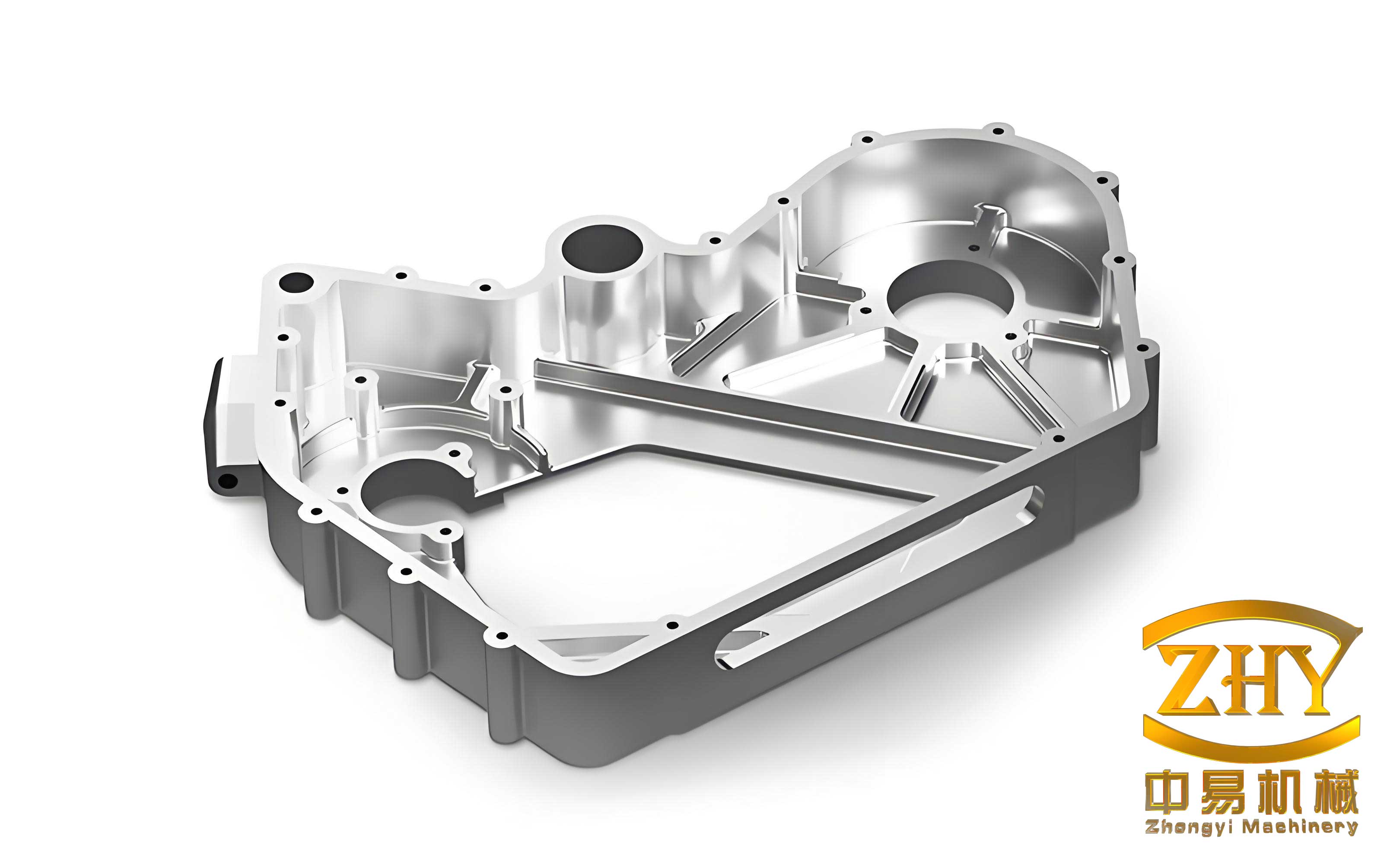
The fundamental process scheme for these large shell castings is the pit core-assembly method. The parting line is decisively set at the horizontal mid-plane of the casting. This orientation positions the important flow channel openings upward, which promotes denser metallurgical structure in critical internal surfaces and greatly simplifies the positioning and securing of the extensive core assemblies that form the internal cavity. A general linear shrinkage allowance of 0.8% is applied, with specific adjustments (e.g., 6.5%) for support boss areas. Machining allowances are typically set at 15 mm, and a core gap of 2 mm is standard to account for coating thickness and minor discrepancies. Instead of a conventional pattern plate, a dedicated core head or ‘bedding-in’ template is constructed. This template, leveled using a laser level, is used to form precise cavities in the pit floor with furan resin sand. Once cured, the template is removed, leaving behind accurate registrations for the core assemblies. The external mold is not a monolithic piece but is itself built from multiple large cores, referenced from a non-machined base surface. All these external cores are pre-assembled on the template, adjusted to drawing dimensions, marked with alignment lines, and then finally enclosed within a reinforcing steel frame or ‘cope’ filled with resin sand. Heavy weights are placed on top to counter metallostatic pressure during pouring.
The design of the cores is paramount for shell castings of this size. To manage complexity, weight, and deformation, the core system is strategically divided. For a typical fan casing, the internal cavity core is split horizontally. The lower section forms the primary flow path, while the upper section completes the geometry. The external mold is decomposed into numerous segments. For instance, the first layer might consist of cores defining the inlet diffuser and extended body, while the second layer defines the large inlet and outlet flanges and the central body. This modular approach makes handling feasible—individual core weights range from 20 kg to 150 kg. Core boxes, often constructed from reinforced timber, must be robust. They are strengthened with steel channels and secured with numerous bolts at intervals of 800-1000 mm along their length and height. Critical internal core boxes employ baseplates with alignment pins for accuracy. A standard practice is to build core boxes for the maximum casting length in a series, using interchangeable inserts or blocks to adjust for shorter variants. The verticality of core box frames is controlled within 0.3% error.
The bedding-in template, essentially a negative of all core prints, is a cornerstone of this method for shell castings. Its design parameters are critical: a negative draft of 10 mm, modular segments corresponding to different casting lengths (e.g., 132 mm increments), and a 2 mm gap between segments. Locating blocks ensure precise alignment during template assembly. Crucially, centerlines for inlet and outlet axes are marked on the template surface. After the template is used to form the sand cavities in the pit, these lines are extended onto the sand, providing the primary reference network for all subsequent core placement. This system replaces the need for a massive, single-piece pattern plate.
The gating and feeding system design for heavy-section shell castings requires careful calculation to ensure smooth filling and soundness. A bottom-side gating system is preferred for its calm filling characteristics, which minimizes turbulence, slag entrapment, and oxide formation. The effective pouring time is a key parameter. Based on established foundry principles and modifying factors for wall thickness, I use the following formula to determine the pouring time (t) for large castings using a stopper-runner system:
$$ t = f \left( \sqrt{G} + \frac{1}{5} \sqrt{\delta G} \right) \times \left( \frac{2}{3} \right)^{n-1} $$
Where:
$t$ is the effective pouring time in seconds,
$f$ is a material coefficient (taken as 1 for gray iron),
$G$ is the casting weight (excluding gates and risers) in kg,
$\delta$ is the predominant wall thickness of the casting in mm, and
$n$ is the number of gating system sections (or groups).
For a 40-tonne shell casting with a main wall thickness of 150 mm and a 4-gate system, the calculated pouring time falls within the range of 110-120 seconds. This time directly informs the choke area of the gating system. The system is designed to be initially choked and then open, promoting slag trapping in the early stage and steady flow thereafter. The cross-sectional area ratio for the system is typically set as: $\sum F_{\text{sprue}} : \sum F_{\text{choke}} : \sum F_{\text{runner}} : \sum F_{\text{ingate}} = 1.3 : 1 : 1.8 : 2$. For the example, the minimum choke area is approximately 127 cm², distributed across four gates.
Feeding these thick-section shell castings, particularly the large flanges, is achieved through a combination of risers and chills. Given the high mold strength from resin sand, a “mouth” or “duck-bill” type riser is employed. This design uses a restrictive riser neck to control the timing of feed metal transfer, accommodating both initial liquid contraction and later graphitic expansion in gray iron. The riser neck dimensions might be 100 mm x 60 mm x 50 mm, with a riser body of Ø150 mm x 375 mm. Multiple risers are placed on the thick flanges. Extensive use of external chills is made on the heavy vertical sections of the mid-plane parting face to promote directional solidification towards the risers. Chill plates, 80 mm thick, are placed with a 30 mm gap between them. Similarly, shaped chills are used at support lug locations to ensure soundness and prevent cracking.
The metallurgical control for such large shell castings is equally vital. Melting is conducted in medium-frequency induction furnaces. The charge consists of 30% steel scrap and 70% returns. Carbon, silicon, and manganese levels are adjusted using recarburizer, 75% ferrosilicon, and 65% ferromanganese. The target base composition before inoculation is: Carbon: 3.2-3.3%, Silicon: 1.7%, Manganese: 0.75%. A final inoculation is performed during tapping to achieve a total silicon content of $1.85\% \pm 0.05\%$, resulting in a carbon equivalent (CE) between 3.8% and 3.9%, calculated as:
$$ \text{CE} = \%C + \frac{1}{3}(\%Si + \%P) $$
Pouring is a coordinated operation. A central stopper-pour basin is used, fed by multiple ladles via runners. For instance, a 12-tonne ladle is poured into the basin first. Once the iron temperature reaches $1320^\circ\text{C} \pm 10^\circ\text{C}$, the stopper is opened to begin filling the mold. Subsequent ladles (e.g., 15-tonne and 15-tonne) feed through side channels to maintain a continuous flow without interruption, which is critical for the quality of such massive shell castings.
Quality control during core making and assembly is systematic and data-driven. For large cores, the selection of core reinforcement (core bars), number of lifting lugs, and handling times are standardized based on core weight to prevent deformation, breakage, and ensure safety. The following table summarizes the control parameters I have established through practice for cores used in large shell castings:
| Core Weight (t) | Sand Working Time (min) | Stripping Time (min) | Number of Core Bars | Core Bar Material | Number of Lifting Lugs | Lug Material |
|---|---|---|---|---|---|---|
| ≤ 0.5 | 8 – 10 | 30 – 40 | 2 – 4 | Round Steel | 2 | Round Steel |
| 0.5 – 1 | 10 – 15 | 30 – 40 | 4 – 6 | Round Steel | 3 | Round Steel |
| 1 – 2 | 12 – 18 | ≥ 60 | 4 – 6 | Round Steel | 4 | Round Steel |
| 2 – 3.5 | 15 – 20 | ≥ 120 | 4 – 6 | Round Steel, Cast Iron | 4 | Round Steel |
| 3.5 – 5 | 18 – 22 | ≥ 180 | 6 – 8 | Round Steel, Cast Iron | 4 | Round Steel |
| 5 – 10 | 20 – 28 | ≥ 240 | 6 – 8 | Ductile Iron Core Grid | 4 | Round Steel |
| 10 – 20 | 25 – 35 | ≥ 360 | 8 – 10 | Ductile Iron Core Grid | 4 | Round Steel |
Core box maintenance is also critical. Before production, each box must be verified against drawings for dimensional accuracy of all parts and alignment pins. The working surfaces are regularly coated with parting agent to ensure a smooth finish on the sand cores for the shell castings.
The core assembly operation demands precision. All cores are numbered according to the planned placement sequence. On the leveled pit bed, after the template is removed, a comprehensive network of reference lines is established. A central axis line is drawn, and parallel lines are marked at fixed offsets (e.g., 2 meters on either side) to serve as visual guides for coaxial alignment of the internal cavity cores. The external cores undergo a dry pre-assembly on the pit bed. Starting from a defined datum core, adjacent cores are positioned, their collective dimensions verified against the drawing, and mating surfaces are marked with alignment lines and smoothed. This pre-assembly is then carefully disassembled. During final molding, the internal cores are placed first, aligned to the reference lines. Then, the external cores are positioned precisely according to the marks made during pre-assembly, ensuring the final mold cavity for the shell casting is dimensionally accurate. Any minor steps at core joints are hand-blended to create a smooth transition.
The solidification dynamics of such thick-walled shell castings can be further analyzed. The solidification time ($t_s$) for a simple shape can be estimated using Chvorinov’s rule:
$$ t_s = K \left( \frac{V}{A} \right)^n $$
Where $V$ is volume, $A$ is surface area, $K$ is a mold constant, and $n$ is an exponent (typically ~2). For complex shell castings, this is applied zone-by-zone to design the chilling and risering. The required riser volume ($V_r$) can be related to the feeding demand of the casting section it supports, considering the volumetric shrinkage ($\varepsilon$) of the metal:
$$ V_r \geq \frac{V_c \cdot \varepsilon}{ \eta } $$
Where $V_c$ is the volume of the casting region fed, and $\eta$ is the riser efficiency. For the ductile iron used in some similar heavy castings, the expansion phase must also be factored in, but for gray iron shell castings, the restrictive riser neck helps manage this.
Another critical aspect is the calculation of the mold wall movement and the resulting dimensional stability of the final shell casting. The high ferrostatic pressure can lead to mold wall deflection, which is mitigated by the reinforced cope and the high strength of the cured resin sand. The pressure ($P$) at a depth ($h$) in the mold is given by:
$$ P = \rho g h $$
Where $\rho$ is the density of molten iron (~7000 kg/m³) and $g$ is gravity. For a shell casting 2 meters tall, the pressure at the bottom can approach 0.14 MPa, necessitating robust mold construction.
To summarize the key process parameters for different sizes of shell castings, I often refer to an expanded specification table:
| Process Parameter | Small Shell Castings (<10t) | Medium Shell Castings (10-25t) | Large Shell Castings (>25t) |
|---|---|---|---|
| Typical Shrinkage Allowance | 0.9 – 1.0% | 0.85 – 0.9% | 0.8 – 0.85% |
| Core Sand Type | Furan / Alkyd | Furan Resin | Furan Resin (High Strength) |
| Mold Sand Type | Green Sand / Furan | Furan Resin | Furan Resin |
| Gating System Type | Bottom / Side | Bottom-Side w/ Stopper | Bottom-Side w/ Stopper & Multiple Ladles |
| Pouring Temperature Range | 1340 – 1380°C | 1320 – 1360°C | 1300 – 1340°C |
| Riser Type | Conventional Top Riser | Neck-restricted Riser | ‘Duck-bill’ / Mouth Riser |
| Chill Usage | Selective | Extensive on thick sections | Comprehensive on mid-plane & lugs |
| Post-Casting Stress Relief | Natural Aging / Vibration | Vibration Stress Relief | Thermal Stress Relief / Vibration |
The success of this pit core-assembly method for shell castings is evident in several metrics. The casting yield (weight of sound casting vs. total metal poured) typically achieves 86% to 90%, which is excellent for such large components. However, the sand-to-metal ratio is relatively high, often around 4.5:1, due to the extensive core work and the pit molding itself. From a quality perspective, over the production of numerous shell castings using this method, defect rates have been very low. Occasional instances of sand inclusions or minor shifts have been encountered, but these are generally repairable by welding or surface processing, and all castings have met final customer specifications. The dimensional consistency of the shell castings, particularly the alignment of the flow paths and flange positions, has been consistently validated.
In conclusion, the design and implementation of a pit core-assembly molding process for large shell castings is a comprehensive engineering task. It requires a deep understanding of foundry principles, solid mechanics, and metallurgy. The key lies in deconstructing the complex geometry into manageable core segments, establishing an impeccable reference system via the bedding-in template, designing a controlled filling and feeding system based on calculated parameters, and enforcing rigorous quality control during core making and assembly. This approach democratizes the production of massive, high-integrity shell castings, making it feasible without prohibitively large pattern equipment. Future developments may involve further digitization of the process, using 3D scanning to verify core assemblies or simulation software to optimize gating and solidification even before the first mold is made. Nevertheless, the core principles outlined here remain foundational for the reliable manufacture of these critical industrial components. The repeated focus on the specific needs of shell castings throughout this process—from the initial analysis of their thick-thin wall transitions to the final quality checks on their pressure-containing surfaces—highlights how a tailored methodology is essential for success in heavy foundry work.