
In the field of casting production, particularly for energy and power systems, the manufacturing of heavy-section gray iron castings presents significant challenges. As a casting engineer with extensive experience, I have encountered numerous cases where thick-walled components, such as bearing housings, require meticulous process design to avoid defects like shrinkage cavities, cracks, and poor microstructure. This article delves into a detailed case study involving a high-strength, heavy-section gray iron bearing housing, highlighting the iterative process improvements that led to successful production. The focus is on addressing shrinkage defects through strategic modifications in pouring position, riser design, chilling, and compositional adjustments, all while leveraging simulation tools like MAGMA for validation. Throughout this discussion, the term ‘gray iron castings’ will be emphasized to underscore its relevance in industrial applications.
The bearing housing in question is a critical component for drainage and energy power systems, characterized by its substantial weight and varying wall thicknesses. These gray iron castings are designed with a nominal material grade of HT300, equivalent to Class 30 gray iron in ASTM standards, requiring high tensile strength and absence of defects such as porosity, cracks, sand inclusions, or shrinkage. The structural configuration includes a base face with a massive thickness of 250 mm, while other sections taper down to 30 mm at minimal points and 80 mm in curved regions. This disparity in wall thickness inherently leads to non-uniform cooling, high residual stresses, and difficulty in liquid feeding during solidification—common pitfalls in producing heavy-section gray iron castings.
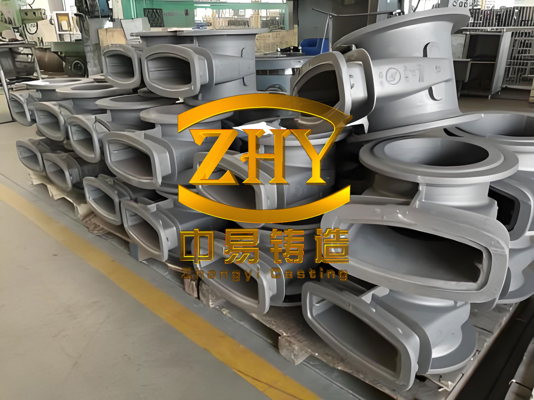
To understand the root causes of defects, it is essential to analyze the initial process. The original casting method employed resin sand manual molding, with the parting line set at the top of the thick base face. This placed the entire casting in the upper mold, positioning the critical machined surfaces (inner bore, bearing end face, and base face) at the bottom or sides. The gating system was designed as a closed type with area ratios: $$ F_{\text{sprue}} : F_{\text{runner}} : F_{\text{ingate}} = 1 : 1.8 : 0.85 $$, featuring simultaneous top and bottom filling through side gates. Chills were applied to the thick base face, and duck-bill risers were placed on the top surface to aid feeding. The molten iron composition, as controlled initially, is summarized in Table 1, with pouring temperatures ranging from 1320°C to 1340°C.
| Element | Carbon (C) | Silicon (Si) | Manganese (Mn) | Phosphorus (P) | Sulfur (S) | Copper (Cu) | Carbon Equivalent (CE) |
|---|---|---|---|---|---|---|---|
| Content (%) | 3.10 | 1.68 | 0.86 | 0.028 | 0.007 | 0.45 | 3.66 |
Despite these measures, production of six castings resulted in four rejects due to concentrated shrinkage cavities and cracks near the riser roots. This defect pattern indicated inadequate feeding during the late stages of solidification. For heavy-section gray iron castings, the solidification process is governed by principles of heat transfer and liquid metal flow. The solidification time can be estimated using Chvorinov’s rule: $$ t = B \left( \frac{V}{A} \right)^n $$ where \( t \) is solidification time, \( V \) is volume, \( A \) is surface area, \( B \) is a mold constant, and \( n \) is an exponent typically around 2 for sand molds. In this case, the thick base face, with a modulus \( M = V/A \) approximately 250 mm / 2 = 125 mm (simplified), solidified slowly, requiring prolonged liquid feeding. The original risers, being distant and poorly positioned, failed to provide sufficient feed metal, leading to shrinkage.
Further analysis revealed that the sprue’s proximity to the casting created a hot zone, delaying local solidification and exacerbating shrinkage risks. Additionally, the high pouring temperature contributed to increased liquid contraction, expressed as: $$ \Delta V_{\text{liquid}} = \beta \cdot V_0 \cdot \Delta T $$ where \( \beta \) is the volumetric shrinkage coefficient of gray iron (approximately 0.04% per °C), \( V_0 \) is initial volume, and \( \Delta T \) is temperature drop. For gray iron castings, the graphite expansion during eutectic solidification can partially offset shrinkage, but in heavy sections, this compensation is often insufficient if feeding paths are obstructed.
To address these issues, a comprehensive process redesign was undertaken. The key modifications included:
- Reorienting the casting: The parting line remained unchanged, but the thick base face was moved to the top of the mold, placing it in the upper section. This allowed for better control of feeding through risers and facilitated directional solidification from thin to thick sections.
- Revising the gating system: The sprue was relocated 200 mm away from the casting to reduce thermal influence. The gating ratio was adjusted to $$ F_{\text{sprue}} : F_{\text{runner}} : F_{\text{ingate}} = 1 : 1.5 : 0.85 $$, with ingates positioned at the bearing end face to ensure balanced filling.
- Enhancing chilling: Direct chills with thickness exceeding 120 mm were placed on the top thick face to accelerate cooling, refine microstructure, and reduce shrinkage tendency.
- Optimizing risers: Duck-bill risers were repositioned to avoid hot spots, and a pressing riser was added at the end opposite the sprue to provide feed metal without creating large thermal junctions.
- Adjusting process parameters: The pouring temperature was lowered to 1300°C–1320°C to minimize liquid contraction, feasible due to the thin sections filling first. The composition was modified to increase carbon equivalent and copper content, improving fluidity and feeding characteristics, as shown in Table 2.
| Element | Carbon (C) | Silicon (Si) | Manganese (Mn) | Phosphorus (P) | Sulfur (S) | Copper (Cu) | Carbon Equivalent (CE) |
|---|---|---|---|---|---|---|---|
| Content (%) | 3.25 | 1.75 | 0.85 | 0.025 | 0.006 | 0.58 | 3.85 |
The carbon equivalent (CE) is calculated as: $$ \text{CE} = \text{C} + \frac{\text{Si} + \text{P}}{3} $$ For gray iron castings, a higher CE promotes graphite formation, which aids in compensating shrinkage through expansion. The increase from 3.66% to 3.85% enhanced this effect, while copper addition strengthened the matrix without impeding graphite precipitation.
To validate these changes, MAGMA simulation software was employed. Initial simulations of the revised design still indicated shrinkage risks at the riser roots due to large contact thermal junctions. This led to further optimization: the central duck-bill risers were eliminated, and a pressing riser was incorporated at the far end. The simulation outputs, analyzed for temperature gradients and solidification sequences, confirmed that the new layout ensured adequate feeding. The feeding distance in gray iron castings can be approximated by: $$ L_f = \frac{T_{\text{pour}} – T_{\text{solidus}}}{G} $$ where \( L_f \) is feeding distance, \( T_{\text{pour}} \) is pouring temperature, \( T_{\text{solidus}} \) is solidus temperature, and \( G \) is temperature gradient. By placing chills and risers strategically, the gradient was steepened, reducing \( L_f \) and minimizing isolated liquid pockets.
The final process design, as simulated, showed no shrinkage defects. Production trials were conducted, with two initial castings achieving full integrity. Subsequently, a batch of 30 gray iron castings was manufactured without a single reject. Machining revealed sound surfaces with no subsurface defects, and mechanical testing demonstrated compliance with specifications. Table 3 summarizes the metallurgical and mechanical properties of the optimized bearing housings, underscoring the success of the improvements.
| Property | Material Grade | Tensile Strength (MPa) | Hardness (HB) | Graphite Morphology | Graphite Length (Grade) | Pearlite Content (%) |
|---|---|---|---|---|---|---|
| Value | HT300 | 320 | 180 | Type A | 5 | 85 |
The graphite morphology, classified as Type A per ASTM A247, indicates a uniform distribution, which is crucial for the performance of gray iron castings. The pearlite content of 85% ensures high strength and wear resistance. These results highlight how process refinements can yield superior gray iron castings even in challenging heavy-section applications.
From this experience, several key lessons emerge for producing heavy-section gray iron castings. First, the pouring position must prioritize feeding dynamics over mere convenience. By placing thick sections at the top, risers can effectively supply liquid metal during solidification. Second, riser design should avoid direct contact with major hot spots; pressing risers or side risers often perform better than top risers in thick regions. Third, chills are indispensable for controlling cooling rates in massive sections, preventing coarse graphite and shrinkage. The effectiveness of chills can be quantified by the chill factor: $$ C_f = \frac{k_{\text{chill}} \cdot A_{\text{chill}}}{k_{\text{mold}} \cdot A_{\text{mold}}} $$ where \( k \) denotes thermal conductivity and \( A \) area. A high \( C_f \) accelerates heat extraction, refining the microstructure of gray iron castings.
Furthermore, compositional adjustments play a pivotal role. Increasing carbon equivalent enhances graphitization, which offsets shrinkage through expansion pressures described by: $$ P_{\text{graphite}} = \frac{E_{\text{iron}} \cdot \Delta V_{\text{graphite}}}{V_{\text{total}}} $$ where \( E_{\text{iron}} \) is Young’s modulus, and \( \Delta V_{\text{graphite}} \) is the volume change due to graphite precipitation. For gray iron castings, this pressure can reach several MPa, aiding in feeding if properly harnessed. Additionally, alloying elements like copper improve strength without compromising castability.
Simulation tools like MAGMA are invaluable for iterative optimization. They allow visualization of thermal fields, solidification fronts, and defect prediction, reducing costly trial runs. In this case, simulations guided the elimination of problematic risers and confirmed the adequacy of feeding distances. For future projects, such software can be integrated with empirical data to develop robust processes for diverse gray iron castings.
In conclusion, the production of heavy-section gray iron castings demands a holistic approach combining sound metallurgical principles, strategic process design, and modern simulation techniques. By reorienting the casting, optimizing risers and chills, and fine-tuning composition, shrinkage defects were eliminated in the bearing housing application. This success underscores the importance of adaptive engineering in foundry practices. As the industry advances, continued focus on such methodologies will enhance the reliability and quality of gray iron castings for critical applications in energy, transportation, and infrastructure sectors. The journey from defect analysis to solution implementation reaffirms that even the most challenging gray iron castings can be produced flawlessly with systematic optimization and deep process understanding.