
In my extensive involvement with low-pressure die casting (LPDC) processes for automotive components, particularly engine cylinder heads, I have consistently encountered various casting defects that challenge production efficiency and product quality. The inherent complexity of cylinder head geometries, necessitating the use of sand cores for internal passages, amplifies the risk of defects such as oxidation inclusions, porosity, shrinkage, and cracks. This article delves into a comprehensive analysis of these casting defects, drawing from practical experiences and theoretical insights. I will elucidate the root causes, diagnostic features, and effective mitigation strategies, employing tables and mathematical formulations to encapsulate key concepts. Throughout this discussion, the term ‘casting defect’ will be recurrently emphasized to underscore its criticality in manufacturing. The goal is to provide a detailed resource that aids in minimizing these defects, thereby enhancing the integrity and performance of cast aluminum alloy components.
Low-pressure die casting is a favored method for producing high-integrity aluminum alloy castings like cylinder heads due to its controlled filling and solidification characteristics. The process involves pressurizing a sealed furnace containing molten aluminum, forcing the metal upward through a riser tube into a mold cavity. After filling, pressure is maintained to feed shrinkage during solidification. Despite its advantages, the process is susceptible to several casting defects if parameters are not meticulously optimized. The aluminum alloy commonly used, akin to the AC4B specification, has a composition that influences fluidity, shrinkage, and susceptibility to defects. A typical composition range is summarized in Table 1.
| Cu | Si | Mg | Zn | Fe | Mn | Ni | Ti | Ca | Al |
|---|---|---|---|---|---|---|---|---|---|
| 2.5–3.5 | 8.5–9.5 | 0.15–0.25 | ≤0.3 | ≤0.5 | ≤0.3 | ≤0.1 | ≤0.1 | ≤0.002 | Bal. |
The production sequence typically includes sand core making, aluminum melting and refining, low-pressure casting, heat treatment, and inspection. Each stage introduces potential variables that can lead to casting defects. For instance, improper core sand selection can increase gas evolution, while inadequate molten metal treatment can foster inclusions. To contextualize the geometry under discussion, consider the following image of an engine cylinder block, which shares structural similarities with cylinder heads in terms of complex passages and thickness variations:
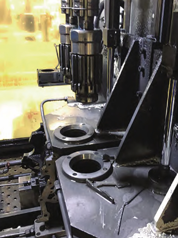
This complexity necessitates a deep understanding of defect mechanisms. In the following sections, I will systematically address each major casting defect category, starting with oxidation inclusions.
Oxidation Inclusions: A Persistent Casting Defect
Oxidation inclusions, often manifested as non-metallic particles embedded in the casting, are a prevalent casting defect in LPDC. They predominantly appear on upper surfaces and in poorly vented mold corners. In cylinder heads, these defects concentrate on surfaces such as the spark plug face and camshaft chamber. The fracture surface exhibits grayish-white or yellowish hues, and detection methods include X-ray radiography, machining, or chemical treatments like acid washing.
The primary causes of this casting defect are multifaceted. First, contaminated charge materials, especially excessive use of returns (often limited to ≤15% to avoid impurity accumulation), introduce oxides. Second, inadequate removal of oxide dross during molten metal processing leaves inclusions suspended. Third, insufficient holding time after degassing and refining prevents buoyant separation of inclusions. To quantify the effect of returns, consider the impurity accumulation model: if the inclusion concentration in returns is \( C_r \) and in fresh metal is \( C_f \), the overall concentration \( C \) after mixing a fraction \( f \) of returns is:
$$ C = f C_r + (1 – f) C_f $$
For \( f > 0.15 \), \( C \) often exceeds permissible limits, exacerbating the casting defect. Prevention strategies are summarized in Table 2.
| Causes of Casting Defect | Prevention Measures |
|---|---|
| High percentage of returns (>15%) | Limit returns to ≤15%; use clean, dry charge materials. |
| Ineffective slag removal during melting | Employ fluxing agents and degassing systems (e.g., GBF units with nitrogen purging). |
| Insufficient holding time post-refining | Allow 5–10 minutes of settling before transfer to holding furnace. |
| Oxide buildup in holding furnace | Perform regular furnace cleaning and use in-situ degassing with lances. |
| Lack of filtration during casting | Place fine-mesh ceramic filters at gate inlets to trap inclusions. |
Implementing these measures significantly reduces the incidence of this casting defect. For example, using filters with mesh sizes below 50 ppi can capture particles larger than 0.5 mm, as per the filtration efficiency equation:
$$ \eta = 1 – \exp\left(-\frac{\alpha L}{d_p}\right) $$
where \( \eta \) is efficiency, \( \alpha \) is a constant, \( L \) is filter thickness, and \( d_p \) is particle diameter. This underscores the importance of integrated approaches to mitigate inclusion-related casting defects.
Porosity: Gas-Related Casting Defects
Porosity, another critical casting defect, manifests as spherical or elliptical voids with smooth, oxidized surfaces. These can be superficial or internal, detectable via X-ray or ultrasonic inspection. In cylinder heads, porosity often coexists with oxidation inclusions, particularly in upper regions near cores. The formation of this casting defect is driven by gas entrapment during filling or solidification, primarily from core sand decomposition or air entrainment.
The solubility of hydrogen in aluminum alloys plays a key role. Hydrogen solubility decreases sharply during solidification, leading to pore nucleation. The equilibrium hydrogen concentration \( C_H \) follows Sieverts’ law:
$$ C_H = K_H \sqrt{P_{H_2}} $$
where \( K_H \) is the solubility constant and \( P_{H_2} \) is the partial pressure of hydrogen. Upon cooling, supersaturation occurs, and pores form if the critical pressure \( P_c \) for nucleation is exceeded:
$$ P_c = \frac{2\gamma}{r} + \rho g h $$
Here, \( \gamma \) is surface tension, \( r \) is pore radius, \( \rho \) is density, \( g \) is gravity, and \( h \) is metallostatic head. Factors exacerbating this casting defect include high core sand gas evolution, poor mold venting, improper coating application, and suboptimal pouring parameters. Core sands with low gas evolution (e.g., coated sands like YKS series) are essential. The gas evolution rate \( \dot{G} \) can be modeled as:
$$ \dot{G} = A \exp\left(-\frac{E}{RT}\right) $$
where \( A \) is a pre-exponential factor, \( E \) is activation energy, \( R \) is gas constant, and \( T \) is temperature. Using low-\( \dot{G} \) sands reduces gas pressure buildup. Additionally, optimizing LPDC parameters—such as extending fill times to allow gas escape—is crucial. Table 3 outlines common causes and remedies for porosity as a casting defect.
| Causes of Casting Defect | Prevention Measures |
|---|---|
| High gas content in charge materials | Use degassed aluminum; avoid humid or contaminated scrap. |
| Excessive core sand gas evolution | Select low-gas sands (e.g., ≤10 mL/g at 850°C). |
| Inadequate mold venting | Add vent pins and vents at high points; ensure seal integrity. |
| Irregular coating application | Apply uniform coatings to regulate heat transfer and release gases. |
| High pouring temperature/speed | Lower pouring temperature to ~700°C; slow fill rate (e.g., 25–30 s). |
By addressing these factors, the occurrence of porosity casting defects can be markedly diminished, enhancing the pressure tightness of cylinder heads.
Shrinkage Porosity: A Solidification-Based Casting Defect
Shrinkage porosity, often termed microshrinkage or dispersed shrinkage, is a casting defect resulting from inadequate feeding during solidification. It typically occurs near gates, thick-thin transitions, and large thin sections. In cylinder heads, the combustion chamber area, adjacent to gates, is prone to this casting defect. Macroscopically, it appears as cloudy or网状 patterns on X-rays, with fractures showing grayish tones after heat treatment.
This casting defect arises from the volumetric contraction of aluminum alloys during solidification. The solidification shrinkage \( \beta \) is given by:
$$ \beta = \frac{\rho_l – \rho_s}{\rho_l} $$
where \( \rho_l \) and \( \rho_s \) are liquid and solid densities, respectively. For typical Al-Si alloys, \( \beta \approx 4–6\% \). If feeding is insufficient, microporosity forms. The Niyama criterion is often used to predict shrinkage casting defects:
$$ G / \sqrt{\dot{T}} \leq C $$
where \( G \) is temperature gradient, \( \dot{T} \) is cooling rate, and \( C \) is a constant. Low \( G \) and high \( \dot{T} \) promote shrinkage. In LPDC, factors like excessive pouring temperature, rapid cooling, or poor gating design can exacerbate this. To prevent this casting defect, directional solidification toward feeders must be ensured. Practical measures include optimizing process parameters: pressure during intensification should be 0.345–0.350 MPa, with hold times of 280–300 s to feed shrinkage. Additionally, controlling mold temperature gradients via cooling channels is vital. The heat transfer equation for mold cooling is:
$$ q = h (T_m – T_c) $$
where \( q \) is heat flux, \( h \) is heat transfer coefficient, \( T_m \) is mold temperature, and \( T_c \) is coolant temperature. Balanced cooling avoids hot spots that lead to shrinkage casting defects. Table 4 summarizes key aspects.
| Causes of Casting Defect | Prevention Measures |
|---|---|
| High pouring temperature (>710°C) | Reduce to ~700°C to decrease shrinkage volume. |
| Inadequate feeding pressure/time | Optimize pressure profile: slow ramp-up, prolonged hold. |
| Non-uniform mold cooling | Design cooling lines to promote gradient; repair leaks. |
| Poor gating design | Use chills or thermal modulators at hot spots. |
| Alloy composition variations | Maintain strict compositional control, especially Si/Mg ratio. |
Implementing these strategies effectively curtails shrinkage casting defects, improving the mechanical properties of castings.
Cracking: A Severe Casting Defect
Cracking, whether hot tearing during solidification or cold cracking during handling, is a detrimental casting defect in cylinder heads. Hot tears are intergranular and often associated with segregation, occurring in complex shapes with high contraction stress. In cylinder heads, the front face, with abrupt thickness changes, is susceptible. Cold cracks are transgranular, typically from rapid cooling or residual stresses post-heat treatment.
The thermal stress \( \sigma \) driving this casting defect can be approximated by:
$$ \sigma = E \alpha \Delta T $$
where \( E \) is Young’s modulus, \( \alpha \) is thermal expansion coefficient, and \( \Delta T \) is temperature difference. During solidification, the strain rate \( \dot{\epsilon} \) must remain below a critical value to avoid hot tearing. The Rappaz-Drezet-Gremaud criterion relates cracking susceptibility to coherency temperature range and strain accumulation. Factors like sharp corners, low sand core yield, local mold overheating, and premature ejection promote this casting defect. For instance, sand core yield stress should be minimized to allow contraction; adding wood flour to core sand improves collapsibility. The core yield stress \( \sigma_y \) as a function of temperature can be modeled:
$$ \sigma_y = \sigma_0 \exp\left(-\frac{T}{T_0}\right) $$
where \( \sigma_0 \) and \( T_0 \) are constants. Lower \( \sigma_y \) reduces restraint. Additionally, controlling cooling rates during T6 heat treatment (solutionizing and quenching) is crucial to avoid quench cracks. The quenching severity \( H \) affects residual stresses:
$$ H = \frac{h}{k} $$
with \( h \) as heat transfer coefficient and \( k \) as thermal conductivity. Using polymer quenchants can moderate \( H \). Table 5 encapsulates the causes and preventions for cracking casting defects.
| Causes of Casting Defect | Prevention Measures |
|---|---|
| Sharp corners and thickness transitions | Design radii >3 mm; gradual thickness changes. |
| High sand core restraint | Use collapsible cores with additives (e.g., 1–2% wood flour). |
| Localized mold overheating | Adjust heater flames to balance mold temperatures. |
| High pouring temperature | Lower to ~700°C to reduce thermal stress. |
| Early ejection from mold | Extend mold open time to allow stress relief. |
| Rapid quenching after solutionizing | Employ controlled quenching media (e.g., air or oil). |
| Violent knockout operations | Reduce vibratory knockout intensity; extend cycle time. |
By addressing these factors, cracking casting defects can be substantially mitigated, ensuring structural integrity.
Integrated Defect Prevention Framework
Beyond individual defects, a holistic approach is vital for minimizing casting defects in LPDC. This involves synergizing process control, material science, and simulation tools. Key elements include statistical process control (SPC) to monitor variables like molten metal temperature, pressure curves, and coating thickness. Design of experiments (DoE) can optimize parameters; for instance, response surface methodology can model defect occurrence as a function of pressure \( P \), temperature \( T \), and time \( t \):
$$ \text{Defect Index} = \beta_0 + \beta_1 P + \beta_2 T + \beta_3 t + \beta_{12} P T + \cdots $$
where \( \beta_i \) are coefficients. Additionally, computational fluid dynamics (CFD) and finite element analysis (FEA) simulate filling and solidification, predicting defect-prone zones. The continuity and momentum equations for molten flow are:
$$ \nabla \cdot \mathbf{u} = 0 $$
$$ \rho \left( \frac{\partial \mathbf{u}}{\partial t} + \mathbf{u} \cdot \nabla \mathbf{u} \right) = -\nabla p + \mu \nabla^2 \mathbf{u} + \rho \mathbf{g} $$
where \( \mathbf{u} \) is velocity, \( p \) is pressure, \( \mu \) is viscosity, and \( \mathbf{g} \) is gravity. Simulations help redesign gating and cooling systems to avoid casting defects. Moreover, advanced inspection techniques like real-time X-ray tomography aid in early defect detection. A comprehensive quality loop, from raw material certification to final audit, is essential. Table 6 outlines an integrated strategy.
| Aspect | Specific Actions | Impact on Casting Defect Reduction |
|---|---|---|
| Material Control | Use high-purity alloys; monitor returns percentage; implement hydrogen analysis. | Reduces inclusions and porosity casting defects. |
| Process Optimization | DoE-based parameter setting; closed-loop pressure control; uniform coating. | Minimizes shrinkage and gas-related casting defects. |
| Mold/Core Design | Simulation-driven design; adequate vents; collapsible cores; conformal cooling. | Prevents cracking and improves feeding. |
| Heat Treatment | Controlled quenching; stress relieving cycles; temperature uniformity surveys. | Mitigates cracking casting defects post-casting. |
| Inspection & Feedback | Automated X-ray/ultrasonic inspection; SPC charts; root cause analysis. | Enables rapid correction of casting defect trends. |
Implementing such a framework has proven effective in reducing overall casting defect rates by over 50% in many operations, underscoring the value of a systematic approach.
Conclusion
In conclusion, casting defects in low-pressure die casting of engine cylinder heads are multifaceted challenges that demand rigorous analysis and proactive measures. Through my experience, I have detailed how oxidation inclusions, porosity, shrinkage, and cracks manifest, their root causes, and practical prevention strategies. Employing tables and mathematical models helps encapsulate these complexities. Each casting defect requires tailored solutions—from material purity and process control to advanced simulation—but an integrated perspective is paramount. By continuously refining these aspects, manufacturers can achieve higher yield and reliability, turning the battle against casting defects into a sustainable competitive advantage. The journey to defect-free castings is iterative, but with diligent application of these principles, significant improvements are attainable, ensuring that casting defects become a manageable facet of production rather than a pervasive issue.