
In my extensive experience in the power generation industry, I have encountered numerous instances where casting defects pose significant challenges to the integrity and operation of critical equipment. One particularly notable case involved the main stop valve seat of a steam turbine, where casting defects were discovered during routine operation, leading to steam leakage. This article details my firsthand account of the investigation, analysis, and repair process using arc cold welding techniques, emphasizing the critical role of controlling parameters to ensure structural reliability. Throughout this discussion, I will repeatedly highlight the term casting defects to underscore their prevalence and impact in industrial applications.
The initial discovery was made during operational monitoring when steam leakage was observed from the valve seat neck. Upon shutdown and inspection, it became evident that the issue stemmed from internal casting defects, which are often inherent in the manufacturing process due to factors like improper solidification, gas entrapment, or inclusion formation. These casting defects can manifest as porosity, shrinkage cavities, sand inclusions, or slag entrapments, compromising component performance under high-temperature and high-pressure conditions. In this case, the defect was not merely a simple pinhole but a complex network of interconnected imperfections, including sand inclusions, slag, and shrinkage voids, forming a elongated cavity.
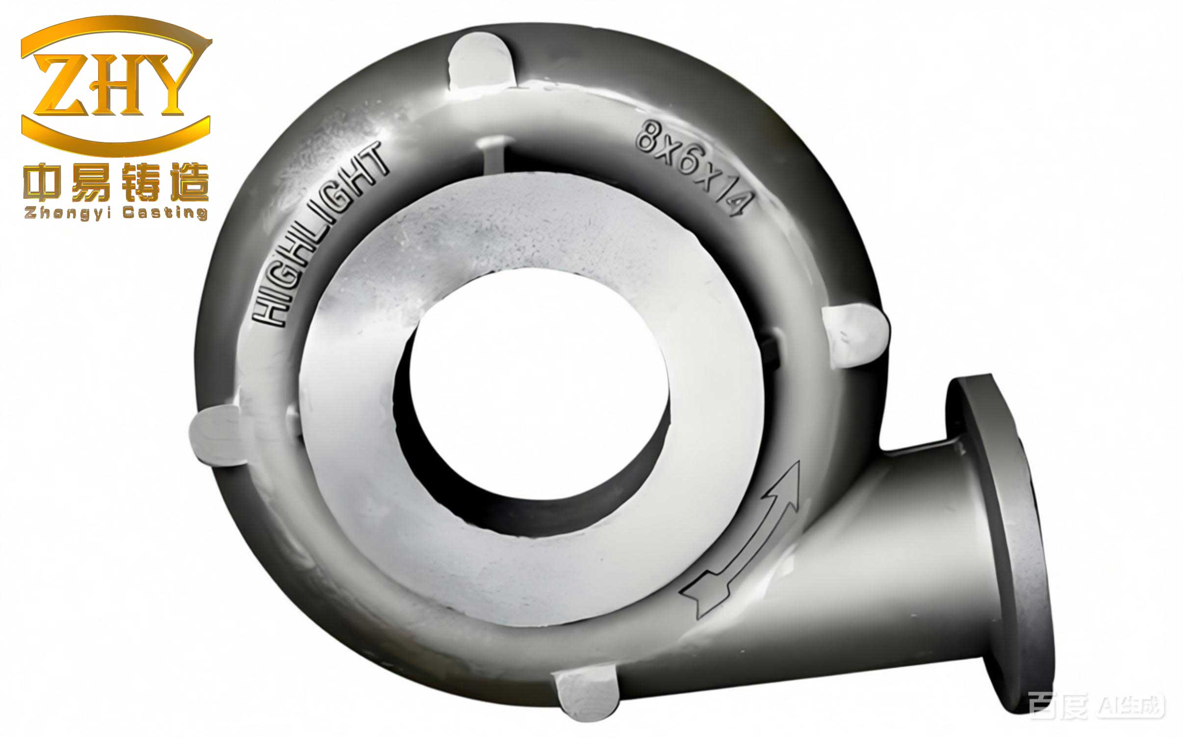
Upon careful excavation, the defect dimensions were measured: approximately 150 mm in length, 30 mm in width, and 35 mm in depth, with a small hole of about 5 mm diameter at the base penetrating the inner wall, leaving a residual wall thickness of only 5 mm. This configuration posed a severe risk, as casting defects of this magnitude can lead to catastrophic failures under cyclic thermal and mechanical loads. The valve seat material was identified as a pearlitic heat-resistant steel, which is known for its poor weldability due to high carbon equivalent and susceptibility to hardened microstructures like martensite, increasing the likelihood of cracking during welding.
The repair requirements were stringent, given the operating environment. The valve operates at elevated temperatures and pressures, and the turbine undergoes frequent start-stop cycles and load variations, inducing significant fatigue stresses. Therefore, the weld repair needed to ensure not only defect-free microstructure but also high-temperature creep strength, adequate ductility, and thermal stability. Additionally, since the valve body had been precision-machined, deformation control was paramount; the total deflection on the mating surface post-weld had to remain below 0.05 mm. The inherent rigidity of the valve body meant that residual stresses from welding could be substantial, and if not managed, they could superimpose with operational stresses, leading to stress concentration and reduced service life. Hence, controlling heat input and minimizing welding residual stresses were critical objectives.
To address these challenges, I opted for an arc cold welding process using austenitic stainless steel electrodes. This approach leverages the high ductility and crack resistance of austenitic deposits to mitigate the brittleness of the base metal. The repair was divided into two main phases: isolation layer welding and filler layer welding, each with specific parameters to control dilution and thermal effects.
First, let’s discuss the isolation layer welding. After thoroughly cleaning the defect cavity, I positioned it horizontally and preheated the surrounding area within a 150 mm diameter to 150°C using an oxy-acetylene flame. This mild preheat helps reduce thermal gradients and minimizes the risk of cold cracking. For the isolation layer, I used an E309 type electrode (similar to AISI 309), with a diameter of 3.2 mm and a welding current of 90–110 A. The key here was to maintain a low heat input to control the dilution ratio, which is the proportion of base metal melted into the weld metal. A high dilution can introduce excessive carbon and alloying elements from the base metal, compromising the austenitic structure’s properties. The welding technique involved rapid straight-line deposition without transverse oscillation, with a bead spacing of 2–3 mm (approximately one-third to half the bead width). I continuously welded three layers, pausing when the interpass temperature reached about 150°C to allow cooling. After each layer, when the weld was cool enough to touch, I performed peening—moderate hammering—to relieve residual stresses. This process was repeated until a uniform isolation layer covered the entire defect interface, effectively shielding the base metal from subsequent welding effects. Any cracks detected during inspection were ground out and rewelded, as the isolation layer is foundational to preventing defect propagation.
Next, the filler layer welding focused on building up the cavity with controlled temperature management. Here, dilution control was less critical, so I slightly increased the current to 100–120 A to enhance deposition rate, but still maintained an interpass temperature below 150°C to avoid excessive heat buildup. Each layer was deposited with similar rapid techniques, and peening was applied after cooling to touch. In total, 6 layers were required to fill the defect, completing the repair over approximately 48 hours. Post-weld inspection revealed no cracks, and installation confirmed no significant deformation, with the valve returning to service successfully.
To generalize this process, I have developed several formulas and tables to summarize the critical parameters. For instance, the heat input per unit length (\( Q \)) in welding can be calculated using the formula:
$$ Q = \frac{60 \times V \times I}{1000 \times v} $$
where \( V \) is the arc voltage (typically 20–25 V for manual arc welding), \( I \) is the welding current in amperes, and \( v \) is the travel speed in mm/min. In my repair, I kept \( Q \) below 1.5 kJ/mm to minimize thermal distortion and residual stresses. Another key aspect is the cooling rate, which influences microstructure formation. For pearlitic steels, the cooling time from 800°C to 500°C (\( t_{8/5} \)) should be controlled to avoid martensite; it can be estimated using empirical equations like:
$$ t_{8/5} = k \times \left( \frac{Q}{T_0 – T_i} \right)^2 $$
where \( k \) is a material constant, \( T_0 \) is the preheat temperature, and \( T_i \) is the interpass temperature. By maintaining \( T_0 \) at 150°C and \( T_i \) below 150°C, I ensured a slow enough cooling rate to prevent excessive hardening.
Below is a table summarizing the welding parameters used in the repair process, highlighting how each parameter addresses the challenges posed by casting defects:
| Welding Phase | Electrode Type | Current (A) | Voltage (V) | Travel Speed (mm/min) | Heat Input (kJ/mm) | Key Objective |
|---|---|---|---|---|---|---|
| Isolation Layer | E309 (Austenitic) | 90–110 | 22 | 120 | 0.99–1.21 | Minimize dilution, prevent cracking |
| Filler Layer | E309 (Austenitic) | 100–120 | 23 | 150 | 0.92–1.10 | Build-up with stress relief |
Furthermore, the types of casting defects encountered in such components can be categorized based on their origin and morphology. The table below provides a classification, which is essential for selecting appropriate repair strategies:
| Defect Type | Typical Causes | Impact on Weldability | Repair Approach |
|---|---|---|---|
| Shrinkage Cavities | Inadequate feeding during solidification | High stress concentration, prone to hot tearing | Pre-weld excavation and buttering |
| Sand Inclusions | Mold erosion or core failure | Acts as notch, reduces fatigue strength | Thorough cleaning and isolation layers |
| Gas Porosity | Gas entrapment during pouring | Can cause porosity in weld metal | Low-hydrogen processes and preheat |
| Slag Entrapments | Improper slag removal | Leads to lack of fusion | Grinding and back-gouging |
In addition to these practical measures, I often rely on metallurgical principles to guide repairs. For example, the Schaeffler diagram can predict the microstructure of weld metal based on composition, helping select electrodes that avoid brittle phases. The diagram uses chromium equivalent (\( Cr_{eq} \)) and nickel equivalent (\( Ni_{eq} \)), calculated as:
$$ Cr_{eq} = %Cr + %Mo + 1.5 \times %Si + 0.5 \times %Nb $$
$$ Ni_{eq} = %Ni + 30 \times %C + 0.5 \times %Mn $$
For the E309 electrode, with typical composition of 23% Cr and 12% Ni, the weld metal falls in the austenitic region, ensuring good toughness. This is crucial when repairing casting defects in hardenable steels, as it prevents the formation of martensite that could lead to cold cracking.
Residual stress management is another critical aspect. The magnitude of residual stress (\( \sigma_{res} \)) can be approximated using formulas from elasticity theory, such as:
$$ \sigma_{res} = E \times \alpha \times \Delta T \times f(Q, \text{constraint}) $$
where \( E \) is Young’s modulus, \( \alpha \) is the coefficient of thermal expansion, and \( \Delta T \) is the temperature change. By controlling \( Q \) through low heat input and using peening, I effectively reduced \( \sigma_{res} \) to acceptable levels. Peening introduces compressive stresses on the weld surface, counteracting tensile stresses from shrinkage, as described by the equation:
$$ \sigma_{comp} = k_p \times F \times A^{-1} $$
where \( k_p \) is a peening constant, \( F \) is the hammer force, and \( A \) is the area. In practice, I used moderate manual peening after each layer, ensuring uniform deformation without over-working the metal.
The success of this repair highlights the importance of a systematic approach to addressing casting defects. From my perspective, the key lessons include: thorough defect characterization, selection of compatible filler materials, strict control of thermal cycles, and post-weld stress relief. These principles are not limited to steam turbine valves but apply broadly to any component suffering from casting defects, such as pump casings, gearboxes, or structural frames.
To further elaborate, let’s consider the economic and safety implications. Unrepaired casting defects can lead to unscheduled downtime, costly replacements, or even accidents. In this case, the repair cost was a fraction of a new valve seat, and the extended service life demonstrated the efficacy of arc cold welding. I also recommend non-destructive testing (NDT) methods like ultrasonic testing or dye penetrant inspection before and after welding to verify defect removal and weld integrity. The table below compares common NDT techniques for detecting casting defects:
| NDT Method | Principle | Sensitivity to Casting Defects | Applicability in Repair |
|---|---|---|---|
| Ultrasonic Testing | Sound wave reflection | High for internal defects | Ideal for pre- and post-weld inspection |
| Dye Penetrant | Capillary action of dye | Surface-breaking defects only | Useful for crack detection in weld |
| Radiography | X-ray or gamma ray absorption | Excellent for volumetric defects | Costly but thorough for complex shapes |
| Magnetic Particle | Magnetic flux leakage | Ferromagnetic materials only | Limited for austenitic welds |
In conclusion, my experience with repairing casting defects in the steam turbine valve seat underscores the viability of arc cold welding as a reliable method. By adhering to precise parameters and incorporating stress-relief techniques, I achieved a repair that met all operational demands. This approach can be adapted to various industries where casting defects are a concern, from marine propellers to heavy machinery. As I continue to work in this field, I emphasize the need for continuous learning and adaptation, as each defect presents unique challenges. The integration of theoretical models, practical skills, and advanced materials is essential for overcoming the persistent issue of casting defects in engineered components.
Finally, I encourage fellow engineers to document and share their experiences with casting defects repairs, as collective knowledge enhances our ability to maintain infrastructure safely and efficiently. Whether through formal publications or industry forums, such exchanges contribute to improved standards and innovations in welding technology, ultimately reducing the incidence and impact of casting defects worldwide.