
In my extensive experience within the foundry industry, I have consistently observed that valves serve as critical control devices in pressure pipeline systems, responsible for regulating flow, direction, pressure, and ensuring operational safety across sectors like petrochemicals, power plants, and engineering pipelines. The demanding service conditions, particularly in石化 applications where corrosive media are prevalent, impose stringent quality requirements on valve castings. High-pound class valve bodies, characterized by large dimensions and thick sections, present significant challenges in casting process design, often leading to pervasive casting defects that compromise integrity. This article delves into a detailed analysis of such casting defects encountered in a high-pound class valve body production, employing simulation software for root-cause identification, and outlines comprehensive工艺 optimizations validated through practical trials. The insights provided aim to offer a reference for similar casting projects, emphasizing the mitigation of casting defects through systematic approaches.
The valve body under examination features a nominal diameter of 254 mm, with overall dimensions of 1,292 mm × 867 mm × 814 mm. After machining, the net weight is 2,430 kg. Its structure comprises three flanges with maximum wall thicknesses of 120 mm, while the central body section has a thickness of 50 mm, creating pronounced thermal gradients and孤立 hot spots conducive to casting defects. The material specification is WCC carbon steel, adhering to chemical composition and mechanical property standards as outlined in Table 1. The pressure rating is ANSI 2500 (42 MPa), necessitating 100% radiographic testing (RT) per ASME B16.34-2004 Level II and subsequent hydrostatic testing at 42.5 MPa for 10 minutes without leakage. These rigorous requirements underscore the necessity of defect-free castings to prevent failures in service.
| Element | Composition (wt.%) | Mechanical Property | Minimum Value |
|---|---|---|---|
| C | ≤ 0.25 | Yield Strength | 275 MPa |
| Si | ≤ 0.60 | Tensile Strength | 485 MPa |
| Mn | 0.50–1.20 | Elongation | 22% |
| P | ≤ 0.035 | Reduction of Area | 35% |
| S | ≤ 0.035 | – | – |
| Cr | ≤ 0.50 | – | – |
| Ni | ≤ 0.50 | – | – |
| Mo | ≤ 0.20 | – | – |
| Cu | ≤ 0.30 | – | – |
| V | ≤ 0.03 | – | – |
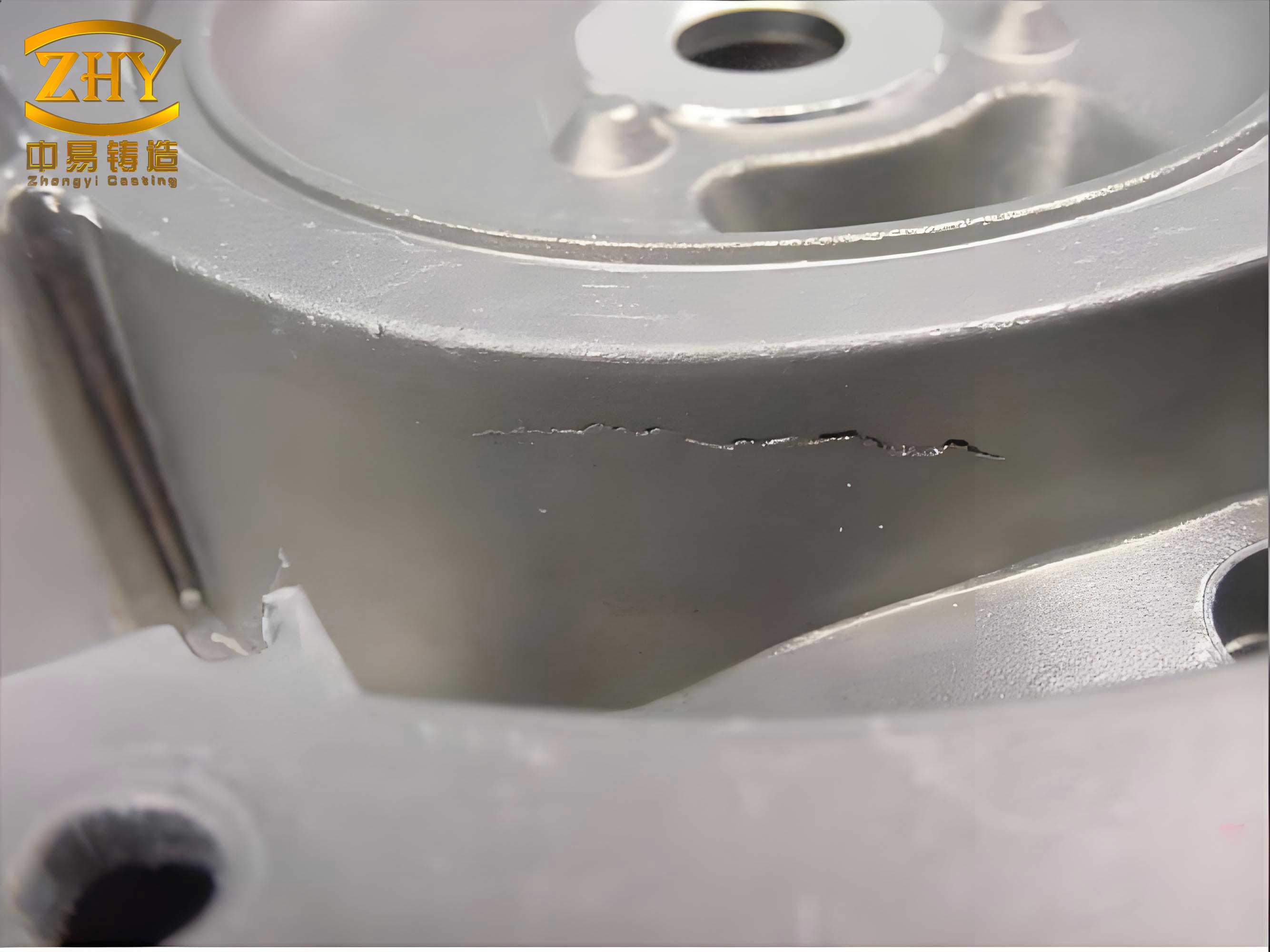
Initial production employed a horizontal molding process with resin sand, featuring open risers on each flange and two separate sand risers at the central body to promote directional solidification. The gating system was designed for mid-plane filling with a pouring temperature of 1,580°C over 60 seconds. However, RT inspection revealed severe internal casting defects, including slag inclusions, gas porosity, and shrinkage porosity, localized at critical sections labeled a, b, and c in the casting, with defect depths up to 40 mm. These casting defects not only jeopardized mechanical performance but also led to high rejection rates, necessitating a thorough investigation.
To dissect the origins of these casting defects, I utilized advanced casting simulation software, analyzing solidification patterns, filling dynamics, and defect formation criteria. The simulation focused on porosity, microporosity, inclusion tracking, and velocity fields. The initial process showed a clear propensity for shrinkage defects at locations a and b, attributed to inadequate feeding from the sand risers. The feeding efficiency of sand risers is often limited, which can be quantified by the feeding efficiency factor η:
$$ \eta = \frac{V_{\text{effective feeding}}}{V_{\text{total shrinkage}}} $$
where \( V_{\text{effective feeding}} \) is the volume of liquid metal supplied by the riser to compensate for shrinkage, and \( V_{\text{total shrinkage}} \) is the volumetric shrinkage of the casting. For sand risers, η is typically low (around 10-15%), whereas exothermic risers can achieve 25-30%. In this case, the sand risers failed to provide sufficient feed metal, leading to shrinkage porosity, a common category of casting defects. The Niyama criterion, widely used to predict shrinkage porosity, is expressed as:
$$ G / \sqrt{T} < C $$
where \( G \) is the temperature gradient (°C/mm), \( T \) is the local solidification time (s), and \( C \) is a material-dependent constant. Simulation results indicated that at sites a and b, the Niyama value fell below the critical threshold, confirming susceptibility to shrinkage casting defects.
Regarding slag inclusions and gas porosity at locations a and c, the filling analysis revealed turbulent flow patterns. The original gating had two 60 mm ingates and one 100 mm sprue, with a 70 mm ladle nozzle. During pouring, the sprue remained unfilled, causing air aspiration and severe oxidation. The inclusion tracking module simulated the movement of oxide particles, showing accumulation at the defect sites. The ingate velocity \( v \) was calculated as:
$$ v = \frac{Q}{A_{\text{ingate}}} $$
where \( Q \) is the volumetric flow rate (m³/s) and \( A_{\text{ingate}} \) is the total ingate cross-sectional area. With two ingates, \( v \) reached 0.8 m/s, exceeding the recommended threshold of 0.6 m/s for steel castings, leading to jetting and splash that entrapped oxides. Additionally, the ingate placement on two flanges caused backflow when filling the third flange, further promoting slag entrainment. These factors collectively contributed to slag inclusion casting defects, while gas porosity likely arose from mold gas evolution due to inadequate venting in thick sections.
| Defect Type | Location | Root Cause | Simulation Criterion |
|---|---|---|---|
| Shrinkage Porosity | a, b | Inadequate riser feeding efficiency | Porosity, Niyama < C |
| Slag Inclusions | a, c | High ingate velocity, unfilled sprue, turbulent flow | Inclusion diameter > threshold, high absolute velocity |
| Gas Porosity | a, c | Mold gas entrapment, oxidation from air aspiration | Gas concentration models |
Based on this analysis, I formulated a comprehensive optimization strategy targeting feeding, filling stability, and gating design to eliminate these casting defects. The modifications were simulated prior to implementation to validate efficacy.
First, to address shrinkage casting defects, I replaced the two sand risers at locations a and b with a single elliptical exothermic riser. Exothermic risers enhance feeding by maintaining higher thermal gradients and providing additional heat, thereby increasing η. The required riser volume \( V_{\text{riser}} \) can be estimated using the modulus method:
$$ M_{\text{riser}} = k \cdot M_{\text{casting}} $$
where \( M \) is the geometric modulus (volume/surface area) and \( k \) is a factor typically 1.1-1.2 for exothermic risers. Simulation of the optimized design showed a significant reduction in porosity indicators, with Niyama values above critical levels.
Second, I redesigned the gating system to promote laminar flow and reduce oxidation. The sprue diameter was reduced from 100 mm to 80 mm to ensure it remains full during pouring, minimizing air contact. A slag trap or sprue well was incorporated at the base of the sprue to capture initial oxidized metal. The number of ingates was increased to four, each 60 mm in diameter, arranged using a bifurcated runner system to ensure balanced flow to all three flanges. This lowered the ingate velocity to 0.5 m/s, within the safe range. The Reynolds number \( Re \) for flow in ingates, indicative of turbulence, is given by:
$$ Re = \frac{\rho v D}{\mu} $$
where \( \rho \) is density, \( v \) is velocity, \( D \) is diameter, and \( \mu \) is viscosity. Keeping \( Re \) below 2,000 promotes laminar flow, reducing casting defects. The optimized gating layout ensured a steady, progressive filling pattern without backflow or jetting.
| Parameter | Initial Process | Optimized Process | Impact on Casting Defects |
|---|---|---|---|
| Riser Type | Sand risers (2) | Exothermic riser (1 elliptical) | Improves feeding, reduces shrinkage |
| Sprue Diameter | 100 mm | 80 mm | Prevents air aspiration, less oxidation |
| Ingate Number | 2 | 4 | Balances flow, lowers velocity |
| Ingate Velocity | 0.8 m/s | 0.5 m/s | Reduces turbulence and slag entrainment |
| Gating Layout | Mid-plane, unbalanced | Bifurcated with slag trap | Ensures平稳 filling, traps inclusions |
Third, I implemented supplementary measures in production to combat gas-related casting defects. Thick sections were rammed with chromite sand to improve heat dissipation and reduce gas evolution. A zircon-based alcohol coating of 2 mm thickness was applied to mold surfaces to enhance surface finish and minimize gas penetration. Multiple vent channels were integrated into cores to facilitate gas escape. These steps, combined with controlled pouring practices, aimed to mitigate gas porosity casting defects.
The optimized process was rigorously simulated using the same software, with a focus on defect prediction criteria. The results demonstrated a dramatic improvement: the porosity and microporosity maps showed no indications of shrinkage in critical areas, while inclusion tracking revealed minimal slag particle accumulation, confined mostly to the slag trap. The filling sequence exhibited a calm, upward progression with uniform temperature gradients. Key simulation outputs are summarized in Table 4, confirming the reduction in casting defects propensity.
| Simulation Criterion | Result | Interpretation |
|---|---|---|
| Porosity Index | Below critical level | No shrinkage casting defects expected |
| Niyama Criterion | G/√T > C everywhere | Adequate feeding, solidification integrity |
| Inclusion Area Fraction | < 0.1% in casting body | Negligible slag inclusion casting defects |
| Maximum Velocity | 0.5 m/s at ingates | Laminar flow, no turbulence |
| Temperature Gradient | Steady from bottom to riser | Directional solidification achieved |
Following simulation approval, I conducted production trials with the optimized process. The casting was produced under controlled conditions: resin sand molding, chromite sand in thick areas, coated molds, and vented cores. Pouring was performed at 1,580°C over 60 seconds, with careful monitoring. After shakeout and heat treatment, the castings underwent full RT inspection. The results were conclusive: no internal casting defects exceeding ASME Level II standards were detected. All specimens passed the hydrostatic test at 42.5 MPa without leakage, meeting the stringent requirements. This success validates the effectiveness of the optimization in eliminating the previously pervasive casting defects.
In conclusion, this case study highlights a systematic approach to addressing complex casting defects in high-pound class valve bodies. The integration of simulation software enabled precise identification of defect root causes, guiding targeted工艺 modifications. Key takeaways include: the adoption of exothermic risers to enhance feeding and prevent shrinkage casting defects; the design of gating systems with bifurcated runners, slag traps, and controlled ingate velocities below 0.6 m/s to ensure tranquil filling and minimize slag inclusion casting defects; and the use of specialized sands, coatings, and venting to reduce gas porosity casting defects. By simulating processes beforehand using criteria like porosity, Niyama, and inclusion tracking, foundries can significantly improve first-pass yield and produce high-integrity castings for critical applications. Future work may explore advanced feeding mechanisms or real-time process monitoring to further refine defect control, but the principles outlined here provide a robust framework for mitigating casting defects in large-scale steel castings.