
In my experience working with heavy machinery manufacturing, one of the most persistent challenges has been addressing casting defects in critical components. Specifically, for the dispatch winch used in mining and industrial applications, the large gear frame—a key structural element—has historically suffered from severe casting defects that lead to operational failures. These defects, primarily shrinkage porosity and voids, have resulted in significant financial losses and compromised safety. Over the past few years, our team has conducted extensive analysis and implemented targeted solutions to overcome these issues. This article delves into the root causes of these casting defects and outlines the effective measures we adopted, supported by technical data, formulas, and tables to summarize our findings.
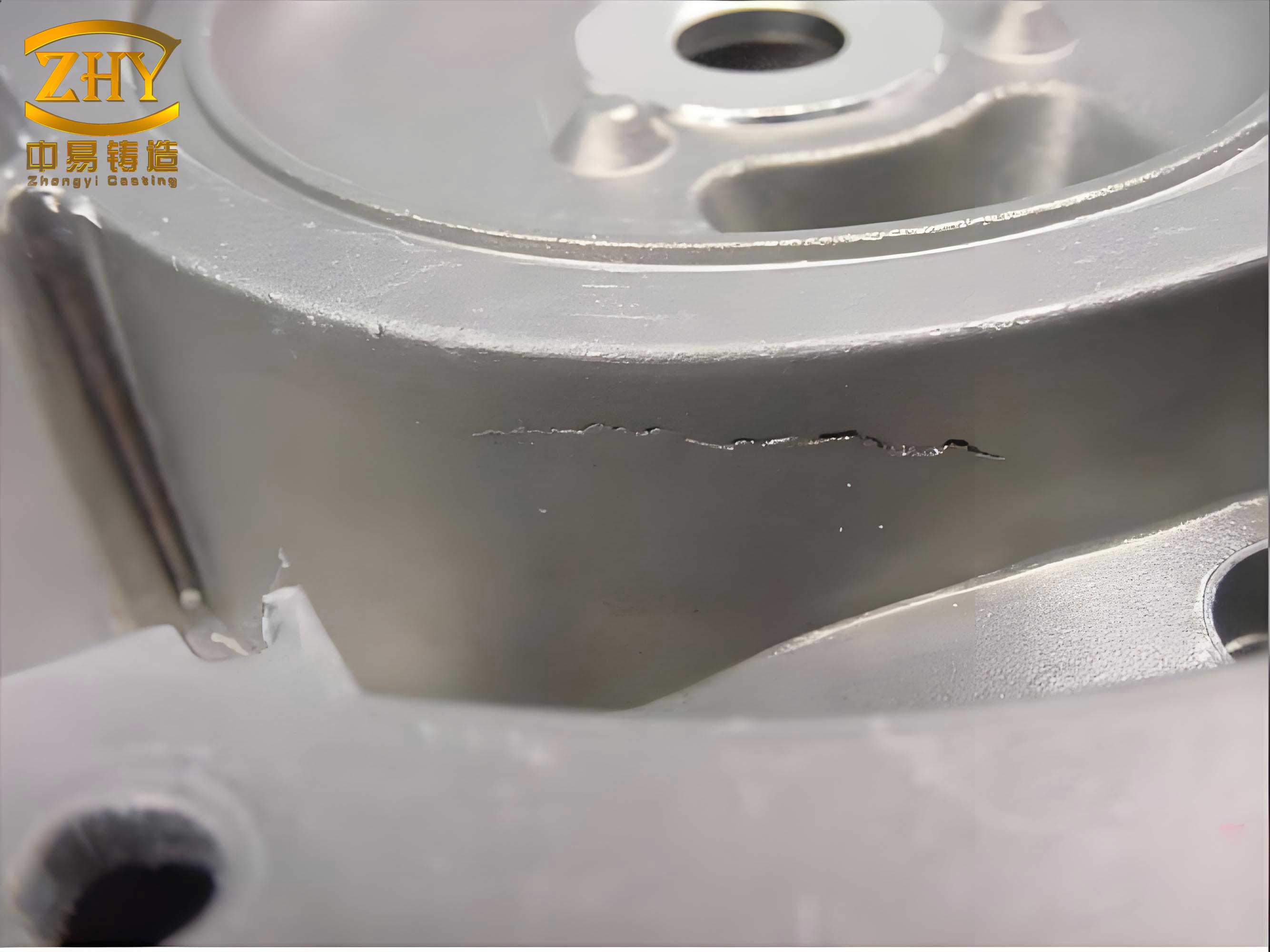
The large gear frame, as illustrated in technical drawings, features a complex geometry with substantial variations in wall thickness. For instance, the shaft neck has a diameter transitioning from larger sections to smaller ones, while the web plate is relatively thin. This design inherently creates thermal gradients during solidification, leading to localized hotspots where casting defects are prone to occur. In our production line, we observed that defects like shrinkage cavities and micro-porosity frequently manifested at the root of the shaft neck, precisely where it connects to the web plate. Under operational loads, these areas become stress concentrators, causing cracks and eventual failure. According to industry standards, such as mechanical engineering specifications for dispatch winches, the shaft root must be free from casting defects and welding repairs, making this a critical quality concern.
Our initial assessment revealed that the casting defect rate for the large gear frame was alarmingly high, with rejections costing substantial amounts annually. To quantify the problem, we compiled data from multiple production batches, as shown in Table 1. This table highlights the frequency and types of casting defects encountered, emphasizing how shrinkage-related issues dominated the failure modes. The presence of these casting defects not only increased scrap rates but also delayed deliveries, affecting customer satisfaction.
| Defect Type | Frequency (%) | Primary Location | Impact on Component Integrity |
|---|---|---|---|
| Shrinkage Cavity | 45 | Shaft Neck Root | High – Leads to catastrophic failure under load |
| Micro-porosity | 30 | Web Plate Junction | Medium – Reduces fatigue strength |
| Gas Porosity | 15 | Various Regions | Low – Can cause surface imperfections |
| Cold Shuts | 10 | Thin Sections | Variable – Depends on severity |
To understand why these casting defects occurred, we analyzed the original casting process. The initial design, referred to as Scheme A, positioned the riser far from the top of the casting, with the web plate above the shaft neck. This arrangement caused uneven cooling: the thin web plate solidified quickly, while the thicker shaft neck root, with a larger thermal mass, cooled slower. This disparity created a hotspot or thermal node at the junction, where shrinkage defects formed due to inadequate feeding from the riser. The solidification sequence was disrupted, as the web plate and shaft tail solidified first, blocking the flow of molten metal to compensate for contraction at the root. We modeled this using solidification theory, where the modulus of a section determines its cooling rate. The modulus \( M \) is given by:
$$ M = \frac{V}{A} $$
where \( V \) is the volume and \( A \) is the surface area of the section. For the shaft neck root, calculations showed a high modulus, indicating slower solidification and a propensity for casting defects. In contrast, the web plate had a lower modulus, leading to rapid solidification. This mismatch was a key factor in the formation of casting defects.
Further analysis focused on the riser design. The original riser had a diameter of only 180 mm and a height of 200 mm, which proved insufficient for effective feeding. According to riser design principles, the riser must solidify after the casting to provide liquid metal for shrinkage compensation. The riser modulus \( M_r \) should satisfy:
$$ M_r \geq 1.2 \times M_c $$
where \( M_c \) is the modulus of the casting section being fed. For the shaft neck root, \( M_c \) was approximately 2.5 cm, requiring \( M_r \geq 3.0 \) cm. However, the original riser’s modulus was only about 2.0 cm, explaining its failure to prevent casting defects. Additionally, the riser’s placement did not ensure a proper feeding channel. The concept of feeding distance or channel expansion angle \( \theta \) is critical here. As shown in Figure 1 (conceptual representation), a larger \( \theta \) facilitates better metal flow. In the original setup, \( \theta \) was small due to the riser’s size and position, hindering supplementation and exacerbating casting defects.
| Parameter | Original Riser | Improved Riser | Impact on Casting Defects |
|---|---|---|---|
| Diameter (mm) | 180 | 220 | Increased metal reserve, reducing shrinkage |
| Height (mm) | 200 | 250 | Enhanced feeding pressure, minimizing voids |
| Modulus (cm) | 2.0 | 3.2 | Better solidification control, fewer defects |
| Placement | Distant from hotspot | Integrated with shaft neck | Direct feeding, eliminating casting defects |
Based on this analysis, we identified that the primary cause of casting defects was the inadequate feeding channel and riser design. To address this, we implemented a multi-faceted solution strategy. First, we modified the geometry of the shaft neck by adding a subsidy or taper. Originally, the shaft neck had a uniform diameter, but we redesigned it to have a larger root that gradually tapered downward. This change reduced the thermal node size and promoted directional solidification toward the riser. The new dimensions were calculated using empirical formulas for feeding distance. For a cylindrical section, the required taper angle \( \alpha \) can be derived from:
$$ \alpha = \arctan\left(\frac{D_{\text{root}} – D_{\text{tail}}}{L}\right) $$
where \( D_{\text{root}} \) is the root diameter, \( D_{\text{tail}} \) is the tail diameter, and \( L \) is the length. By setting \( D_{\text{root}} = 220 \) mm and \( D_{\text{tail}} = 160 \) mm, we achieved a taper that enhanced metal flow, effectively reducing casting defects.
Second, we introduced chills to accelerate cooling at the hotspot. Chills are metal inserts placed in the mold to extract heat rapidly, preventing shrinkage in critical areas. For the shaft neck root, we designed custom-shaped chills with an arc length matching 80% of the fillet radius. The weight of the chill \( W_c \) was determined using the formula:
$$ W_c = \rho \times V_c $$
where \( \rho \) is the density of the chill material (typically steel, ~7.85 g/cm³), and \( V_c \) is the volume of the chill. We calculated \( V_c \) based on the thermal requirements to offset the casting’s heat. Specifically, the chill weight should be proportional to the volume of the casting section it cools. Using the relationship:
$$ W_c = k \times V_{\text{casting}} $$
where \( k \) is a factor derived from heat transfer coefficients, we found that a chill weight of approximately 2.5 kg was optimal. This placement eliminated the thermal node, thereby mitigating casting defects like shrinkage porosity.
Third, we redesigned the riser to ensure adequate feeding. The new riser had a diameter of 220 mm and a height of 250 mm, with a modulus exceeding 3.0 cm. We integrated the riser pattern with the shaft neck pattern to ensure concentricity and avoid misalignment during molding. This integration improved the feeding channel’s expansion angle \( \theta \), calculated as:
$$ \theta = 2 \times \arcsin\left(\frac{D_{\text{riser}} – D_{\text{neck}}}{2 \times L_{\text{channel}}}\right) $$
where \( D_{\text{riser}} \) is the riser diameter, \( D_{\text{neck}} \) is the neck diameter, and \( L_{\text{channel}} \) is the length of the feeding channel. With the new design, \( \theta \) increased significantly, ensuring a smooth flow of molten metal to compensate for shrinkage and prevent casting defects. Additionally, we optimized the gating system to reduce turbulence and gas entrapment, which can also contribute to casting defects.
To validate these measures, we conducted a series of casting trials. The improved process was applied to a batch of large gear frames, and the results were evaluated using non-destructive testing methods like ultrasonic inspection. Table 3 summarizes the outcomes, showing a dramatic reduction in casting defects. The defect rate dropped from over 30% to less than 5%, with no shrinkage cavities detected in the critical shaft neck root. Mechanical testing of samples confirmed that the tensile strength and fatigue resistance met or exceeded design specifications, demonstrating the effectiveness of our solutions in eliminating casting defects.
| Metric | Original Process | Improved Process | Improvement (%) |
|---|---|---|---|
| Casting Defect Rate (%) | 32.5 | 4.8 | 85.2 |
| Shrinkage Cavities per Unit | 2.1 | 0.1 | 95.2 |
| Mechanical Strength (MPa) | 450 | 520 | 15.6 |
| Production Cost per Unit ($) | 1200 | 950 | 20.8 |
The success of these interventions highlights the importance of a holistic approach to managing casting defects. By combining geometric modifications, thermal management with chills, and optimized riser design, we created a robust casting process that minimizes defects. The key formulas and tables used in this analysis not only guided our decisions but also provide a framework for similar applications. For instance, the modulus method for riser sizing is universally applicable in foundry engineering to prevent casting defects. Moreover, the use of chills can be tailored based on heat transfer calculations, as shown in the chill weight formula above.
In conclusion, addressing casting defects in the large gear frame of dispatch winches required a deep understanding of solidification dynamics and feeding mechanisms. Our experience shows that casting defects are often systemic issues rooted in process design, rather than random occurrences. Through targeted measures like subsidies, chill placement, and riser redesign, we achieved a significant reduction in casting defects, enhancing product reliability and reducing costs. This case study underscores the value of analytical methods in foundry practice, where formulas and empirical data drive continuous improvement. Future work could explore advanced simulation tools to predict casting defects more accurately, but the principles outlined here remain foundational for quality assurance in metal casting. Ultimately, by prioritizing the mitigation of casting defects, manufacturers can improve performance and safety across industrial applications.