
In the pursuit of higher quality and more efficient production, modern foundries are increasingly transitioning from traditional cupola melting to medium frequency induction furnaces. This shift brings significant advantages, including precise control over composition and temperature, reduced environmental impact, and lower operational intensity. However, the fundamental change in the metallurgical characteristics of the molten iron introduces a new set of challenges, primarily manifesting as an increased propensity for various casting defects. My experience in process optimization has revealed that iron melted in an induction furnace tends to have fewer nucleation sites, greater undercooling, and a pronounced tendency towards shrinkage and carbide formation compared to its cupola-melted counterpart. Effectively managing these inherent properties is paramount to producing sound castings. This article consolidates practical strategies and theoretical insights for preventing common casting defects, drawing from systematic investigations into issues such as shrinkage porosity, cracking, and undesirable graphite structures.
The nature of casting defects is deeply rooted in the solidification dynamics and the冶金 quality of the iron. In medium frequency furnaces, the intense stirring and high superheating temperatures result in a very pure, clean melt. While beneficial for reducing inclusions, this purity eliminates many potential nucleation sites that are naturally present in cupola iron, such as certain sulfides and oxides. This leads to what is often termed a “metallurgically quiet” melt. Upon pouring, such a melt exhibits increased undercooling before solidification begins. The consequence is a shift in the graphite morphology and a change in the solidification mode. For gray iron, this often means a reduction in the desirable Type A graphite and an increase in undercooled graphite types (Type D and E), which are associated with poorer mechanical properties and increased shrinkage tendency. The relationship between undercooling (ΔT) and nucleation potency can be conceptually framed by considering the free energy barrier for nucleation, ΔG*:
$$
\Delta G^* = \frac{16\pi\gamma^3}{3(\Delta G_v)^2}
$$
Where \(\gamma\) is the interfacial energy and \(\Delta G_v\) is the volume free energy change, which is a function of undercooling. A higher effective undercooling due to a lack of nuclei promotes this energy barrier, leading to fewer, but potentially larger, eutectic cells and the associated problems. The table below summarizes the key differences in iron characteristics and their link to specific casting defects.
| Furnace Type | Melt Characteristic | Primary Related Casting Defects | Typical Location in Casting |
|---|---|---|---|
| Cupola | High nucleation potential, presence of impurities | Slag inclusions, higher variability | Random, near gating systems |
| Medium Frequency Induction | Low nucleation potential, high purity, controllable chemistry | Shrinkage porosity, cracking, carbides (chill), undesired graphite (D/E) | Thick sections, junctions (hot spots), thin walls |
A critical defect family stemming from these changes is shrinkage porosity and its severe form, shrinkage cavities. These defects occur because the volume contraction during solidification is not adequately compensated by feed metal. The problem is exacerbated in induction-melted iron due to its longer liquidus-to-solidus time (mushy zone) and the糊状凝固 mode promoted by the changed graphite formation. The total volume shrinkage, \( V_{shrinkage} \), from pouring to room temperature can be broken down into three stages:
$$
V_{shrinkage} = V_{liquid\ contraction} + V_{liquid-solid\ contraction} + V_{solid\ contraction}
$$
For gray iron, the expansion from graphite precipitation can partially offset the \( V_{liquid-solid\ contraction} \). However, if the mold wall movement is excessive or the feeding path is blocked, internal shrinkage porosity forms. A practical case involved brake drum castings, where shrinkage defects persistently appeared in the reinforcing rib areas. Analysis showed these were the last regions to solidify. The initial gating and risering system failed to establish a proper temperature gradient for directional solidification towards the riser.
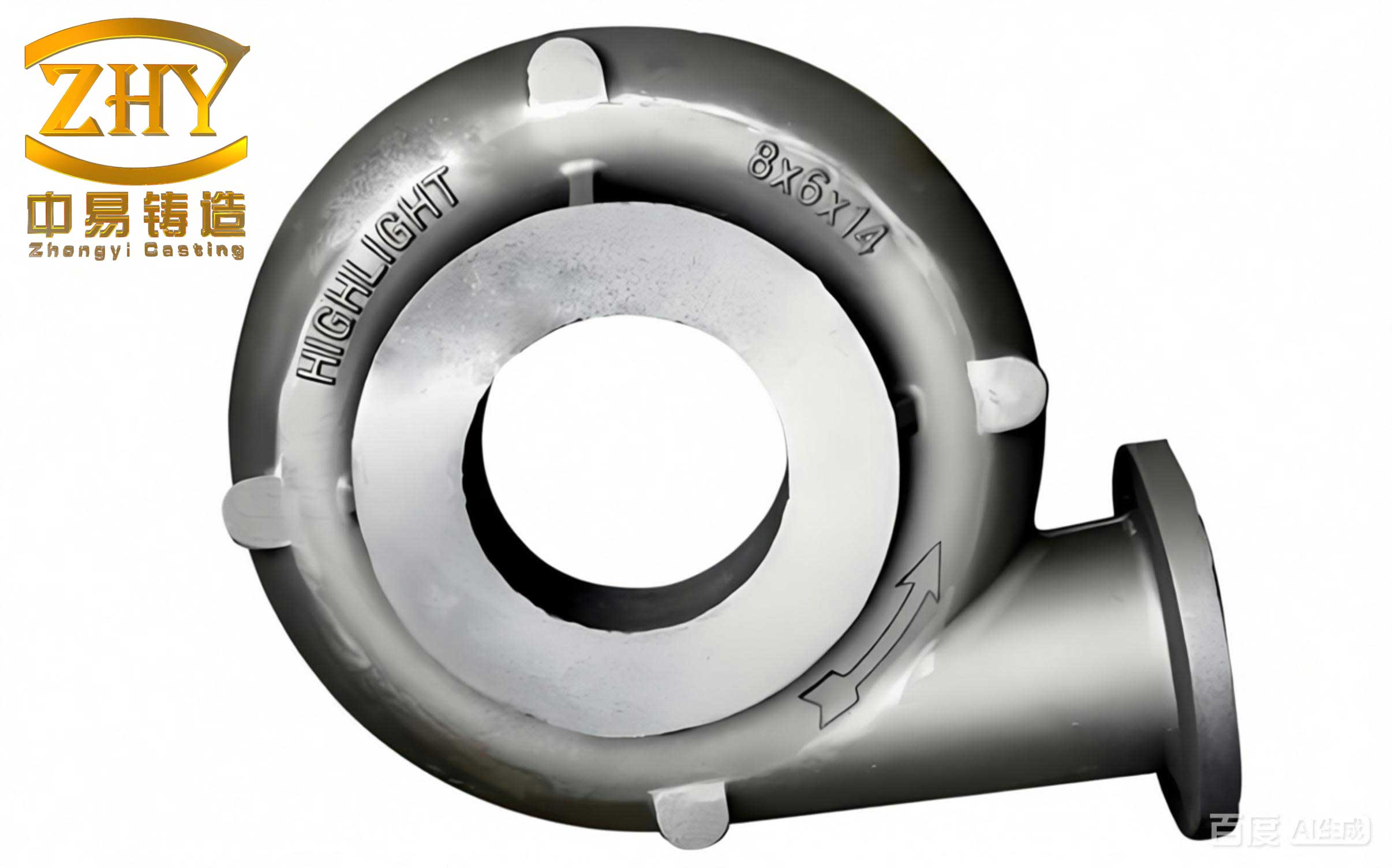
The solution was a multi-pronged approach targeting both thermal and冶金 controls. First, the gating system was redesigned using computer simulation software to visualize the solidification sequence. This led to the implementation of side risers that provided sufficient feed metal volume. Secondly, a blind riser was added directly onto the identified hot spot (the last-to-solidify area on the flange). This riser was positioned approximately 100 mm above the casting to ensure adequate metallostatic pressure head, overcoming the flow resistance within the mushy zone and maintaining positive pressure on the solidifying casting. The pressure head \( h \) required can be related to the feeding distance \( L_f \) and the morphology of the mushy zone, though it is often determined empirically. The combined effect was to successfully move the shrinkage defect from the casting body into the riser itself.
Beyond riser design, controlling冶金 factors is equally crucial in minimizing the shrinkage tendency. Key parameters include:
| 冶金 Parameter | Influence on Shrinkage | Recommended Control Strategy |
|---|---|---|
| Carbon Equivalent (CE) | Higher CE (approaching eutectic) reduces shrinkage. CE = %C + 0.33(%Si) + 0.33(%P) | Maintain CE slightly higher than for cupola melting. Use high-quality graphitic recarburizers. |
| Sulfur (S) Content | Very low S (<0.03%) reduces nucleation sites, increasing shrinkage. Optimal S promotes nucleation. | Intentional sulfidation to achieve 0.06-0.08% S for enhanced eutectic cell count. |
| Inoculation Practice | Over-inoculation can shorten the eutectic arrest and delay the end of solidification, extending feeding demand. | Use efficient inoculants (e.g., FeSi with Sr, Ba). Employ late stream inoculation to maximize effectiveness. |
| Mold Rigidity | Low rigidity allows mold wall movement, negating the beneficial expansion from graphite precipitation. | Use molds with high hardness (>90) to maximize expansion compensation. Balance with collapsibility. |
Another pervasive issue with induction-melted iron is the occurrence of hard spots, cracking, and unacceptable hardness differentials within a single casting. This is directly linked to the formation of undercooled graphite (Type D/E) and associated carbides, particularly in thin sections or at edges. The “hard edge” phenomenon, where the cope and drag halves of a casting show a hardness difference exceeding 30 HB, significantly increases residual stress and crack susceptibility. The mechanism involves rapid cooling in thin sections coupled with the low nucleation potential of the iron, leading to a carbide-promoting solidification sequence. To counteract this, strengthening inoculation is essential. Furthermore, adjusting the Silicon-to-Carbon ratio (Si/C) can be beneficial. A slightly higher ratio favors graphite formation over cementite. For thin-wall gray iron castings requiring HT200 or higher, one can apply the “undissolved graphite particle theory,” which involves adding a small percentage (1-2%) of pig iron into the pouring ladle to introduce native graphite particles as additional nucleation sites.
Managing iron that has experienced prolonged holding time in the furnace is another critical skill. Extended holding leads to “over-purification” and fading of inoculation effects, severely degrading nucleation potential. For such situations, the “pre-graphitization treatment” is effective. This involves charging a small amount of fresh charge materials (like pig iron and steel scrap) into the holding furnace and remelting it. This process regenerates fresh graphite nuclei within the superheated bath, effectively “re-activating” the melt’s nucleation ability and preventing the associated casting defects like shrinkage and coarse graphite.
The principles of controlling casting defects extend to ductile iron production as well, albeit with unique manifestations. A classic problem is “inverse chill” or “reverse chilling,” where carbides appear in the center of thick sections rather than at the chilled surface. This defect was observed in heavy-wall ductile iron castings like tractor front axles. Metallurgical analysis revealed severe silicon segregation. The surface, solidifying first, had a higher silicon content (e.g., 3.0%), promoting ferrite. The slowly solidifying center, depleted in silicon (e.g., 2.4%), was driven into the carbide-stable region of the phase diagram. The糊状凝固 characteristic of ductile iron exacerbates this microsegregation.
The countermeasures involve strict冶金 control and thermal management. First, the base iron silicon content must be kept low, typically between 1.1-1.4%. Silicon is then added during the spheroidizing and multiple inoculation stages (post-inoculation, stream inoculation). The final silicon content should be controlled below 2.8% to minimize the concentration gradient available for segregation. Secondly, the pouring system must be designed to minimize temperature gradients within the mold cavity. This involves strategic placement of gates and risers to promote more uniform cooling, thereby not creating the conditions for severe silicon偏析. The solidification time \( t_s \) for a simple shape can be estimated by Chvorinov’s rule:
$$
t_s = k \left( \frac{V}{A} \right)^n
$$
where \( V \) is volume, \( A \) is surface area, \( k \) is the mold constant, and \( n \) is an exponent (often ~2). Designing to minimize the \((V/A)\) ratio variations within the casting helps achieve more uniform solidification.
The choice and use of recarburizer are fundamental when producing synthetic iron with high steel scrap ratios (often 30-40%). The recarburizer must be high-temperature treated, graphitic carbon. Amorphous carbon recarburizers can adversely affect nucleation and graphitization. Three principles govern effective recarburization: (1) High superheat temperature (above 1420°C, ideally 1500-1550°C) for complete dissolution and absorption. (2) Strong搅拌, best achieved by charging the recarburizer at the furnace bottom with the initial charge. (3) Sufficient time at temperature, typically a 10-minute hold after reaching the target temperature, ensures near-complete absorption and avoids floatation losses.
In summary, the prevention of casting defects in a modern foundry using medium frequency induction melting requires a holistic understanding that intertwines furnace冶金, mold design, and process control. It is not merely a substitution of equipment but a complete reevaluation of the solidification science applied to a different material base. Key takeaways form a systematic defense against defects:
1. Acknowledge and compensate for the low nucleation potential of induction melted iron. Intentional sulfidation (to 0.06-0.08% S for gray iron) and powerful, late inoculation are non-negotiable practices.
2. Master the art of recarburization. Use graphitic carburizers, charge them early, melt at high temperature, and allow for absorption time to achieve stable and predictable carbon equivalents.
3. Design feeding systems with the knowledge that this iron has a greater shrinkage tendency. Use modulus calculations and solidification simulation to place adequate risers with proper pressure heads, and ensure high mold rigidity to utilize graphite expansion.
4. Actively manage melt holding times. Employ “pre-graphitization” for delayed pours to restore nucleation potential and avoid the associated defect risks.
5. For ductile iron, rigorously control base silicon and use multiple inoculation steps to prevent inverse chill caused by segregation in heavy sections.
6. For thin-wall gray iron castings prone to carbides and hard edges, consider adjusting the Si/C ratio and, in specific cases, the introduction of undissolved graphite nuclei via pig iron additions.
By integrating these strategies—from the careful selection of charge materials and additives to the sophisticated design of gating and risering systems—foundries can fully leverage the benefits of induction melting while robustly suppressing the entire spectrum of potential casting defects. The goal is a predictable process where the high quality of the melt translates directly into high integrity castings, free from the costly and performance-limiting imperfections of shrinkage porosity, cracks, and undesirable microstructures.