
Throughout my career in foundry engineering, addressing and preventing casting defects has been a central and persistent challenge. The production of high-integrity cast components, especially those with complex geometries and stringent performance requirements, demands a holistic approach that integrates design analysis, material science, and precise process control. The journey from recurrent failure to consistent success often hinges on a detailed understanding of how specific casting defects originate and the implementation of tailored countermeasures. In this account, I will share insights from the production of two distinct but instructively complex components: a large dredge pump body in cast iron and a thin-walled aluminum alloy pressure housing. Each case presents a unique set of challenges with casting defects at their core, and the solutions developed offer broadly applicable principles for defect mitigation.
Case Study I: The Large Dredge Pump Body – Combating Cold Shuts, Porosity, and Shrinkage
The first component was a critical cast iron pump body for dredging vessels. Its substantial size, intricate internal passages formed by extensive sand cores, and varying wall sections made it exceptionally prone to a suite of interrelated casting defects. Initial production runs were plagued by issues that compromised both the structural integrity and pressure tightness of the final castings.
Structural Challenges and Initial Defect Manifestation
The pump body’s design inherently created conditions favorable for defects. The large planar surfaces and thin flanges were susceptible to premature freezing, leading to cold shuts where metal streams failed to fuse. The massive core assemblies, necessary to form the internal volute, presented significant obstacles to gas evolution during pouring, creating a high risk for gas porosity (blowholes) and core burns. Furthermore, the thick sections at the suction and discharge nozzles, acting as isolated thermal masses, were natural hotspots where shrinkage porosity and voids would likely form if not properly fed. These are classic examples of geometry-induced casting defects.
Comprehensive Process Overhaul for Defect Elimination
To combat these issues, a multi-faceted process was developed, targeting each family of defects systematically.
1. Gating and Pouring System Redesign
The primary goal was to achieve rapid, tranquil, and sequential filling to prevent cold shuts and aid temperature gradient control. A step-gating system was implemented. The key to preventing turbulence-related casting defects like dross entrainment and gas aspiration lies in the design of the gating system. We employed a pressurized system to ensure rapid filling of thin sections, but carefully calculated the ratios to maintain control. The relationship between choke area, sprue, runner, and ingate areas is critical. A common approach is to use a non-pressurized (or slightly pressurized) system for iron to minimize turbulence. The design can be guided by the principle of maintaining a constant mass flow rate. The continuity equation is fundamental:
$$ Q = A_1 v_1 = A_2 v_2 $$
Where \( Q \) is the volumetric flow rate, \( A \) is cross-sectional area, and \( v \) is flow velocity. To reduce \( v \) at the ingates and thus turbulence, the total ingate area \( \Sigma A_{gate} \) should be the largest in the system. A typical ratio used for grey iron in green sand could be:
$$ A_{sprue-bottom} : \Sigma A_{runner} : \Sigma A_{gate} = 1 : 1.2 : 1.4 $$
For the pump body, a stepped design ensured the lower gates filled the thick sections first, establishing a favorable thermal gradient, while upper gates prevented freezing across the large flat surfaces. Pouring time was scientifically determined based on the casting weight and section thickness to balance fill velocity against thermal loss.
| Parameter | Specification | Rationale |
|---|---|---|
| Gating Type | Step-Gating (Bottom + Upper Gates) | Sequential fill, prevents cold shuts in thin, large areas. |
| System Pressurization | Moderately Pressurized | Ensures complete filling; controlled via area ratios. |
| Target Pouring Time | 25-35 seconds | Calculated from weight/section thickness to minimize heat loss and turbulence. |
| Ingate Velocity | < 0.5 m/s | Minimizes mold erosion and air entrainment. |
2. Advanced Mold and Core Making Techniques
The core assembly was the other critical battlefield against casting defects, specifically gas-related ones. Standard sand mixes were insufficient.
- Core Sand: For the main volute cores and any cores adjacent to thick sections (like the pump casing’s lettering), zircon sand was used due to its superior thermal conductivity and resistance to sintering. This reduced the risk of veining and burn-on defects.
- Venting: This was paramount. Multiple venting strategies were combined:
- Straw ropes (≥6 strands) were tied around core irons to create permanent, collapsible vent channels leading directly to the core prints.
- Vents (Ø60 mm) were placed in the cope at the core print locations to provide an external escape path for gases.
- Loose straw bundles were placed within the core bodies during making to enhance both venting and core collapsibility during cooling, preventing hot tearing.
- Specialized Sands for Critical Areas: The riser necks (hot spots) were made from high-purity silica or other high-refractoriness sand to resist erosion. The core for the lifting hole, a small but critical feature, was also made from zircon sand for durability and surface finish.
The permeability of the sand, crucial for venting, can be expressed as a function of pore space. While direct measurement is standard, the dependency on grain size and distribution is key. The pressure drop \( \Delta P \) across a core of length \( L \) for a gas flow rate \( Q_g \) is related to permeability \( K \) by a form of Darcy’s law:
$$ \Delta P = \frac{\mu L}{K A} Q_g $$
where \( \mu \) is the gas viscosity and \( A \) is the cross-sectional area. High permeability \( K \) is essential to minimize back-pressure that can force gas into the metal, causing porosity defects.
3. Melting, Treatment, and Pouring Discipline
Ladle treatment before pouring was aimed at reducing dissolved gases, a primary source of pinhole porosity defects. An addition of 0.6% Aluminum and 0.2% Calcium-Silicon was made to the ladle for degassing. The practice of “slag-carrying tap” was used to help flux impurities. Ladle drying and preheating to a dull red heat (~600°C) were strictly enforced to prevent hydrogen pickup from moisture. Temperature control was precise: a tap temperature of 1450-1480°C, with a pouring temperature of 1400-1430°C, allowing a brief holding time in the ladle for further dross flotation. A summarized process flow is below.
| Process Step | Parameter / Action | Purpose |
|---|---|---|
| Ladle Treatment | 0.6% Al + 0.2% CaSi addition | Degassing to reduce pinhole porosity defects. |
| Tap Practice | Iron and slag tapped together | Initial slag formation and impurity removal. |
| Ladle Condition | Thoroughly dried, preheated to >600°C | Eliminates moisture source for hydrogen porosity. |
| Temperature | Tap: 1450-1480°C; Pour: 1400-1430°C | Provides sufficient fluidity while minimizing liquid shrinkage and gas solubility. |
| Pouring | Quiet transfer after brief holding | Allows slag to rise; minimizes turbulence. |
4. Solidification and Post-Casting Control
The shakeout (mold removal) was delayed until the casting temperature was below 200°C to prevent distortion and the formation of high-stress conditions that could exacerbate micro-shrinkage or promote cracking. The entire cleaning and heat treatment sequence was standardized to ensure dimensional stability and required mechanical properties.
The success of this integrated approach was evident. The recurrent casting defects—cold shuts, gas holes, and shrinkage porosity—were virtually eliminated. The castings exhibited excellent surface finish, sound internal integrity as confirmed by non-destructive testing, and reliable performance in service, demonstrating that a systematic, physics-based approach can reliably overcome even the most daunting casting defects.
Case Study II: The Thin-Walled Aluminum Alloy Shell – Solving Shrinkage Porosity in a Precision Casting
The second component presented a different universe of challenges: a thin-walled, complex aluminum alloy (ZL115A) pressure shell for a high-performance product. The primary and devastating issue was shrinkage porosity, leading to a 70% rejection rate during initial X-ray inspection. This case highlights how subtle design and process interactions can dominate the formation of specific casting defects.
Structural Analysis and the Root of the Problem
The shell was a cylindrical component with a nominal wall thickness of 5mm but featured numerous isolated heavy sections (bosses, mounting pads). The most problematic area was a circumferential flange (Area ‘A’ in the original diagram), which had a massive as-cast thickness of 21mm due to generous machining allowances (10mm on the outer diameter). This created a severe isolated thermal mass, or hot spot. In the original counter-gravity (low-pressure) casting process, this area was inadequately fed: it was too far from the main feeding source (the gate) and was itself a sink for shrinkage. The application of chills was insufficient to overcome the local thermal mass. The result was a concentrated zone of shrinkage porosity and micro-shrinkage, classic casting defects resulting from poor thermal modulus management.
A Multi-Pronged Strategy for Defect Mitigation
The solution required changes to the part design itself, the feeding strategy, and the metal treatment process.
1. Redesigning the Part for Castability
The most impactful change was to reduce the thermal mass of the problematic area. The external machining allowance on the flange was reduced from 10mm to a “follow-form” 4mm. This simple change decreased the as-cast thickness at that section from 21mm to 14mm, significantly reducing its solidification modulus and making it less prone to forming an isolated hot spot. The taper was also minimized. This demonstrates that collaboration with the design engineer to optimize the part for manufacturability is often the most effective first step in preventing casting defects.
2. Optimizing the Feeding and Gating System
The original vertical feeding system in the counter-gravity process was undersized for effective feeding over the long distance to the hot spot. The diameter of the central stalk (or “riser tube” in low-pressure casting) was increased from Ø55mm to Ø65mm, enhancing its feeding capacity. The connection to the part was via a vertical slot gate. To prevent this gate from creating a new hot spot at its base, its width was strictly controlled to 15mm, minimizing the volume of hot metal in direct contact with the casting at that junction. The gating system was designed to be “open,” promoting laminar flow. The key ratio principle was:
$$ \Sigma A_{stalk} < \Sigma A_{horizontal-runner} < \Sigma A_{slot-gate} $$
This ensured that the metal velocity decreased as it approached the mold cavity, minimizing turbulence and oxide formation, which are precursors to other types of casting defects like bifilms and inclusions.
3. Enhanced Metal Filtration and Treatment
To address potential non-shrinkage related defects like inclusions and oxide films that could be confused with or exacerbate shrinkage, a rigorous triple-filtration regime was implemented: a ceramic foam filter at the entry to the mold (stalk top), a second filter in the horizontal runner, and a fine mesh filter at the entrance to the vertical slot gate. Furthermore, a double degassing practice was adopted: once in the furnace and once in the holding crucible just before casting, drastically reducing dissolved hydrogen to prevent gas porosity from compounding the shrinkage issue.
4. Precise Solidification Control Parameters
The counter-gravity process parameters were fine-tuned. The fill pressure profile was set for a slow, steady rise of metal (1.3 kPa/s). The pouring temperature was tightly controlled at 720 ±10°C. Crucially, the pressure hold time after filling was extended to 8-10 minutes. This maintained metallostatic pressure on the solidifying metal, actively forcing liquid into incipient shrinkage pores and compensating for solidification contraction, which is the fundamental mechanism for reducing shrinkage-related casting defects. The pressure \( P \) applied during solidification directly influences the critical radius \( r^* \) of a pore that can nucleate, as described by a simplified form of the nucleation theory under an external pressure:
$$ \Delta P = P_{external} – P_{metalostatic} = \frac{2\gamma}{r^*} $$
Where \( \gamma \) is the surface tension. A higher applied \( P_{external} \) increases the required \( \Delta P \) for nucleation, effectively suppressing the formation of shrinkage voids.
| Aspect | Original Process | Improved Process | Impact on Casting Defects |
|---|---|---|---|
| Flange Design | 21mm thick (10mm allowance) | 14mm thick (4mm allowance) | Eliminated isolated hot spot, primary cause of shrinkage. |
| Feeding Stalk | Ø55 mm | Ø65 mm | Increased feeding capacity and range. |
| Gate Width | Not strictly controlled | Fixed at 15mm | Reduced localized overheating at gate connection. |
| Filtration | Single stage | Triple-stage filtration | Eliminated inclusion defects. |
| Degassing | Single treatment | Double degassing | Eliminated hydrogen porosity. |
| Hold Pressure Time | Insufficient | 8-10 minutes | Active feeding to suppress shrinkage porosity. |
The results were transformative. The rejection rate due to shrinkage porosity and associated casting defects flipped from over 70% to a yield of over 70%. Furthermore, the improved feeding efficiency and reduced machining allowance increased the overall casting yield (product weight / poured weight) by 21%, delivering significant economic benefit alongside quality assurance.
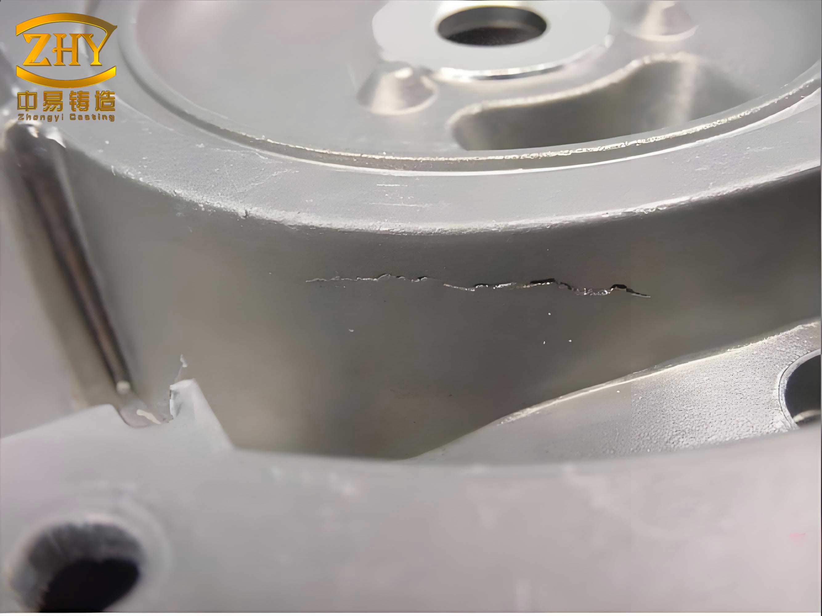
Unified Principles in the Fight Against Casting Defects
Analyzing these two disparate cases—a massive iron pump body and a precision aluminum shell—reveals common, fundamental principles in the science of preventing casting defects. These principles form a systematic framework for foundry engineers.
Thermal Management and Solidification Control
This is the paramount principle. Most severe casting defects like shrinkage porosity, hot tears, and distortion are rooted in uncontrolled solidification. The goal is to establish a predictable temperature gradient, directing solidification from the farthest points back toward the feeders (risers or feeding gates). Key tools include:
- Modulus Calculations: The geometric modulus (Volume/Surface Area) of a section predicts its solidification time. Feeders must have a larger modulus than the sections they feed. For a cylindrical feeder, its modulus \( M_f \) must satisfy:
$$ M_f = 1.2 \times M_c $$
where \( M_c \) is the modulus of the heaviest section being fed, to ensure it remains liquid longer. - Chills and Insulation: Used to locally alter the solidification rate. Chills (metal or graphite) increase cooling; insulating sleeves or exothermic pads on risers decrease it, extending feeding time.
- Directional Solidification Design: Both gating placement and casting orientation in the mold are chosen to promote this gradient.
The Hydraulics of Filling: Preventing Turbulence
A second major class of casting defects—gas entrainment, oxide bifilms, sand inclusion, and mistruns—originates during mold filling. The key is to achieve laminar or non-turbulent flow. This is governed by the Reynolds number \( Re \):
$$ Re = \frac{\rho v D}{\mu} $$
where \( \rho \) is density, \( v \) is velocity, \( D \) is hydraulic diameter, and \( \mu \) is viscosity. Keeping \( Re \) below a critical threshold (often around 2000 for ingates) is targeted through system design: using larger, tapered sprues; properly sized runners and filters; and bottom or step gating. The Bernoulli equation also informs the relationship between pressure and velocity at different points in the system, helping to avoid aspiration.
Gas Defect Prevention: A Multi-Front War
Gas-related casting defects (pinholes, blowholes, surface blisters) can come from the metal (hydrogen, nitrogen), the mold (moisture, organic binders), or from air entrapment. A combined strategy is essential:
| Gas Source | Defect Type | Preventive Countermeasures |
|---|---|---|
| Molten Metal (H₂, N₂) | Pinholes, subsurface porosity | Proper degassing (rotary, lance), use of dry, clean charge materials, controlled superheat. |
| Sand Mold/Core | Blowholes, core blows | Low-moisture molds, use of low-gas binders, adequate and designed venting (permeability, vent channels), core drying/baking. |
| Air Entrapment | Surface blows, turbulence defects | Laminar filling system design, proper mold venting at high points, avoiding “waterfall” effects in the mold. |
Material and Mold-Media Interaction
The chemical and physical interaction between the molten metal and the mold can lead to a range of surface and sub-surface casting defects. These include sand burn-on/penetration, metal penetration, and veining. The selection of mold and core sands is critical. The use of high-refractoriness sands like zircon, chromite, or specially coated silica sands creates a thermal and chemical barrier. The design of the sand mixture—its grain size distribution, binder type, and additive content—directly affects its resistance to these defects. The pressure at the metal-mold interface that can lead to penetration is related to the metallostatic head \( h \), metal density \( \rho \), and the effective pore size of the sand:
$$ P_{metal} = \rho g h $$
The sand’s resistance must be greater than this pressure, which is a function of its cohesiveness and the surface tension of the metal.
Conclusion: A Systematic Methodology
The journey with these two components underscores that casting defects are not random failures but the predictable consequences of physical laws acting on a specific process setup. Defect elimination is not about finding a single “magic bullet” but about implementing a systematic, integrated methodology:
- Analyze the Thermal Geometry: Identify hot spots, thin sections, and potential feeding obstacles. Calculate moduli.
- Design for Controlled Fill and Feed: Engineer the gating for laminar fill and the risering/feeding for directional solidification. Apply chills and insulation strategically.
- Engineer the Mold System for Function: Select appropriate sands and binders. Design and implement robust, multi-path venting for cores and mold cavities.
- Control the Metallurgical Quality: Implement disciplined melting, alloying, degassing, and filtration practices.
- Define and Control Process Windows: Establish and strictly adhere to critical parameters: pouring temperature, pouring time, holding pressure/time, shakeout temperature.
By viewing each casting project through this lens—where design, process, and material are inextricably linked—foundry engineers can diagnose the root causes of casting defects and implement effective, robust solutions. The dramatic improvements in yield and quality seen in both the massive dredge pump body and the delicate aluminum shell testify to the power of this physics-based, holistic approach to mastering the art and science of metal casting.