
In my extensive experience with permanent mold casting of aluminum alloys, few components have presented as consistent and challenging a set of issues as the motorcycle front damping cylinder. The part’s geometry—a long, thin-walled tube with a deep blind hole and integrated mounting lugs—combined with stringent pressure-tightness and surface quality requirements, makes it a prime candidate for a variety of casting defects. Achieving high yield rates demands not just following procedures, but understanding the intricate dance of metallurgy, thermodynamics, and fluid dynamics within the mold. This article distills my practical insights into the primary casting defects encountered, their root causes, and the integrated process controls necessary for their mitigation.
The journey to a sound casting begins long before the metal meets the mold. For alloys like ZL107 (a common choice for this application, similar to A356 with copper), melt preparation is the first and most critical line of defense against several casting defects. Hydrogen pickup is the arch-nemesis. Aluminum readily absorbs hydrogen from atmospheric moisture, and the solubility disparity between liquid and solid states is the fundamental driver for gas porosity. This relationship is governed by Sieverts’ law:
$$ [H] = K_H \sqrt{P_{H_2}} $$
where $[H]$ is the dissolved hydrogen concentration, $K_H$ is the equilibrium constant, and $P_{H_2}$ is the partial pressure of hydrogen. During solidification, the dissolved hydrogen is rejected and can form pores. If these pores are trapped just beneath the surface, they manifest as the dreaded subsurface blistering or pinholes. My protocol is rigorous: strict charge material control to avoid hydrated oxides, thorough furnace and tool pre-drying, and efficient rotary degassing using an inert gas like argon. The effectiveness is not just time-based; it’s verified by reduced pressure tests (RPT) to quantify hydrogen levels before any pour is authorized.
| Process Step | Key Parameters & Controls | Target Outcome | Notes from Experience |
|---|---|---|---|
| Charge Melting | Use dry materials; Avoid sudden temperature spikes (>750°C). | Minimize initial hydrogen absorption and oxidation. | Overheating dramatically increases hydrogen solubility and oxide generation. |
| Degassing | Rotary impeller, 0.3-0.5% Argon or N2, 8-12 minutes, 150-200 RPM. | Achieve hydrogen content < 0.15 ml/100g Al (RPT sample). | Visual observation of reduced bubble size/frequency in the melt is a good qualitative check. |
| Modification | Sr or Na based modifiers, precise addition per alloy weight, 5-10 min holding. | Transform eutectic Si morphology from acicular to fibrous. | Over-modification can lead to gas pickup; under-modification fails to improve mechanical properties. |
| Slag Removal | Use of certified fluxing agents, careful skimming, 10-15 min settling time. | Clear, mirror-like melt surface before transfer. | Residual flux or dross is a direct source of inclusion casting defects. |
| Transfer & Pouring | Pre-heated ladles (250°C+), gentle transfer, minimized turbulence. | Deliver clean, oxide-free metal into the gating system. |
Even with pristine melt, the casting process itself can reintroduce problems. The design of the gating and feeding system for a damping cylinder is unconventional. The common practice of using a vertical slot gate along the cylinder’s length and a top riser creates specific challenges. The initial metal stream can impinge on the core, causing turbulence that entrains air and forms oxides. These often get trapped at specific locations: the junction of the gate and cylinder body (often the low point during tilted pouring), the recesses around mounting lugs, and the area diametrically opposite the gate. These are the classic sites for oxide bi-film inclusions and associated subsurface porosity clusters.
My approach to combating these defects is multi-faceted. First, gating system design is optimized not just for feeding but for laminar fill. I often implement a choked sprue/runner system to control initial velocity, followed by an enlarged, tapered vertical gate to maintain a positive pressure head and reduce re-oxidation. Second, strategic use of vents and overflows is non-negotiable. Adding small vent slots at the top of the neck (the last area to fill) and a dedicated overflow opposite the main gate acts as a “trap” for the first, most oxide-laden metal and for escaping air. The mold’s parting lines must also be precisely machined to allow micro-venting without causing flash.
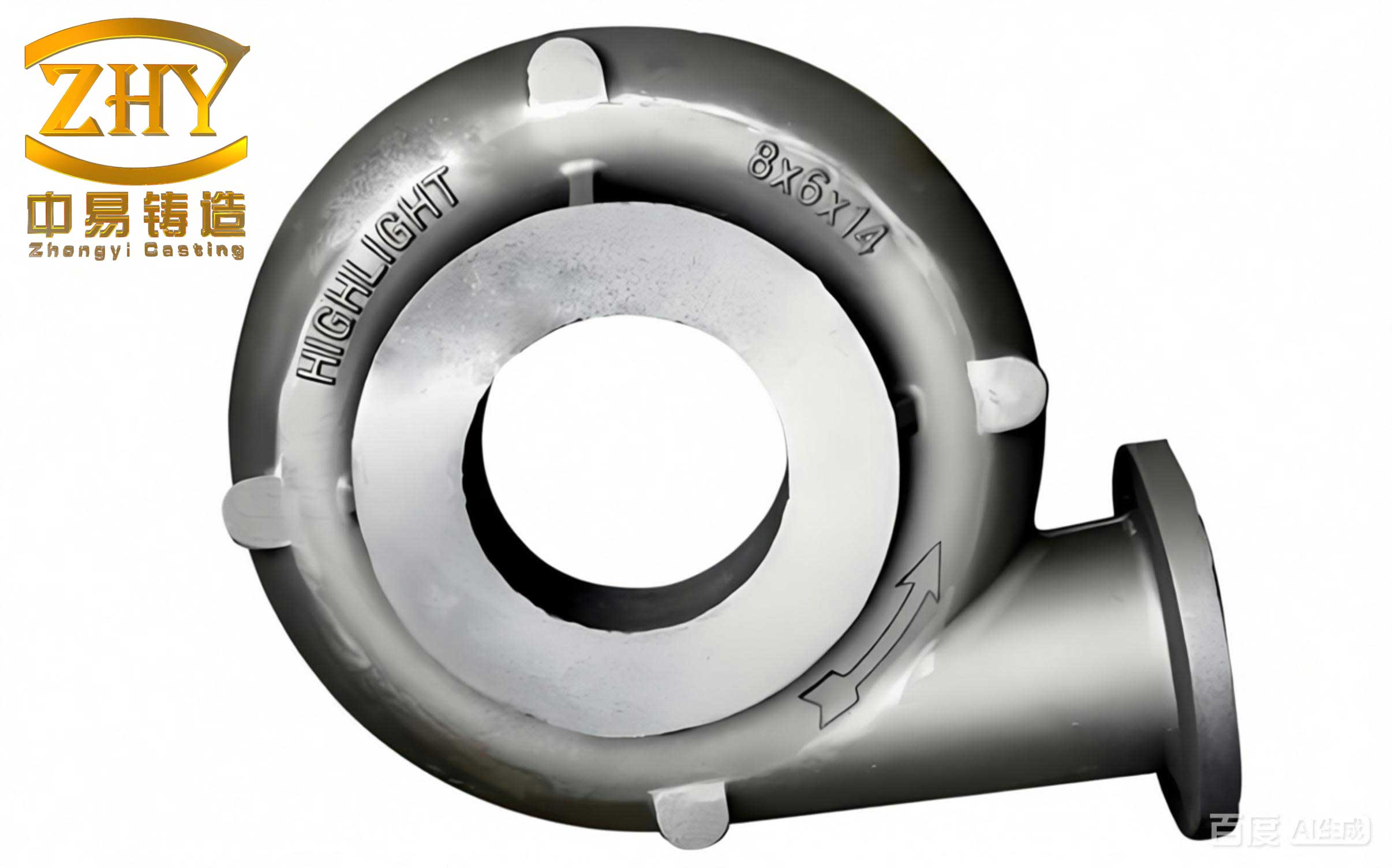
Perhaps the most technically demanding casting defects to address are those related to solidification shrinkage. The damping cylinder has several isolated thermal masses, or hot spots: the thick junction at the neck, the intersection of the lug and tube wall, and the bottom closure. In a directional solidification scheme aimed at feeding from the top riser, these hot spots can solidify last, leading to interdendritic shrinkage porosity (microshrinkage). When machined, especially for threaded holes in the lugs, this interconnected porosity becomes a leak path, failing the pressure test.
Since external chunky risers are not permissible for aesthetic and machining reasons, the strategy shifts to directional cooling control. The goal is to alter the local solidification time. This is achieved by manipulating the heat extraction rate at these hot spots. The solidification time $t_s$ for a simple shape can be approximated by Chvorinov’s rule:
$$ t_s = B \left( \frac{V}{A} \right)^n $$
where $V$ is volume, $A$ is surface area, $B$ is a mold constant, and $n$ is an exponent (typically ~2). To reduce $t_s$ at a hot spot, we can increase the local effective $A$ or increase $B$ (cooling rate). In practice, I employ two techniques on the mold (die): localized thinning of the mold wall at the hot spot to reduce its insulating effect, or the application of active spot cooling using compressed air or water mist channels. The cooling power required can be estimated from the heat that must be extracted:
$$ Q = m \cdot [C_p \cdot \Delta T + L_f] $$
where $Q$ is the total heat, $m$ is the mass of the hot spot, $C_p$ is the specific heat, $\Delta T$ is the superheat, and $L_f$ is the latent heat of fusion. Precise control of spot cooling onset and duration is critical to avoid creating a “chill” that induces premature tearing.
| Defect Type | Root Cause Analysis | Corrective & Preventive Actions | Process Control Parameters |
|---|---|---|---|
| Interdendritic Shrinkage (Porosity) | Poor directional solidification; Isolated hot spots solidifying last without feed metal. | 1. Local mold wall thinning. 2. Spot cooling (air/mist). 3. Optimized pouring temperature (lower end of range). 4. Enhanced thermal gradient via mold pre-heat zoning. |
Mold hot spot temperature (Thermocouple monitored); Coolant on/off time (s); Pour Temp. ±5°C. |
| Hot Tear / Transverse Crack | High thermal stress during late solidification when cohesion is low; Aggravated by impurity elements forming low-strength phases at grain boundaries. | 1. Strict control of Fe, Pb, Sn, Cd (Fe < 0.15% for pressure tightness). 2. Optimized core extraction time. 3. Uniform mold temperature. 4. Modification to refine grain structure. |
Chemical analysis per melt; Core pull time after pour; Mold temp. gradient < 30°C. |
| Cold Shut or Misrun | Insufficient metal fluidity; Early freezing in thin sections or long flow paths. | 1. Adjusted pour temperature (higher end). 2. Increased mold temperature. 3. Improved gating for shorter flow paths. 4. Check for excessive oxide films blocking flow. |
Mold pre-heat temperature; Metal fluidity test (spiral mold). |
The final category of critical casting defects is cracking. In damping cylinders, I have observed transverse cracks, often initiating at the root of a mounting lug near the gate. This is a classic hot tear. It occurs in the mushy zone when the partially solidified skeleton is subjected to tensile stresses that exceed its very low cohesive strength. The stress $\sigma$ arises from restricted contraction:
$$ \sigma = E \cdot \alpha \cdot \Delta T \cdot f(R) $$
where $E$ is Young’s modulus, $\alpha$ is the coefficient of thermal expansion, $\Delta T$ is the temperature drop, and $f(R)$ is a function of the restraint imposed by the mold and core. The long, steel core that forms the blind hole provides significant restraint. If the core is extracted too late, the solidified shell of the cylinder has already shrunk onto it, creating enormous stress during ejection. Furthermore, impurity elements like iron form hard, brittle intermetallic phases (e.g., $\beta$-Al5FeSi in plate-like morphology) that act as stress concentrators and crack initiation sites. The combined effect of stress and embrittled grain boundaries is catastrophic.
My prevention strategy is twofold: metallurgical and mechanical. Metallurgically, I enforce a strict impurity cap, particularly for iron. Manganese additions can be used to modify the iron phase morphology to a less harmful Chinese script form, but prevention is better. Mechanically, the timing of core extraction is fine-tuned through experimentation. The goal is to withdraw the core while the inner skin of the casting is still slightly plastic, minimizing the pulling force. This “window” is identified by monitoring the casting surface temperature at ejection and correlating it with the absence of tearing casting defects.
The interplay between these different casting defects cannot be overstated. For example, high hydrogen content not only creates pores but also exacerbates shrinkage porosity by nucleating voids that expand with residual liquid contraction. Similarly, oxide inclusions can act as initiators for cracks. Therefore, process control must be holistic. A sophisticated approach involves creating a Process Window Diagram for key parameters. For a damping cylinder, the two most critical interactive parameters are often pouring temperature ($T_p$) and mold preheat temperature ($T_m$). The viable process window is bounded by limits for different defects:
1. Upper $T_p$ limit: Set by increased gas solubility, excessive shrinkage, and mold erosion.
2. Lower $T_p$ limit: Set by cold shuts and misruns.
3. Upper $T_m$ limit: Set by slow solidification leading to coarse grains and severe shrinkage.
4. Lower $T_m$ limit: Set by cold shuts, excessive thermal shock, and premature freezing causing mistuns.
Within this window, there is a narrower “sweet spot” that simultaneously minimizes the risk for gas, shrinkage, and filling-related casting defects. Finding it requires systematic Design of Experiments (DOE).
Looking beyond traditional methods, the implementation of real-time monitoring and data analytics is the next frontier in conquering these casting defects. Thermocouples embedded in the mold at strategic locations (lug, neck, bottom) provide a solidification curve for each cycle. Deviations from the “golden curve” can predict subsurface shrinkage before the casting is even ejected. Pressure sensors in the hydraulic ejection system can detect abnormal sticking forces, signaling a potential for cracking or drag-related surface defects. By correlating this process data with final quality inspection results (X-ray, leak test), we can move from defect detection to defect prediction and prevention.
In conclusion, the high scrap rates historically associated with metal mold-cast motorcycle damping cylinders are not an inevitability. They are the consequence of complex, interacting physical phenomena manifesting as specific casting defects. A systematic, science-based approach that addresses the entire process chain—from raw material chemistry and melt treatment to gating design, thermal management of the mold, and precise control of cycle times—is essential. Each defect, be it subsurface porosity, shrinkage leakage, or hot tearing, has a clear mechanistic cause. By understanding these causes through the lens of solidification science and stress analysis, and by implementing corresponding targeted controls, it is entirely possible to achieve consistently high yields. The strategies outlined here, from degassing protocols and strategic venting to localized cooling and optimized extraction timing, form a proven toolkit for transforming this challenging component from a foundry headache into a model of reliable production.