
In our extensive experience within the metal casting industry, we have consistently observed that the quality of final cast components is profoundly influenced by precise control over both the casting process and subsequent heat treatment stages. Among the most critical challenges are heat treatment defects, which can manifest as distortions, residual stresses, soft spots, or microstructural inconsistencies, ultimately leading to component failure. This article, written from our firsthand perspective as developers and practitioners, delves into the sophisticated automation of casting sequences and the implementation of a microcomputer-based control system for heat treatment furnaces. Our primary objective is to elucidate how integrated process control can significantly mitigate heat treatment defects, enhance mechanical properties, and boost overall production efficiency. We will employ detailed tables, mathematical formulations, and system descriptions to provide a comprehensive overview.
The foundation of high-quality castings lies in repeatable and precise handling of molten metal. Our development of the J339 cylinder head metal mold casting成套设备 was driven by the need to move from manual, variable operations to automated, parameter-stable processes. Inconsistent pouring temperatures, inaccurate alloy quantification, and variable cycle times are direct precursors to defects that may only become apparent or be exacerbated during later heat treatment, contributing to a class of heat treatment defects related to inconsistent initial material conditions.
1. Automated Ladling and Extraction Sequence Programming
The automated ladle system and extraction manipulator form the core of the casting cell. Each action is triggered by positional or timing signals, ensuring a strict, repeatable sequence. This repeatability is the first line of defense against process-induced variations that could lead to casting flaws and subsequent heat treatment defects. The action sequences are programmed as follows.
1.1 Ladle System Action Sequence
The ladle operation is a multi-step process designed for precise molten aluminum alloy handling. The sequence is highly interdependent, where any deviation can affect the thermal history of the metal, influencing its response to heat treatment and potentially introducing heat treatment defects like inhomogeneous grain growth.
| Step Sequence | Action Description | Trigger Signal | Primary Control Objective |
|---|---|---|---|
| 1 | Ladle descent (for filling with alloy) | Probe positioning signal | Initiate filling cycle |
| 2 | Ladle quantitative filling | Timer signal | Ensure precise alloy volume |
| 3 | Ladle ascent | Travel signal | Lift filled ladle |
| 4 | Ladle rotation to level position | Travel signal | Prepare for transfer |
| 5 | Ladle translation to host machine | Travel signal | Position for pouring |
| 6 | Ladle tilting and pouring | Travel signal | Control pouring speed/pattern |
| 7 | Ladle translation return | Travel signal | Return to start position |
| 8 | Ladle rotation to level | Travel signal | Reset for next cycle |
| 9 | System idle, awaiting next instruction. | N/A | Cycle completion |
The precise quantification and controlled pouring speed are vital. Inconsistent filling or turbulent pouring can create oxide inclusions or microshrinkage, which act as stress concentrators during heat treatment, leading to crack propagation—a severe heat treatment defect. The table above summarizes the deterministic nature of this process.
1.2 Extraction Manipulator Action Sequence
Following solidification, the extraction of the casting must be equally controlled to prevent mechanical damage or thermal shock. The manipulator’s program is detailed below.
| Step Sequence | Action Description | Trigger Signal | Relation to Defect Prevention |
|---|---|---|---|
| 1 | Long arm rotation by 90° | Travel signal | Position arm over mold |
| 2 | Long arm extension | Travel signal | Reach casting |
| 3 | Gripper descent | Travel signal | Approach casting |
| 4 | Clamp tightening | Travel signal | Secure casting without stress |
| 5 | Gripper ascent | Travel signal | Extract from mold |
| 6 | Long arm retraction | Travel signal | Clear mold area |
| 7 | Long arm rotation | Travel signal | Orient towards drop-off |
| 8 | Long arm extension | Travel signal | Position over conveyor/quench |
| 9 | Gripper descent | Travel signal | Place casting |
| 10 | Clamp release | Travel signal | Deposit casting |
| 11 | Gripper ascent | Travel signal | Retract gripper |
| 12 | Long arm retraction | Travel signal | Return to home |
| 13 | System idle, awaiting next instruction. | N/A | Cycle completion |
This automated extraction minimizes handling-induced stresses on the hot casting. Mechanical damage at this stage can create notches or microcracks that may open up during the thermal cycles of heat treatment, becoming critical heat treatment defects. The consistent timing also ensures castings enter the heat treatment queue with a more uniform temperature profile, a key factor for reproducible results.
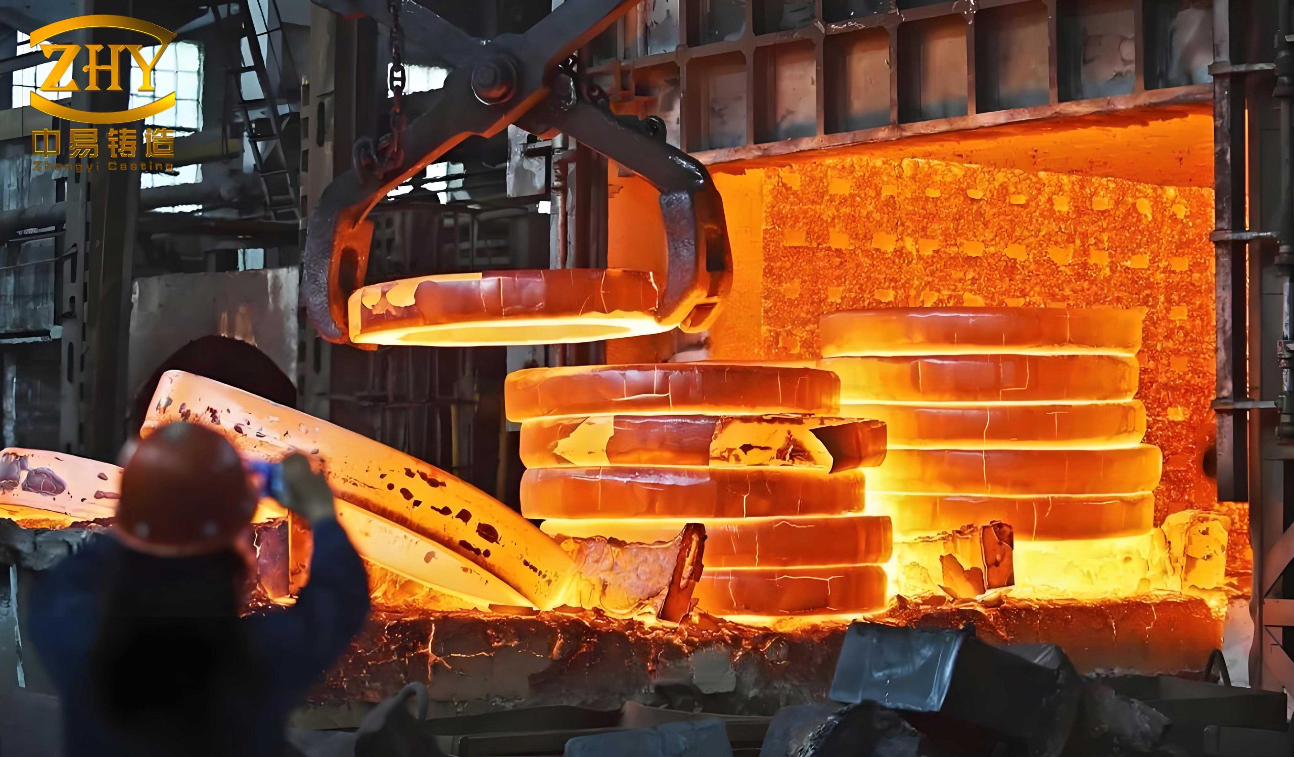
The image above illustrates a typical manifestation of heat treatment defects, such as cracking or distortion, often stemming from uncontrolled thermal gradients or pre-existing casting flaws. This visual underscores the critical need for the precise control systems we describe.
2. Microcomputer Control System for Casting Heat Treatment Furnaces
While casting automation sets the stage, the heat treatment process is where the metallurgical properties are finalized. Ineffective furnace control is a primary source of heat treatment defects. We developed a robust microcomputer-based control system specifically for electrical resistance heat treatment furnaces used for castings. The system’s goal is to enforce exact temperature-time profiles, thereby minimizing defects like soft spots, excessive grain growth, or transformation-induced stresses.
2.1 System Architecture and Functionality
The system is a hierarchical structure comprising a PC-based industrial computer (IPC) as the master, communicating with lower-level single-chip microcomputer units acting as regulators and data acquisition modules. The block diagram of the system is conceptually represented by the following data flow.
System Block Diagram Logic:
IPC (Master) ↔ Serial Communication Link ↔ [Regulator Units & Data Acquisition Units] ↔ Sensors/Actuators on Furnace Zones.
The furnace is treated as a Multi-Input, Multi-Output (MIMO) system with significant inertia and nonlinearity. The primary inputs are the control signals (0-10mA) to Silicon Controlled Rectifier (SCR) power regulators for each of the five furnace zones, and the outputs are the temperature readings from those zones. The core functions integral to preventing heat treatment defects include:
- Real-time display of temperature distribution curves across the furnace.
- Real-time display of zone temperatures and control current signals.
- Precise real-time temperature control for each zone.
- Real-time system model identification; bumpless auto/manual switching; online, bumpless switching of PID algorithms.
- Automatic fault-driven switch to manual mode, with audio-visual alarms for limit breaches.
This comprehensive monitoring and control is essential because uneven temperature distribution is a direct cause of heat treatment defects such as distortion and residual stress.
2.2 Software Architecture and Numerical Processing
The software is bifurcated into the IPC master software and the firmware for the regulator/data acquisition units. A key design philosophy was modularity and table-driven configuration to allow flexible, online adjustments—a necessity for optimizing processes to avoid heat treatment defects.
Master Software (IPC): Developed using a mix of C and assembly language, it operates as an interrupt-driven service. The main logic flow handles clock interrupts for timing and communication interrupts for data exchange with subordinate units. It manages:
- Communication protocols.
- Real-time clock management.
- Conversion of Analog-to-Digital (A/D) readings to engineering units (e.g., °C).
- Display of process flow diagrams, setpoints, and A/D calibration signals.
- Data logging of heating profiles.
- Alarm activation.
- A human-machine interface (HMI) for online configuration, parameter setting, and modification of the regulator’s control strategies.
Regulator/Data Acquisition Firmware: This software handles:
- System initialization and management.
- Self-diagnostics and power-loss protection.
- Signal sampling and digital filtering (e.g., median filter, moving average filter).
- Execution of control algorithms.
- Output signal generation and communication processing.
All numerical operations use a custom 3-byte floating-point format for high resolution and range, critical for accurate PID calculations to prevent control deviations that cause heat treatment defects. The format is:
Floating-Point Format:
Byte 1: Tail (Mantissa) Sign bit (b7) and 7 bits of mantissa MSB.
Byte 2: Mantissa LSB.
Byte 3: Exponent Sign bit (b7) and 7-bit exponent value.
This allows a representation range of approximately $$ \pm 0.5 \times 2^{127} \approx \pm 8.5 \times 10^{37} $$ with a resolution of about $$ 0.25 \times 2^{-127} \approx 1 \times 10^{-37} $$.
Basic arithmetic subroutines (addition, subtraction, multiplication, division, square root) and conversions between fixed-point and this floating-point format were implemented. The entire control strategy—from sampling rate and filter type to the control algorithm and its parameters—is defined by configuration tables populated and modifiable from the IPC. This table-driven approach is summarized below.
| Configuration Table Element | Description | Impact on Heat Treatment Defects |
|---|---|---|
| Sampling Period (θ) | Time interval between control updates. | Too slow: poor disturbance rejection; Too fast: system noise amplification. Both can lead to temperature overshoot/undershoot, causing heat treatment defects. |
| Filter Type | e.g., Median, Moving Average. | Reduces sensor noise, preventing erroneous control actions that create thermal instability and defects. |
| Control Algorithm | e.g., PID, PID with derivative filter. | Directly determines temperature tracking accuracy. Poor tuning results in profile deviation, a primary source of heat treatment defects. |
| PID Parameters (K₁, T₁, T₂, r) | Proportional gain, integral time, derivative time, derivative gain factor. | Optimal values are critical for stable, responsive control without oscillation, ensuring uniform microstructure and avoiding defects. |
2.3 Control Algorithm: Incremental PID for a Multi-Zone Furnace
The core challenge is controlling a high-inertia, coupled MIMO system. We employed an incremental PID algorithm with a derivative filter to handle noise. The discrete-time algorithm executed in the regulators is given by:
$$ u(k) = u_2(k-1) + K_1 \left(1 + \frac{\theta}{T_1}\right) \left[ \frac{rT_2}{rT_2 + \theta} D(k-1) + \frac{T_2 + \theta}{rT_2 + \theta} e(k) – \frac{T_2}{rT_2 + \theta} e(k-1) \right] $$
Where:
• \( u(k) \): Control output at sample \( k \).
• \( u_2(k-1) \): Previous integral output (accumulated).
• \( K_1 \): Proportional gain.
• \( \theta \): Control sampling period.
• \( T_1 \): Integral time constant.
• \( r \): Derivative gain coefficient (filtering factor).
• \( T_2 \): Derivative time constant.
• \( D(k-1) \): Previous derivative output.
• \( e(k) \): Current temperature error (setpoint – measurement).
• \( e(k-1) \): Previous temperature error.
This algorithm is applied independently to each zone, but the coupling between zones (due to thermal radiation and conduction) means that de-tuned controllers can cause zone-to-zone interference, leading to spatial temperature gradients and hence heat treatment defects. The derivative filter term (via \( r \)) is crucial for mitigating measurement noise, which if acted upon, could cause unnecessary power fluctuations and thermal instability—another precursor to defects.
The performance of this control law in minimizing temperature deviation is key to preventing heat treatment defects. The allowable temperature tolerance directly correlates with defect probability. We can model the relationship between temperature uniformity and the likelihood of a specific defect, like excessive growth of brittle phases, using a simplified probabilistic function:
$$ P_{defect} = 1 – \exp\left(-\alpha \cdot \sigma_T^2\right) $$
Where \( P_{defect} \) is the probability of encountering a heat treatment defect related to temperature non-uniformity, \( \sigma_T^2 \) is the variance of temperature across the workpiece or over time, and \( \alpha \) is a material-process specific constant. This underscores why our control system aims for a tight band of ±2°C.
3. Synergistic Impact on Defect Reduction and Process Optimization
The integration of automated casting and digitally controlled heat treatment creates a synergistic effect on quality. The benefits documented from our implementation are quantifiable and directly address the root causes of heat treatment defects.
| Performance Metric | Improvement Achieved | Direct Impact on Heat Treatment Defects |
|---|---|---|
| Casting Scrap Rate Reduction | 10–15 percentage points | Fewer flawed castings entering the furnace reduces the population susceptible to amplification of flaws into critical heat treatment defects. |
| Mold Life Increase | 20–30% | Longer mold life ensures consistent casting geometry and cooling rates, leading to more uniform initial microstructure for heat treatment, reducing the risk of defects. |
| Personnel Reduction vs. Manual | 30–50% | Reduces human variability, a significant source of inconsistent practices that induce heat treatment defects. |
| Furnace Temperature Control Precision | ±2°C maintained | Directly minimizes thermal gradients, preventing defects like distortion, soft spots, and uneven transformation products. |
The furnace control system’s ability to maintain the setpoint profile with a precision of ±2°C is perhaps the most significant factor. Many heat treatment defects are governed by Arrhenius-type kinetics, where the rate of a detrimental process (e.g., undesirable phase formation) is exponentially dependent on temperature. Small, sustained deviations can thus have large effects. The control system’s performance can be analyzed by considering the integral of absolute error (IAE) over a treatment cycle:
$$ IAE = \int_{0}^{t_{cycle}} |e(t)| dt $$
where \( e(t) \) is the temperature error. A low IAE, as achieved by our PID system, correlates directly with reduced incidence of heat treatment defects. Furthermore, the system’s real-time model identification allows for adaptive tuning, which is crucial when furnace characteristics change with wear or different load configurations, preemptively addressing potential sources of defects.
4. Mathematical Modeling of Defect Formation and Control Response
To further justify our approach, we can formalize the relationship between process parameters and heat treatment defects. Let us consider a common defect: quench cracking. Its propensity can be related to the thermal stress (\( \sigma_{th} \)) generated during heating or cooling, which is a function of the temperature gradient (\( \nabla T \)) and material properties.
$$ \sigma_{th} \propto E \cdot \alpha \cdot |\nabla T| $$
Where \( E \) is Young’s modulus and \( \alpha \) is the coefficient of thermal expansion. Our control system minimizes \( \nabla T \) by ensuring uniform zone temperatures, thus reducing \( \sigma_{th} \) and the risk of this heat treatment defect.
For defects related to phase transformation kinetics, such as incomplete austenitization in steels or inadequate solution treatment in aluminum alloys, the process can be modeled. The fraction of transformation \( f \) is often described by the Johnson-Mehl-Avrami-Kolmogorov (JMAK) equation:
$$ f(t) = 1 – \exp\left(-(k t)^n\right) $$
where the rate constant \( k \) is temperature-dependent: \( k = k_0 \exp\left(-\frac{Q}{RT}\right) \), with \( Q \) as activation energy, \( R \) the gas constant, and \( T \) the absolute temperature. Inconsistent temperature \( T \) leads to non-uniform transformation fraction \( f \) across the workpiece, a direct heat treatment defect. Our control system stabilizes \( T \), promoting uniform \( f \).
The PID controller’s role is to reject disturbances \( d(t) \) (e.g., load changes, ambient variations) that affect furnace temperature. The closed-loop transfer function for a simplified zone model \( G(s) = \frac{K}{\tau s + 1} e^{-Ls} \) (a first-order plus dead-time model) under PID control \( C(s) = K_p + \frac{K_i}{s} + K_d s \) determines the error response. Minimizing the error spectrum across the frequency range of typical disturbances is essential to prevent the periodic temperature variations that can cause rhythmic heat treatment defects like banding.
5. Conclusion and Forward Path
Our development and implementation of an automated casting cell coupled with a sophisticated microcomputer-controlled heat treatment furnace demonstrate a holistic approach to modern foundry operations. The central thread throughout this discussion has been the identification, understanding, and mitigation of heat treatment defects. By automating the ladling and extraction processes, we ensure casting consistency. By applying advanced digital control with robust PID algorithms and flexible software architecture to the heat treatment furnace, we enforce precise thermal profiles.
The results are clear: a dramatic reduction in scrap rates, improved mechanical properties, and enhanced production efficiency. However, the pursuit of zero heat treatment defects is ongoing. The observed performance gap with international counterparts, often attributed to component quality in hydraulics and electronics, highlights an area for improvement. Our future work will focus on integrating higher-fidelity sensors, employing more advanced decoupling control strategies like Model Predictive Control (MPC) for the MIMO furnace system, and selectively upgrading critical components. These steps will further tighten process windows, adapt to more complex alloy specifications, and virtually eliminate the categories of heat treatment defects that currently challenge the industry. The mathematical frameworks and control principles detailed here provide a foundation for this continued evolution towards fully optimized, defect-aware manufacturing systems.