
In the field of internal combustion engine design and reliability engineering, the crankshaft stands as a critical and highly stressed component. Its primary function is to convert the reciprocating linear motion of the pistons into rotational motion, a process that subjects it to complex, multi-axial cyclic loading conditions including bending, torsion, and vibration. Consequently, crankshaft failure is a significant concern, often leading to catastrophic engine seizure and substantial economic loss. The material of choice for many medium-duty applications is spheroidal graphite cast iron, particularly grades like QT700-2, which offers an excellent balance of tensile strength, castability, wear resistance, and damping capacity. However, despite its favorable properties, failures do occur. This article presents a first-person, detailed investigation into the failure of a QT700-2 spheroidal graphite cast iron crankshaft, employing a multi-faceted analytical approach to determine the root cause and propose mitigating solutions.
The subject of this analysis was a spheroidal graphite cast iron crankshaft, specified as QT700-2, which fractured during a road test durability trial. The fracture occurred at the fourth connecting rod journal. Initial visual inspection confirmed that the failure originated from the fillet radius region of this journal, a classic high-stress concentration zone. There were no signs of external impact damage or abnormal wear on the adjacent surfaces, directing the focus towards material integrity, manufacturing processes, and loading conditions as potential culprits. The investigation protocol was designed to systematically eliminate or confirm potential failure modes through macroscopic and microscopic fractography, metallurgical examination, chemical analysis, residual stress measurement, and mechanical property verification.
Macroscopic and Microscopic Fractography
The fracture surface exhibited clear classic fatigue characteristics. Multiple crack initiation sites were observed along the edge of the rolled fillet at the fourth journal. These initiation points formed distinct ratchet marks or steps, indicative of cracks starting independently at several locations on the surface before linking up. The fracture surface showed a smooth, progressive crack growth region with faint beach marks, radiating from the initiation zones, followed by a final, rougher fast fracture area. The presence of multiple initiation sites immediately suggests a high applied stress or a reduced local fatigue strength at the surface.
Scanning Electron Microscopy (SEM) examination of the crack initiation zones revealed a quasi-cleavage fracture morphology. Notably, no pre-existing casting defects such as shrinkage porosity, slag inclusions, or large clusters of degenerate graphite were found at the origins. This rules out major material quality issues as the primary driver. The fatigue crack propagation zone clearly displayed micro-scale striations, the hallmark of cyclic crack advance. The transition to the final overload zone showed a more ductile dimpled rupture mixed with cleavage facets, common in spheroidal graphite cast iron under monotonic loading.
A critical observation was made on the surface condition of the rolled fillet. The fillet root itself appeared smooth, likely from the rolling process which induces plastic deformation. However, at the very edge of the fillet, where it meets the journal’s cylindrical surface, machining marks (tool marks) oriented circumferentially were still visible. This was true for both the failed fourth journal and an unfailed first journal examined for comparison. This suggests that the rolling process did not completely work and smooth this sharp transitional edge, leaving a potential micro-notch. Stress concentration factors for such geometries can be significantly high. The formula for the theoretical stress concentration factor \( K_t \) for a rounded notch in torsion is a function of the geometry:
$$
K_t = 1 + \sqrt{\frac{a}{r}}
$$
where \( a \) is a depth parameter related to the notch and \( r \) is the root radius. A sharp transition effectively reduces \( r \), leading to a higher \( K_t \), thus amplifying the local stress.
Metallurgical and Material Property Investigation
A comprehensive analysis of the material’s constitution and condition was undertaken. The results are summarized in the following tables.
| Element | Standard for QT700-2 | Measured Value |
|---|---|---|
| Carbon (C) | 3.60 – 3.85 | 3.24 |
| Silicon (Si) | 1.90 – 2.60 | 2.37 |
| Manganese (Mn) | 0.20 – 0.70 | 0.40 |
| Sulfur (S) | ≤ 0.030 | 0.0071 |
| Phosphorus (P) | ≤ 0.050 | 0.026 |
The chemical analysis showed that the carbon content was below the specified lower limit. In spheroidal graphite cast iron, carbon exists primarily in two forms: as graphite spheroids and combined carbon in the matrix (e.g., in pearlite). A lower total carbon could affect the graphite nodule count and size distribution, potentially influencing mechanical properties. However, other key elements were within acceptable ranges.
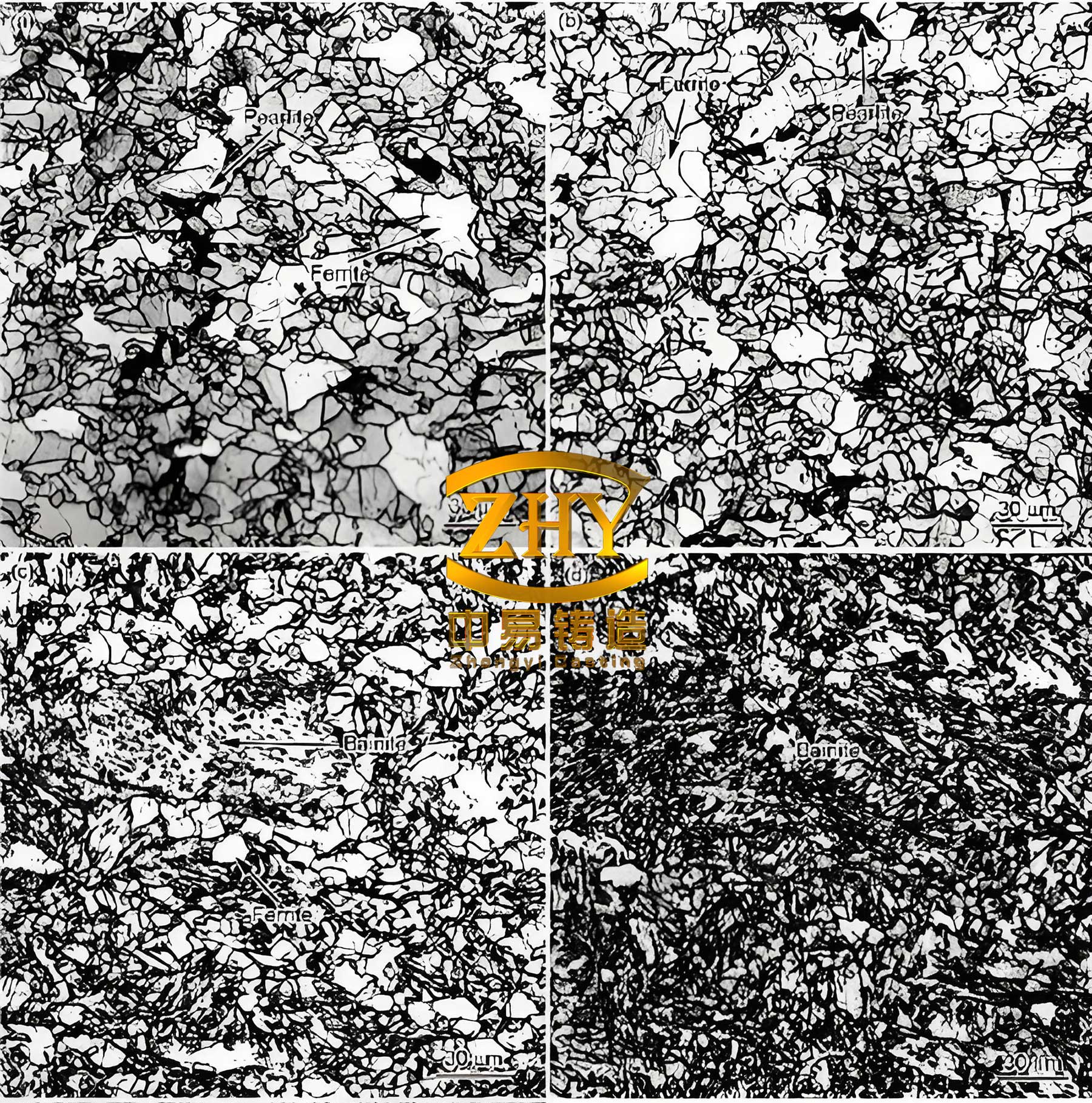
| Location | Graphite Morphology | Matrix Structure | Comments |
|---|---|---|---|
| Fillet of 4th Journal | Spheroidal, Nodularity >90% (Grade 1), Size ~3-6 μm (Grade 6) | Pearlite (>98%) with minor ferrite. Carbides ~0.5%. Phosphide eutectic ~1%. | No significant plastically deformed layer from rolling was evident at the surface. |
| Core of 4th Journal | Spheroidal, Nodularity >90% | Pearlite (>98%) with minor ferrite. Carbides ~0.5%. Phosphide eutectic ~1%. | Uniform microstructure. |
| Fillet of 1st Journal | Spheroidal, Nodularity >90% (Grade 1), Size ~3-6 μm (Grade 6) | Pearlite (>98%) with minor ferrite. Carbides ~0.5%. Phosphide eutectic ~1%. | Similar to 4th journal. No obvious deformed layer. |
The microstructure was generally acceptable for QT700-2 spheroidal graphite cast iron, characterized by a predominantly pearlitic matrix which provides high strength. The graphite was well-spheroidized. However, the presence of minor carbides and phosphide eutectic, while within typical limits, can act as local brittle phases, potentially initiating micro-cracks under high stress. The absence of a pronounced work-hardened layer from the fillet rolling operation was surprising and will be discussed later.
The case hardening depth (induction hardening) on the journals was also examined. The hardened layer profile was inconsistent. On the fourth journal, the unhardened zone width varied from 4.5 mm to 5.5 mm, with the hardened depth ranging from 1.5 mm at the center to 2.0 mm at the sides. This non-uniformity can create gradients in hardness and residual stress, potentially leading to undesirable stress distributions under load.
| Property | Location / Sample | Measured Value | QT700-2 Requirement |
|---|---|---|---|
| Hardness (Core, HB) | 4th Journal Core | 268, 270, 275 | 240 – 320 HB |
| Hardness (Core, HB) | 1st Journal Core | 291, 280, 280 | |
| Hardness (Surface, HRC) | 4th Journal Fillet | 56.0, 55.5, 55.5 | 45 – 60 HRC |
| Hardness (Surface, HRC) | 1st Journal Fillet | 55.5, 55.5, 54.5 | |
| Tensile Strength (MPa) | Sample 1# | 970 | ≥ 770 |
| Tensile Strength (MPa) | Sample 2# | 999 | |
| 0.2% Proof Strength (MPa) | Sample 1# | 589 | ≥ 480 |
| 0.2% Proof Strength (MPa) | Sample 2# | 617 | |
| Elongation (%) | Sample 1# | 7.5 | ≥ 3 |
| Elongation (%) | Sample 2# | 8.0 |
The bulk mechanical properties, including tensile strength, yield strength, elongation, and hardness (both core and surface), comfortably exceeded the minimum requirements for QT700-2 spheroidal graphite cast iron. This confirms that the base material was not inherently weak.
Residual Stress Analysis and Its Critical Role
Surface residual stress is a paramount factor influencing fatigue performance, especially in components like crankshafts. Compressive residual stresses are highly beneficial as they effectively lower the mean stress of the fatigue cycle, thereby retarding crack initiation and growth. The rolling process is specifically applied to crankshaft fillets to induce deep compressive stresses. X-ray diffraction measurements were taken on the fillets of the unfailed first journal (Point A) and on both sides of the failed fourth journal (Points B and C, with C being on the fracture face where stress may have relaxed).
| Measurement Point | Residual Stress (σres) | Comment |
|---|---|---|
| A (1st Journal Fillet) | -407.6 ± 22.8 | High compressive stress, as expected from effective rolling. |
| B (4th Journal Fillet, unfractured side) | -333.8 ± 24.7 | Compressive, but significantly lower magnitude than Point A. |
| C (4th Journal Fillet, fractured side) | -63.3 ± 8.5 | Very low compressive stress, likely due to relaxation after fracture. |
The data reveals a stark discrepancy. The residual compressive stress at the fillet of the intact first journal was substantial (-408 MPa), which is desirable. However, on the unfractured side of the failed fourth journal, the compressive stress was approximately 18% lower (-334 MPa). This indicates a possible inconsistency in the rolling process parameters (force, feed rate, roller alignment) or a local material condition that affected the efficacy of strain hardening. The modified Goodman relation for mean stress effect illustrates the importance of compressive residual stress (σres):
$$
\sigma_a = \sigma_{fat} \left(1 – \frac{\sigma_m + \sigma_{res}}{\sigma_u}\right)
$$
where \( \sigma_a \) is the allowable alternating stress amplitude, \( \sigma_{fat} \) is the fully reversed fatigue strength, \( \sigma_m \) is the applied mean stress, \( \sigma_{res} \) is the residual stress (negative for compression), and \( \sigma_u \) is the ultimate tensile strength. A lower compressive \( \sigma_{res} \) directly reduces the allowable \( \sigma_a \), making the component more susceptible to fatigue.
Synthesis and Root Cause Analysis
Piecing together the evidence, the failure mechanism becomes clear. The spheroidal graphite cast iron crankshaft failed due to multi-origin torsional-bending fatigue. The primary root cause was not a gross material defect, but a combination of factors that critically lowered the fatigue strength at a specific stress raiser.
- Stress Concentration at a Micro-Notch: The primary initiator was the sharp, incompletely worked edge between the rolled fillet and the journal surface. The residual machining marks acted as micro-notches, creating a locally elevated stress concentration factor \( K_t \). This is the site where all fatigue cracks nucleated.
- Insufficient and Inconsistent Beneficial Residual Stress: The fillet rolling process, intended to impart high compressive stresses, was inconsistent. The fourth journal had a measurably lower surface compressive stress compared to the first journal. This reduced the component’s resistance to crack initiation from the micro-notches. The relationship between the applied shear stress amplitude \( \tau_a \), the fatigue limit in shear \( \tau_e \), and the stress concentration is given by:
$$
\tau_a \cdot K_f \geq \tau_e
$$
where \( K_f \) is the fatigue strength reduction factor (slightly less than \( K_t \) for ductile materials). A high \( K_f \) from the micro-notch and a potentially lower effective \( \tau_e \) due to reduced compressive stress made this inequality true, leading to crack initiation.
- High Applied Cyclic Loads: The presence of multiple crack initiation sites and ratchet marks is a classic indicator of high applied stress amplitudes. The torsional loads during the road test, potentially due to engine mapping, drivetrain dynamics, or specific driving conditions, were significant enough to drive crack initiation at multiple weak points along the fillet edge.
- Contributing Factors: The non-uniform induction hardening pattern and the slightly off-specification carbon content may have contributed to a less than optimal microstructure and stress state, but were not the dominant causes. The bulk material properties were satisfactory.
The crack initiated in Mode II (sliding shear) due to the dominant torsional loading, transitioning to mixed-mode growth as it propagated. The crack growth life \( N_g \) can be described by the Paris Law for the propagating stage:
$$
\frac{da}{dN} = C (\Delta K)^m
$$
where \( a \) is crack length, \( N \) is cycles, \( C \) and \( m \) are material constants, and \( \Delta K \) is the stress intensity factor range. Once initiated, the crack propagated through the section until the remaining ligament could no longer support the load, resulting in final ductile-overload fracture.
Conclusions and Engineering Recommendations
The failure of this QT700-2 spheroidal graphite cast iron crankshaft was a classic case of fatigue driven by a synergistic combination of a local stress concentrator, suboptimal surface enhancement, and high operational loads. To prevent recurrence and enhance the fatigue durability of spheroidal graphite cast iron crankshafts, the following improvements are recommended:
| Identified Deficiency | Proposed Corrective Action | Expected Benefit |
|---|---|---|
| Micro-notch at fillet/journal edge from incomplete rolling. | Modify the rolling tool profile and process parameters to ensure full plastic working of the entire fillet region, including the transitional edge. Implement 100% visual or profilometer inspection of the rolled fillet geometry. | Eliminate the primary stress concentrator, significantly reducing \( K_t \). |
| Inconsistent and low magnitude of compressive residual stress from fillet rolling. | Standardize and tightly control the rolling process (force, speed, number of passes, roller condition). Implement periodic verification using X-ray diffraction or ultrasonic stress measurement on sample parts or designated journal positions. | Ensure a consistently high and deep compressive residual stress field, maximizing the mean stress benefit in the modified Goodman diagram. |
| Non-uniform induction hardening pattern. | Review and optimize the induction heating coil design and quenching parameters to achieve a symmetrical and consistent hardened case depth and profile around the journal circumference. | Promote a uniform distribution of hardness and transformation-induced stresses, avoiding soft spots that become weak links. |
| Potential for high operational torsional loads. | Review engine/vehicle testing protocols and consider the installation of a torsional vibration damper (if not present) or evaluate its effectiveness. Analyze engine calibration data from the failed test. | Reduce the applied alternating stress amplitude \( \tau_a \), increasing the safety margin against fatigue. |
| General enhancement. | As a supplementary process, consider applying shot peening or ultrasonic nanocrystal surface modification (UNSM) after rolling. These processes can further enhance surface compressive stresses, refine the near-surface microstructure, and smooth micro-irregularities. | Provide an additional layer of protection against fatigue initiation, particularly from intrinsic microstructural features like carbides or graphite nodules intersecting the surface. |
In conclusion, the reliable performance of spheroidal graphite cast iron components like crankshafts under severe cyclic loading is highly dependent on the meticulous control of manufacturing processes that govern surface integrity. While the inherent properties of QT700-2 spheroidal graphite cast iron provide a strong foundation, it is the synergistic combination of optimal geometry, high and consistent compressive residual stresses, and a sound microstructure that unlocks its full fatigue potential. This investigation underscores the critical importance of a holistic quality assurance strategy that goes beyond checking bulk chemical and mechanical properties, delving into the realm of surface metrology and subsurface stress state control.