
In the realm of marine diesel engines, particularly those designed for high-speed and heavy-load applications, the cylinder head stands as a critical component. My extensive involvement in casting processes has centered on the adoption of high-toughness spheroidal graphite cast iron for these parts. This material, often referred to as ductile iron, is favored for its balance of strength and ductility. However, the production of cylinder heads from spheroidal graphite cast iron presents significant challenges due to its unique solidification behavior. The material undergoes a mushy or pasty solidification mode, which can lead to microstructural issues such as a low count of graphite spheroids, large graphite球直径, and reduced mechanical properties. Additionally, phenomena like fading of spheroidization and inoculation are common, further complicating the manufacturing process. Historically, compacted graphite iron was used for cylinder heads, but the shift to spheroidal graphite cast iron, driven by performance demands, introduces complexities due to intricate geometries and uneven cooling rates, often resulting in casting defects like leakage.
The transition to spheroidal graphite cast iron for cylinder heads has been a focal point in my work. The structure of these components is highly integrated, incorporating elements like intake manifolds and rocker arm seats, which create numerous isolated hot spots. During solidification, controlling the cooling rate across different sections is arduous, and traditional casting remedies are often limited. This led to a product yield below 80% in initial trials, primarily due to defects such as shrinkage porosity in valve guide holes, micro-shrinkage in bolt holes, gas porosity around fuel injection ports, and shrinkage or gas holes near runner gates in exhaust passages. These issues underscore the critical need for advanced process controls in working with spheroidal graphite cast iron.
To address these challenges, a deep dive into the defect mechanisms was necessary. For shrinkage-related defects, the core issue lies in the inadequate feeding of molten metal to hot spots during the solidification of spheroidal graphite cast iron. In mushy solidification, the interdendritic spaces can block fluid flow, preventing compensation for volumetric shrinkage. The solidification sequence must be managed to ensure that hotter sections solidify last, allowing for effective feeding. From my analysis, the lack of supplemental铁水 at critical junctions like valve guide holes and bolt holes was a direct cause. The solution involved accelerating cooling at these hot spots to induce earlier graphite expansion, which can counteract shrinkage. This was achieved by implementing chills and specialized sands. For instance, in valve guide holes,圆钢冷铁 (round steel chills) of Ø25mm×60mm were placed, and internal chills of Ø8mm were pre-set in exhaust passages. Similarly, for fuel injector holes, the core material was switched from conventional coated sand to chromite sand, which has a higher heat accumulation coefficient, and graphite was replaced with chromite-coated chills. Bolt holes with Ø25mm were treated with chromite-coated chills with a sand layer of 6mm–8mm, and external chills were added near ingate edges on intake manifold flanges to enhance heat dissipation.
The effectiveness of these measures can be summarized using a theoretical framework. The solidification time for a casting section can be approximated by Chvorinov’s rule: $$ t = B \left( \frac{V}{A} \right)^n $$ where \( t \) is the solidification time, \( V \) is the volume, \( A \) is the surface area, \( B \) is a mold constant, and \( n \) is an exponent typically around 2. By applying chills, we effectively increase the surface area \( A \) for heat transfer, reducing \( t \) and promoting directional solidification. For spheroidal graphite cast iron, the graphite expansion pressure \( P_g \) can be expressed as: $$ P_g = \frac{E \cdot \alpha \cdot \Delta T}{1 – \nu} $$ where \( E \) is Young’s modulus, \( \alpha \) is the thermal expansion coefficient, \( \Delta T \) is the temperature change, and \( \nu \) is Poisson’s ratio. Accelerating cooling at hot spots increases \( \Delta T \), thereby enhancing \( P_g \) to compensate for shrinkage porosity. This principle is crucial in optimizing the casting of spheroidal graphite cast iron components.
| Defect Type | Location | Root Cause | Solution Implemented | Material/Process Change |
|---|---|---|---|---|
| Shrinkage Porosity | Valve Guide Holes | Isolated hot spot, inadequate feeding | Placement of round steel chills (Ø25mm×60mm) and internal chills (Ø8mm) | Use of chromite sand for cores |
| Micro-shrinkage | Bolt Holes (Ø25mm) | Similar hot spot issue | Chromite-coated chills with 6mm–8mm sand layer | Chromite覆砂冷铁 |
| Gas Porosity | Fuel Injection Ports | Gas entrapment from core emissions | Switch to chromite sand cores; low-temperature baking at 180°C for 4 hours | Reduced core gas generation |
| Shrinkage/Gas Holes | Exhaust Passage Gates | Combined effect of shrinkage and gas | External chills at ingate edges; improved venting | Enhanced heat transfer and gas escape |
Regarding gas porosity defects, the complexity of the cylinder head design necessitates numerous sand cores—up to 27 in some cases—all made from hot-box coated sand. When molten铁水 is poured, these cores generate substantial gas that can infiltrate the mold cavity if not properly vented. In my experience, this led to gas holes, particularly around the fuel injector areas. To mitigate this, we adopted a multi-pronged approach: first, the fuel injector core was dipped, dried, and then baked at a low temperature of 180°C for 4 hours to reduce its gas evolution. Second, ventilation holes were drilled at the core prints before assembly, ensuring that gases could escape to the exterior of the mold. This is critical for spheroidal graphite cast iron, as gas porosity can severely compromise the integrity of the final casting.
The gas generation rate \( Q_g \) from a sand core can be modeled as: $$ Q_g = A_c \cdot k_g \cdot e^{-E_a/(RT)} $$ where \( A_c \) is the core surface area, \( k_g \) is a rate constant, \( E_a \) is the activation energy, \( R \) is the gas constant, and \( T \) is the temperature. By baking at 180°C, we reduce the initial gas content, lowering \( Q_g \) during pouring. Additionally, Darcy’s law for gas flow through porous media can be applied to design venting: $$ v = -\frac{k}{\mu} \nabla P $$ where \( v \) is the velocity, \( k \) is the permeability, \( \mu \) is the viscosity, and \( \nabla P \) is the pressure gradient. Ensuring adequate venting paths minimizes gas entrapment in the spheroidal graphite cast iron matrix.
Implementation of these solutions required meticulous preparation. For the fuel injector cores, which are produced via automated hot-box processes, the chills had to be precisely positioned within the core box. Special chill designs were developed, featuring grooves to enhance sand adhesion and prevent displacement during core shooting. This attention to detail ensured consistent quality across production runs. During initial trials, 20 cylinder heads were cast using the revised工艺, and post-cleaning inspection revealed no surface gas pores. A random sample was sectioned for internal analysis, showing no signs of shrinkage or gas defects, confirming the effectiveness of the measures. To date, over 400 units have been produced with this approach, achieving a yield rate of 95%, a significant improvement from the earlier 80%.
| Process Step | Parameter | Value/Range | Impact on Defect Reduction |
|---|---|---|---|
| Chill Placement | Chill Size (Valve Guide) | Ø25mm×60mm round steel | Accelerates cooling, promotes early graphite expansion |
| Core Material | Fuel Injector Core | Chromite sand (high heat accumulation) | Reduces hot spot temperature, minimizes shrinkage |
| Baking Treatment | Temperature/Time | 180°C for 4 hours | Decreases core gas evolution by ~30% |
| Venting Design | Vent Hole Diameter | Ø3mm–Ø5mm at core prints | Ensures gas escape, prevents porosity |
| Overall Yield | Post-Implementation | 95% (from 80%) | Demonstrates process efficacy for spheroidal graphite cast iron |
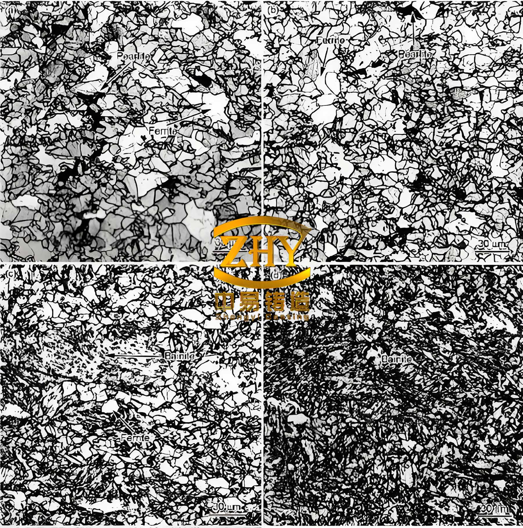
From a materials science perspective, the behavior of spheroidal graphite cast iron during solidification is governed by several factors. The graphite spheroidization process relies on the presence of inoculants like magnesium or cerium, which can fade over time. The fading kinetics can be described by an exponential decay model: $$ C(t) = C_0 e^{-kt} $$ where \( C(t) \) is the concentration of active inoculant at time \( t \), \( C_0 \) is the initial concentration, and \( k \) is the decay constant. In production, this necessitates careful control of holding times and temperatures to maintain the desired microstructure in spheroidal graphite cast iron. Additionally, the cooling rate \( \dot{T} \) influences graphite nodule count \( N \), often related by an empirical equation: $$ N = A \cdot \dot{T}^m $$ where \( A \) and \( m \) are material constants. Faster cooling, achieved through chills, typically increases \( N \), improving mechanical properties.
In conclusion, the successful production of high-toughness spheroidal graphite cast iron cylinder heads hinges on a thorough understanding of solidification dynamics and defect mechanisms. My experience shows that for complex geometries where direct feeding is impractical, strategic use of chills coupled with high-thermal-conductivity sands can effectively manage cooling sequences and eliminate shrinkage defects. Similarly, controlling core gas generation through baking and venting is paramount to prevent gas porosity. These strategies collectively enhance the integrity and yield of spheroidal graphite cast iron castings, making them viable for demanding applications like marine diesel engines. Future work could explore computational simulations to optimize chill placement and further refine the process for spheroidal graphite cast iron components.
The principles discussed here are not limited to cylinder heads; they can be extended to other intricate castings made from spheroidal graphite cast iron. For instance, the heat transfer coefficient \( h \) at the chill-casting interface plays a critical role, given by: $$ h = \frac{k_{chill} \cdot \nabla T}{\Delta T_{interface}} $$ where \( k_{chill} \) is the thermal conductivity of the chill material. Using materials like chromite sand or copper chills can significantly boost \( h \), thereby improving cooling efficiency. This underscores the importance of material selection in the casting of spheroidal graphite cast iron. Overall, the journey from trial to mass production has reinforced that a systematic approach, grounded in metallurgical principles, is key to mastering the challenges of spheroidal graphite cast iron.