
The development of a robust and efficient manufacturing process for safety-critical automotive components represents a significant engineering challenge. My focus here is on the process development for a vacuum wheel rim, a vital safety component in commercial and engineering vehicles. Made from ductile spheroidal graphite cast iron (grade QT450-15), this part exemplifies the demanding requirements of modern transportation: it must possess excellent mechanical properties, high dimensional accuracy, particularly in wall thickness, and superior surface finish, all while being produced in a cost-effective manner. The conventional casting methods struggled with the part’s complex geometry, specifically the peripheral annular groove, leading to compromises in quality, cost, and efficiency. This narrative details my first-hand experience and rationale behind selecting and developing a Lost Foam Casting (LFC) process as the optimal solution, overcoming these limitations and unlocking new levels of performance and economy.
The structural complexity of the vacuum wheel rim is its defining characteristic. As a large-diameter, thin-walled casting with a nominal weight of 60 kg and an average wall thickness of 10–15 mm, its design includes a challenging peripheral groove and numerous functional holes on the web (for ventilation and mounting). Traditional green sand or resin sand molding using two-part cope and drag molds cannot directly form this external groove. The only alternative within those processes is to incorporate a massive, ring-shaped sand core. This approach introduces several critical drawbacks: it degrades surface finish at the core-print junctions, increases production time and labor cost through core-setting operations, and most detrimentally, introduces the risk of core shift. This shift can lead to unacceptable variations in wall thickness—a potential point of failure under cyclic loading during vehicle operation. Therefore, the search for an alternative process was imperative. After thorough analysis, the Lost Foam Casting process emerged as the superior choice, primarily because it builds the mold cavity directly from a replica of the final part, thereby inherently accommodating complex geometries without cores, ensuring perfect wall thickness uniformity, and delivering an excellent as-cast surface.
Strategic Advantages of the Lost Foam Process for Spheroidal Graphite Iron
The decision to adopt LFC was driven by a clear set of strategic advantages tailored to the vacuum wheel rim’s needs. Beyond the general benefits of LFC, such as reduced cleaning and improved working environment, several factors were decisive for this specific spheroidal graphite cast iron component.
| Process | Wall Thickness Control | Surface Finish | Ability to Cast Holes | Tooling Cost & Lead Time | Process Complexity |
|---|---|---|---|---|---|
| Traditional Green Sand (with Core) | Poor (Risk of core shift) | Fair | Limited (requires machining) | Low-Moderate | Moderate |
| Resin Sand (with Core) | Better but not optimal | Good | Limited (requires machining) | Moderate-High | High |
| Lost Foam Casting | Excellent (No cores needed) | Very Good | Excellent (Near-net-shape) | Moderate (Pattern tooling) | Moderate (Controllable) |
Firstly, the process allows for exceptional near-net-shape capabilities. We designed the expanded polystyrene (EPS) pattern to incorporate the ventilation holes and the valve stem hole in their final as-cast dimensions. This ‘cast-to-size’ feature eliminates entire machining operations, saving on equipment capital and operational costs. The bolt mounting holes were also cast as pre-forms, significantly reducing the machining allowance and subsequent tool wear, which boosts machining efficiency. Secondly, the vacuum applied during mold filling is particularly beneficial for thin-section spheroidal graphite cast iron castings. The negative pressure enhances the metallostatic head, improving mold filling capability and reducing the risk of mistruns or cold shuts. More importantly, it promotes superior feeding during solidification. The pressure differential helps move liquid metal into micro-shrinkage regions, resulting in a denser, more sound microstructure, which is crucial for the fatigue performance of the wheel rim. The relationship between vacuum pressure, feeding efficiency, and internal soundness can be conceptually modeled. The pressure differential $\\Delta P$ aiding feeding can be expressed as a function of atmospheric pressure $P_{atm}$, system vacuum $P_{vac}$, and the head of metal $\\rho g h$:
$$\\Delta P_{feeding} = P_{atm} – P_{vac} + \\rho g h$$
where $\\rho$ is the density of the molten iron, $g$ is gravity, and $h$ is the effective metallostatic height. A higher $\\Delta P$ directly improves the ability to counteract shrinkage porosity.
Comprehensive Process Development and Implementation
The development journey involved meticulous attention to each step of the LFC process chain, acknowledging and solving challenges specific to this large, thin-walled pattern.
1. Pattern Production and Integrity Management
The first challenge was pattern fabrication. While CNC machining of EPS blocks is feasible for prototyping, for series production, custom aluminum tooling for steam-chest molding of EPS beads was developed. To counteract the inherent tendency of the large, open-ring structure to warp or distort, especially at the upper rim, we increased the base pattern density to a range of 26–32 g/L. A higher density foam provides greater strength and thermal degradation resistance during coating and handling. The relationship between foam density and key properties is summarized below:
| Density Range (g/L) | Pattern Strength | Dimensional Stability | Gas Evolution During Pour | Typical Application |
|---|---|---|---|---|
| 20-24 | Low | Poor (High distortion risk) | High | Simple, thick-section parts |
| 26-32 | High | Good (Controlled distortion) | Moderate | Complex, thin-walled parts (e.g., Wheel Rim) |
| >35 | Very High | Excellent | Lower | Precision components, high cost |
Furthermore, a proactive anti-distortion strategy was implemented. Before coating, we adhesively bonded reinforcement ribs in a cross pattern across the open diameter of the wheel rim pattern. These ribs, made from fiberglass strands, maintained the dimensional integrity of the pattern cluster through the coating, drying, and sand-filling stages, and are completely consumed during the pour.
2. Gating System Design and Cluster Assembly
Gating design in LFC must ensure smooth, progressive filling to avoid turbulent entrapment of pattern degradation products. For this top-poured wheel rim, a multiple ingate system was designed to distribute the metal flow evenly around the circumference. A central downsprue feeds into a horizontal runner ring, from which numerous tangential ingates connect to the rim’s upper section. This promotes a rapid but controlled fill. Additionally, 6 to 8 small blind risers/slag collectors were placed at the highest points of the mold cavity (on the top face of the pattern cluster) to collect first metal and any initial foam residue. The complete pattern cluster, with its gating and reinforcement, formed the negative of the eventual mold cavity.
3. Coating Application and Drying
The coating is the critical interface between the degrading foam and the advancing metal front. We selected a refractory, water-based coating with a base of silica flour and other additives to provide good permeability and strength. The coating must allow gaseous pyrolysis products to escape while preventing sand penetration. The cluster was dipped twice to achieve a uniform coating thickness of approximately 0.5-0.8 mm per layer. Drying was conducted carefully in a controlled dehumidification chamber at temperatures below 55°C for 8-10 hours per layer to prevent pattern distortion from rapid steam generation. The drying kinetics are crucial; insufficient drying leads to wet spots causing gas defects, while excessive heat warps the pattern. The coating’s permeability $K$ is a key parameter, ideally following a relationship that balances gas escape with metal pressure:
$$K \\propto \\frac{\\eta \\cdot L^2}{\\Delta P \\cdot t}$$
where $\\eta$ is the viscosity of the degrading foam gases, $L$ is the coating thickness, $\\Delta P$ is the pressure drop across the coating, and $t$ is time.
4. Sand Filling, Compaction, and Vacuum-Assisted Pouring
Unbonded, dry zircon sand was chosen for its excellent flowability, high thermal stability, and reusability. The coated cluster was placed in the flask, and sand was introduced while employing intermittent three-dimensional vibration to ensure dense, uniform packing around the complex geometry, especially in the internal cavities and the annular groove. After filling, a plastic film seals the flask top. The crucial step is the application of vacuum, typically maintained between 0.04 and 0.06 MPa (400-600 mbar below atmospheric). This vacuum consolidates the sand, imparting immediate mold strength, and is maintained during pouring and initial solidification. The vacuum serves multiple functions: it strengthens the unbonded mold, extracts foam pyrolysis gases through the coating and sand, and enhances the metallostatic pressure as previously described. The pouring temperature for the spheroidal graphite cast iron was carefully controlled within the range of 1,380–1,420°C to balance fluidity, pattern degradation rate, and thermal contraction.
5. Process Parameters and Optimization
Developing a stable process required optimizing several interdependent variables. Through iterative trials, we established a robust window for key parameters. The table below summarizes the finalized critical process parameters that yielded consistent, high-quality castings.
| Process Parameter | Target Range / Value | Influence on Casting Quality |
|---|---|---|
| EPS Pattern Density | 28 ± 2 g/L | Dictates pattern strength, dimensional stability, and gas load. |
| Coating Thickness (dry, per layer) | 0.6 ± 0.1 mm | Controls permeability, sand penetration resistance, and insulation. |
| Sand Type & AFS GFN | Zircon Sand, ~100 GFN | Provides high thermal conductivity and excellent flowability. |
| Mold Vacuum Level | 0.05 ± 0.01 MPa | Determines mold rigidity, gas extraction efficiency, and feeding pressure. |
| Pouring Temperature | 1,400 ± 20 °C | Affects fluidity, foam degradation rate, and final microstructure. |
| Vacuum Hold Time Post-Pour | 5-7 minutes | Ensures mold stability and feeding until solid skin forms. |
Results, Validation, and Economic Impact
The implementation of this tailored LFC process yielded outstanding results, validating all initial hypotheses. Dimensional inspection confirmed that the wall thickness of the rim, especially in the critical groove area, was consistent and within the tight specification limits, with variations of less than ±0.5 mm. This level of precision is unattainable with a cored process. The surface finish of the as-cast parts was remarkably smooth, requiring minimal cleaning before further processing.
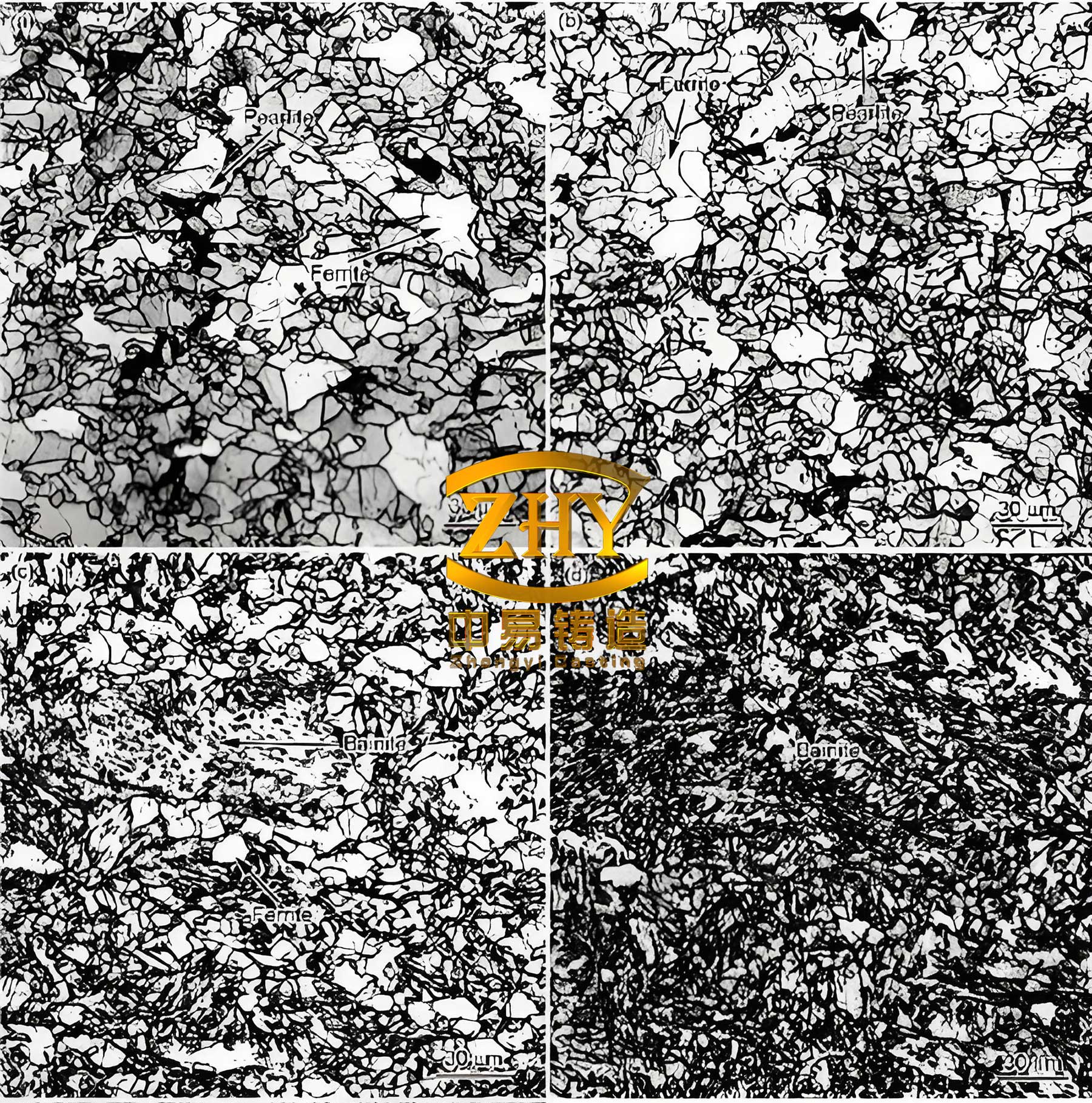
Mechanical testing of samples taken from the castings confirmed that the properties met and exceeded the QT450-15 specification. The typical values achieved were: Tensile Strength > 480 MPa, Yield Strength > 320 MPa, and Elongation > 18%. The enhanced feeding from the vacuum process resulted in a very dense microstructure with a uniform distribution of well-formed graphite spheroids and a predominantly ferritic matrix, explaining the high ductility. The absence of micro-shrinkage was verified through radiographic inspection. The ‘cast-to-size’ features were a resounding success. The ventilation holes and valve stem hole required no machining, and the bolt hole pre-forms reduced drilling time by over 60%. The economic analysis revealed a significant overall cost reduction per part, stemming from several factors: elimination of core-making materials and labor, drastic reduction in machining hours and tooling cost for the holes, and near-elimination of shot blasting and grinding labor due to the superior as-cast finish.
| Property / Characteristic | Specification (QT450-15) | Achieved Result (LFC Process) | Remarks |
|---|---|---|---|
| Tensile Strength (MPa) | ≥ 450 | 480 – 500 | Exceeds requirement |
| Yield Strength (MPa) | ≥ 310 | 320 – 340 | Exceeds requirement |
| Elongation (%) | ≥ 15 | 18 – 22 | Excellent ductility achieved |
| Wall Thickness Consistency | Drawing Tolerance (±1.0 mm) | ±0.5 mm | Superior precision from no-core process |
| Surface Finish (Ra, μm) | – | 12 – 25 | Excellent as-cast surface |
| Internal Soundness (X-ray) | No major shrinkage/porosity | Level 2 (ASTM E155) | High integrity due to vacuum feeding |
Concluding Synthesis
The development of this Lost Foam Casting process for the vacuum wheel rim demonstrates a paradigm shift in manufacturing complex, high-integrity spheroidal graphite cast iron components. The process successfully overcame the inherent limitations of traditional cored casting by providing an elegant, integrated solution. The key outcomes—perfect wall thickness control, exceptional surface quality, superior and consistent mechanical properties derived from a sound microstructure, and significant reductions in both machining and cleaning costs—collectively validate LFC as a highly competitive and technically superior process for this application. The successful ‘cast-to-size’ integration of features underscores the near-net-shape power of the method. Furthermore, the use of unbonded, reusable sand aligns with sustainable and environmentally conscious manufacturing principles. This project confirms that for intricate, safety-critical castings like the vacuum wheel rim, a well-engineered Lost Foam process is not just an alternative, but often the optimal choice for achieving a winning combination of performance, quality, and cost-effectiveness in spheroidal graphite cast iron production.