
Producing high-integrity, thick-walled, and geometrically complex castings from spheroidal graphite cast iron presents a significant and perennial challenge in the foundry industry. The inherent tendency of this material towards shrinkage porosity and shrinkage cavities has long been a focal point for metallurgists and process engineers. My experience, aligned with extensive industry research, confirms that the formation of these defects is not a simple matter of inadequate feeding but a complex interplay between the unique solidification characteristics of spheroidal graphite cast iron and the dynamic behavior of the mold cavity during pouring and cooling. This article synthesizes these principles and explores, from a first-person engineering perspective, how the sand-coated iron mold process, augmented by advanced simulation and specialized feeding systems, provides a robust solution for manufacturing high-quality, heavy-section spheroidal graphite iron castings.
The fundamental challenge stems from the distinctive solidification mechanism of spheroidal graphite cast iron. Unlike gray iron, the graphite precipitates as spheroids. During eutectic solidification, these graphite nodules become enveloped by an austenite shell early in their growth. This shell significantly hinders the diffusion of carbon atoms from the liquid melt to the growing graphite nodule, thereby slowing down the growth rate. Consequently, the completion of the eutectic reaction depends not only on the growth of existing eutectic cells but also on the continual nucleation of new ones. This results in a broad solidification temperature range, leading to a pasty or mushy freezing mode where solid and liquid phases coexist across a wide section of the casting for an extended period. This mushy zone can easily impede the flow of liquid metal for feeding late-solidifying regions.
The volumetric changes during the cooling and solidification of spheroidal graphite cast iron are complex and non-linear, encompassing both the alloy’s intrinsic specific volume changes and the dimensional changes of the mold cavity itself. Experimental studies have reported varying sequences: initial (pre-eutectic) expansion, followed by contraction, then significant eutectic expansion due to graphite precipitation, and final contraction. The net result can be either a slight expansion or contraction, heavily influenced by metallurgical and process factors. The key volumetric stages can be conceptually summarized by the following relation, where the net volume change $V_{net}$ determines the feeding requirement:
$$ V_{net} = V_{liquid\_shrinkage} + V_{solidification\_shrinkage} + V_{graphite\_expansion} $$
In this equation, $V_{liquid\_shrinkage}$ and $V_{solidification\_shrinkage}$ are negative (contractions), while $V_{graphite\_expansion}$ is positive. The outcome depends on their magnitude and timing. Crucially, the expansion from graphite formation can be harnessed for self-feeding if the mold is rigid enough to contain it. The factors influencing the magnitude of eutectic expansion and mold wall movement are multifaceted:
| Factor | Influence on Eutectic Expansion / Mold Behavior |
|---|---|
| Carbon Equivalent (CE) | Maximum expansion force near the eutectic composition. |
| Nodule Count & Morphology | Higher nodule count and more spherical graphite increase expansion. Uniform, medium-sized nodules promote maximum expansion. |
| Inoculation | Increased inoculation generally increases expansion force. |
| Mold Stiffness | Higher stiffness (e.g., iron mold) reduces cavity enlargement, containing expansion for self-feeding. |
| Mold Type | Green sand molds exhibit progressive cavity enlargement; dry sand and rigid metal molds show less enlargement or even contraction. |
| Pouring Temperature | Higher pouring temperatures can reduce the net expansion effect. |
Simultaneously, the mold cavity is not a static container. Upon receiving the molten metal, the mold wall heats up and can deform. In a green sand mold, the cavity often enlarges progressively during solidification due to sand expansion and binder breakdown, increasing the demand for liquid feed metal. In contrast, a rigid metal mold experiences initial thermal expansion but then stabilizes or even contracts, effectively resisting the internal pressure from the solidifying spheroidal graphite cast iron and enabling the utilization of graphite expansion for internal feeding. This concept of “high rigidity” is critical; it refers to a mold that maintains or reduces its cavity size after the in-gates have sealed, not merely one that is initially dimensionally stable.
When selecting a casting process for thick-walled spheroidal graphite cast iron components, several traditional methods are considered, each with notable limitations:
- Resin-Bonded Sand: Offers good strength and stability but is often cost-prohibitive for high-volume production due to high sand-to-metal ratios and resin costs. It can also lead to gas defects and environmental concerns, and is generally suited for low-volume, large castings.
- Green Sand Molding: While economical and efficient, its inherent low rigidity leads to significant mold wall movement. This necessitates large, inefficient feeder heads (risers) and often the addition of chilling materials to achieve directional solidification, resulting in low yield and potential inconsistency for high-grade spheroidal graphite cast iron.
The sand-coated iron mold process emerges as a superior alternative, particularly for medium-to-high volume production of complex, thick-section castings. This hybrid process involves creating a thin shell (typically 5-15 mm) of resin-coated sand on the surfaces of a reusable iron mold. The resulting mold assembly combines the benefits of shell molding (excellent surface finish, dimensional accuracy) with the profound advantages of a rigid metal mold. The iron mold provides extremely high stiffness, containing the graphite expansion to promote self-feeding, while the thin sand layer eliminates the chill effect that would cause white iron formation in a pure metal die. The process offers high cooling rates, leading to dense microstructure and superior mechanical properties often in the as-cast condition. Furthermore, it is highly amenable to automation, has a very low sand-to-metal ratio (often below 0.3), and provides a cleaner working environment.
The efficacy of this process is maximized when coupled with advanced simulation software. Numerical simulation allows for the visualization of filling, solidification, and cooling, enabling the prediction of shrinkage defects, optimization of feeder size and placement, and evaluation of thermal gradients before any metal is poured. It transforms process design from an empirical art into a science-based engineering activity. Key analysis capabilities include predicting solidification time and isolated liquid regions, optimizing riser design for maximum efficiency, and ensuring proper thermal control through the mold and chilling design.
A concrete case study involving a thick-walled, complex pulley wheel casting for a heavy-duty application illustrates this integrated approach. The component, weighing 134 kg and required to meet QT600-3 specifications (with actual tensile strength exceeding 750 MPa and specific hardness uniformity), demanded 100% soundness verified by ultrasonic testing.
Technical Specifications & Challenge: The casting featured significant variation in wall thickness, from 15 mm in the spokes to 85 mm at the hub and rim junctions. The primary challenge was to eliminate shrinkage porosity in these heavy sections while maintaining dimensional accuracy and mechanical properties.
Process Design & Simulation: Two distinct gating and feeding philosophies were developed and simulated under identical boundary conditions (iron mold, sand coating thickness, alloy properties).
- Scheme A (Riserless with Chills): Based on the “equalization solidification” theory, this design utilized tangential gating and strategically placed chills in the heavy sections to equalize cooling rates and promote self-feeding via graphite expansion. A small conventional riser was placed on the gating system primarily for slag trapping. The calculated casting yield was 83.5%.
- Scheme B (Directed Feeding with Exothermic Risers): This design followed a “directional solidification” approach. A top-pouring system with a filtered sprue/riser was used, supplemented by three exothermic side risers placed directly on the critical hot spots. The exothermic riser combines a heat-generating reaction with insulating materials, significantly extending its liquid life and improving feeding efficiency (typically 30-35%). The calculated casting yield was 93.8%.
The simulation results were decisive. Scheme A showed isolated liquid regions in the heavy sections, indicating a risk of micro-shrinkage that would rely entirely on perfectly contained graphite expansion. Scheme B clearly demonstrated open feeding channels from the hot spots to the risers throughout the solidification process, confirming the effectiveness of the directed feeding strategy.
Production & Metallurgical Control: Production was executed using the sand-coated iron mold process with Scheme B. The melting base was high-quality steel scrap, treated with specialized graphitizing inoculants. The spheroidal graphite cast iron was produced using a sandwich treatment with a low-rare earth magnesium ferrosilicon alloy (KM-071), followed by intensive inoculation (both in-mold and late stream) to ensure high nodule count and uniformity. Key process parameters and the resulting chemical composition are summarized below:
| Element | Target Range (wt.%) |
|---|---|
| C | 3.4 – 3.9 |
| Si | 2.0 – 2.4 |
| Mn | 0.1 – 0.6 |
| P | ≤ 0.05 |
| S | ≤ 0.02 |
| Cu | 0.2 – 0.6 |
| Mgres | 0.035 – 0.055 |
| RE | 0.02 – 0.04 |
The sand coating thickness was tailored based on simulation: 12-15 mm in the gating areas, 6-8 mm at critical junctions, and 8-10 mm elsewhere, achieving an overall sand-to-metal ratio of approximately 0.2. Adefficient mold venting was incorporated to prevent gas-related defects.
Results & Validation: The castings produced via Scheme A, when sectioned, revealed unresolved shrinkage porosity in the thick sections, validating the simulation prediction. The premature graphite expansion during the open-feeding stage likely expelled liquid from the cavity, hindering effective feeding. For Scheme B, the results were exemplary:
- Mechanical Properties (from casting body): Tensile strength: 858 MPa, Elongation: 5.2%, Hardness: 242-255 HB (meeting the strict uniformity requirement).
- Non-Destructive & Destructive Testing: 100% passed ultrasonic inspection. Dye-penetrant testing on sectioned castings from the riser-fed areas showed completely sound, dense material with no shrinkage defects.
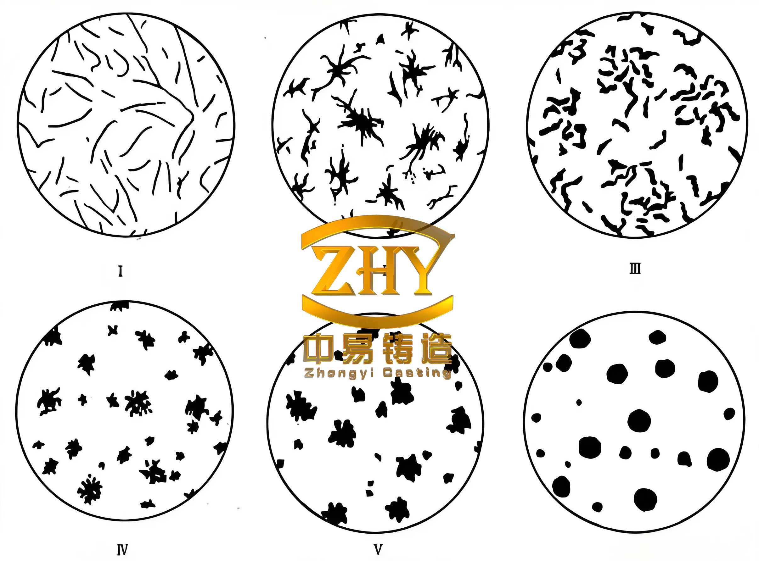
- Microstructure: Metallographic analysis of the heaviest section showed graphite nodularity >90% (Grade 2), nodule size 6-7, and a pearlitic matrix >85%, fulfilling all customer specifications.
This case study underscores several critical conclusions for producing thick-walled complex spheroidal graphite cast iron. First, while the sand-coated iron mold process is excellent for uniform wall sections, complex geometries with drastic thickness variations require active, directed feeding systems like exothermic risers to supplement the self-feeding mechanism. The process rigidity alone is not always sufficient. Second, a dogmatic adherence to a single solidification theory (equalization or directional) is often counterproductive. A pragmatic, hybrid approach informed by simulation is essential. The feeder design must ensure open channels to the thermal centers, described by the condition that the solidification time of the feeder neck $t_{neck}$ must be greater than that of the casting hot spot $t_{hotspot}$:
$$ t_{neck} > t_{hotspot} $$
This is achieved by designing a riser neck with a sufficient modulus. Finally, the integration of robust metallurgical control for consistent high-quality iron, advanced simulation for predictive optimization, the high-rigidity sand-coated iron mold process, and high-efficiency feeding technology forms a powerful, synergistic methodology. This approach not only guarantees the production of sound, high-performance spheroidal graphite cast iron castings but also significantly improves yield, reduces weight and scrap, and lowers total production cost, delivering substantial technical and economic benefits.