
The cylinder liner stands as a core component within an internal combustion engine. With the ongoing evolution of engine technology towards higher speeds, greater power densities, increased peak firing pressures, lower emissions, and enhanced overall performance, the demands placed on the performance characteristics of cylinder liners have become increasingly stringent. During engine operation, the inner bore of the cylinder liner serves as the primary friction surface for the reciprocating piston assembly. Consequently, it must possess high strength, excellent resistance to elevated temperatures, and superior wear characteristics. The reliability and service life of the cylinder liner are, therefore, critically important to the durability of the entire engine. Spheroidal graphite cast iron, owing to its excellent combination of mechanical properties and superior resistance to cavitation erosion, has found widespread application among engine manufacturers. This material’s microstructure, characterized by graphite nodules embedded in a metallic matrix, is key to its performance.
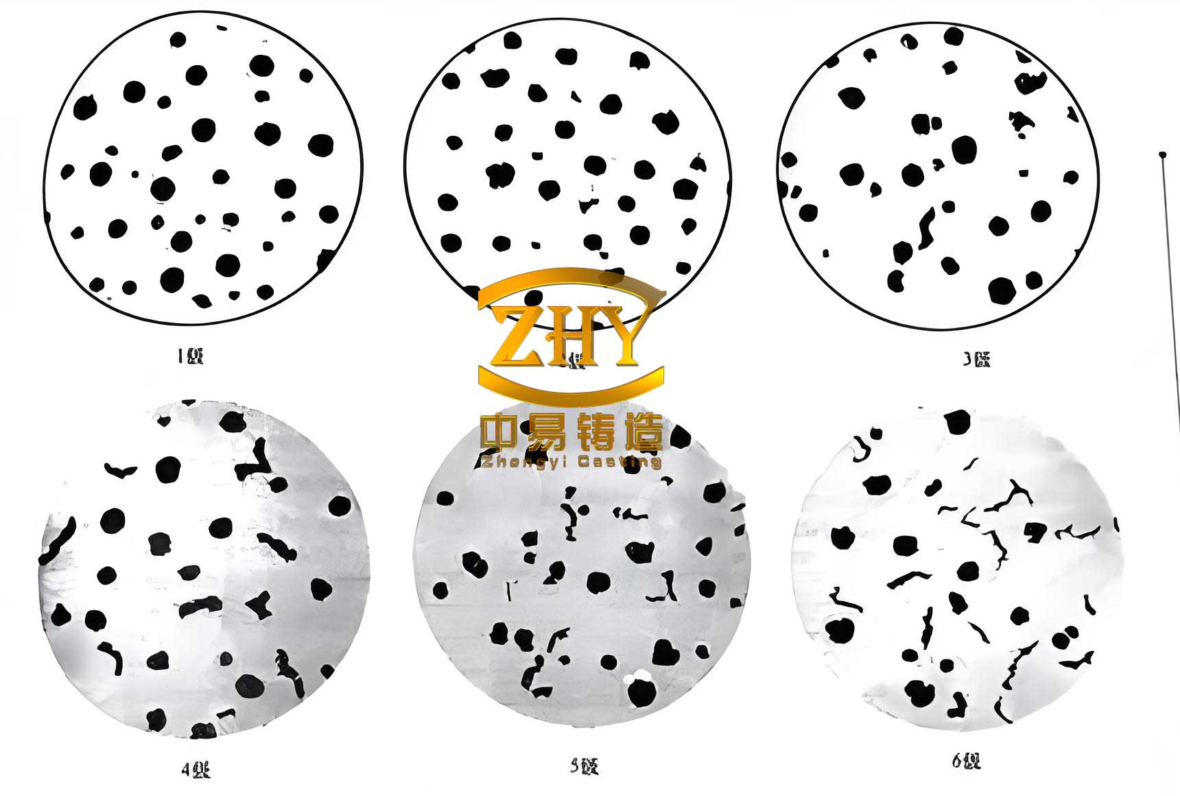
However, in the production of spheroidal graphite cast iron cylinder liners via a horizontal centrifugal casting process utilizing water-cooled permanent molds, a specific internal defect was observed in sections with greater wall thickness. This defect manifests as an area of chilled, carbidic (white iron) structure within the otherwise ductile iron matrix and is commonly referred to as “inverse chill” or “reverse chill.” Inverse chill is a latent defect hidden within the interior of a spheroidal graphite cast iron casting. It detrimentally affects the mechanical properties of the component, increases the difficulty of subsequent machining operations, reduces tool life, and directly impacts both casting quality and economic efficiency. The formation of inverse chill is primarily associated with factors such as micro-segregation of alloying elements, the effectiveness of melt inoculation, and the local solidification conditions within the casting.
The advancement of computer-based numerical simulation technology has provided foundry engineers with a powerful new tool for exploring the filling and solidification behavior inherent to centrifugal casting processes. While current casting simulation software may not yet offer a perfectly mature model for horizontal centrifugal casting, and some discrepancies with actual production conditions may exist, its advantages—such as shortened development cycles, reduced research costs, and ease of adjusting process parameters—make it an increasingly vital asset in guiding practical production and facilitating process improvements. This article details the numerical simulation of the solidification process for a specific cylinder liner casting. By investigating the solidification sequence, temperature field evolution, and solid-liquid phase distribution post-filling, the location prone to inverse chill defects was accurately identified. This simulation-based insight provided crucial data to support targeted optimization of the casting process.
Mathematical Modeling of the Process
The filling phase in horizontal centrifugal casting involves a complex, transient flow of a viscous, incompressible fluid with a free surface. The fluid motion during mold filling must satisfy the fundamental laws of conservation of mass and momentum. The governing equations for the filling process are the continuity equation and the Navier-Stokes equations.
1. Continuity Equation (Conservation of Mass):
The continuity equation for an incompressible flow is expressed as:
$$\nabla \cdot \vec{V} = 0$$
or, in its expanded form for a Cartesian coordinate system:
$$ \frac{\partial u}{\partial x} + \frac{\partial v}{\partial y} + \frac{\partial w}{\partial z} = 0 $$
where \( \vec{V} \) is the velocity vector, and \( u \), \( v \), and \( w \) are its velocity components in the \( x \), \( y \), and \( z \) directions, respectively.
2. Navier-Stokes Equations (Conservation of Momentum):
The momentum conservation equation for a Newtonian fluid is given by:
$$ \frac{\partial (\rho \phi)}{\partial t} + \nabla \cdot (\rho \vec{V} \phi) = \nabla \cdot (\mu \nabla \phi) + S_u – \nabla P $$
In this equation:
- \( \rho \) represents the fluid density (kg/m³).
- \( t \) is time (s).
- \( \phi \) stands for a velocity component.
- \( \mu \) is the dynamic viscosity (Pa·s).
- \( S_u \) denotes a source term for momentum.
- \( P \) is the pressure (Pa).
3. Energy Equation (Heat Transfer and Solidification):
Simulating the temperature field during mold filling and solidification requires coupling the fluid flow with heat transfer. The thermal behavior, encompassing convective flow of the liquid and conductive heat transfer during solidification, is governed by the energy conservation equation, often expressed as a heat balance equation:
$$ \rho c_p \frac{D T}{D t} = \nabla \cdot (k \nabla T) + \dot{Q} $$
where:
- \( c_p \) is the specific heat capacity (J/(kg·K)).
- \( T \) is the temperature (K).
- \( k \) is the thermal conductivity (W/(m·K)).
- \( \dot{Q} \) represents internal heat sources, which includes the latent heat of fusion released during phase change. This term is typically handled using enthalpy methods in solidification simulations.
- \( \frac{D T}{D t} \) is the material derivative of temperature, accounting for both local and convective changes.
This equation is solved concurrently with the flow equations to predict the evolution of the temperature field throughout the process.
Simulation of the Initial Casting Process
Physical Model and Setup
The subject of this study is a cylinder liner casting with a maximum outer diameter of 140 mm, a length of 298 mm, and a maximum wall thickness of 19 mm. The rough casting geometry, including machining allowances, is defined with an internal diameter machining allowance of 7-9 mm per side, a feed-end allowance of 40 mm, and a tail-end allowance of 20 mm. The assembly comprises the mold, end plates (chill plates), the casting itself, and the insulating coating applied to the mold surface.
For the simulation, the computational domain was discretized using an unstructured mesh predominantly consisting of tetrahedral elements. To balance accuracy and computational efficiency, the mesh density was increased for critical regions such as the insulating coating and the casting, while a coarser mesh was applied to the mold and end plates. The pouring gate was defined at the inner surface of the casting. The final mesh contained approximately 100,000 surface elements and 720,000 volume elements.
Process Parameters and Material Properties
The casting material is a pearlitic grade of spheroidal graphite cast iron. Its typical chemical composition is summarized in Table 1.
| Element | C | Si | Mn | Cu | Ni | Mg | S | Ce |
|---|---|---|---|---|---|---|---|---|
| Content | 3.4-3.9 | 2.4-2.9 | ≤0.5 | 1.0-1.3 | 0.1-0.3 | ≥0.035 | <0.02 | <0.04 |
The mold and end plates are made of gray iron (HT250). The production process employs a multi-station, water-cooled horizontal centrifugal casting machine with a wire-feeding nodularization treatment. Key initial process parameters and thermophysical boundary conditions are listed in Table 2.
| Parameter | Value or Range |
|---|---|
| Pouring Temperature | 1340 – 1390 °C |
| Pouring Rate | 2.0 – 2.5 kg/s |
| Mold Pre-heat Temperature | 200 – 300 °C |
| Heat Transfer Coefficient: Casting/Coating/Mold | 500 W·m⁻²·K⁻¹ |
| Heat Transfer Coefficient: Mold/Cooling Water | 5000 W·m⁻²·K⁻¹ |
| Heat Transfer Coefficient: Casting Inner Surface/Air | 20 – 60 W·m⁻²·K⁻¹ |
The rotational speed for centrifugal casting is a critical parameter. In practice, it is commonly determined using Konstantinov’s empirical formula:
$$ n = \frac{29.9}{\sqrt{r}} \sqrt{G} $$
where:
- \( n \) is the rotational speed of the mold (rpm).
- \( G \) is the gravitational coefficient (G-factor), typically ranging from 40 to 110 for such castings.
- \( r \) is the inner radius of the casting (m).
For the given cylinder liner, the calculated speed range was 840 to 1380 rpm. Based on production experience, an initial rotational speed of 1200 rpm was selected for the simulation.
Analysis of Initial Simulation Results
The simulated temperature field during solidification under the initial process conditions revealed distinct thermal patterns. The outer surface of the casting, in contact with the insulating coating and the water-cooled mold, experiences the most rapid heat extraction, causing it to solidify first. The inner surface of the rotating casting loses heat primarily via radiation and convection to the ambient air, leading to its temperature being lower than the mid-wall region but higher than the outer surface. The ends of the casting, in contact with the chill plates, also cool rapidly. Due to the variation in wall thickness, the thicker section at one end acts as a thermal mass or “hot spot,” retaining heat longer than surrounding areas.
This non-uniform cooling creates a specific temperature profile. At a simulation time of t = 150 seconds, the temperature distribution showed the outer layer at approximately 1120°C, the inner layer at 1160°C, and the mid-wall region in the thick section reaching about 1180°C. This “sandwich” profile, with the hottest zone in the middle of the wall, is a direct consequence of the bidirectional heat extraction (outer mold cooling and inner air cooling) coupled with the thermal mass effect.
The corresponding solid-liquid phase distribution at t = 150 s is the most critical output for defect prediction. The simulation clearly showed that solidification commenced simultaneously from the outer surface (towards the mold) and the inner surface (towards the air), as well as from both ends. The last region to fully solidify was a localized volume within the thick section of the casting wall, positioned closer to the inner surface. Measuring from this simulation, the center of this last-to-solidify “hot spot” was located approximately \( H = 7.8 \) mm from the inner surface of the rough casting blank.
In actual production using the initial process, metallographic examination of the castings confirmed the presence of inverse chill defects. The defective area, characterized by carbide formations, was consistently found at a distance of about 7 mm from the inner bore. The remarkable correlation between the simulated location of the final solidification spot and the actual defect location validated the accuracy of the simulation model. This proof confirmed that the numerical model could reliably predict the propensity and location of casting defects in this spheroidal graphite cast iron component, thereby providing a solid foundation for targeted process optimization.
Casting Process Optimization Strategy
The formation mechanism of inverse chill in spheroidal graphite cast iron is multifaceted, with theories including micro-segregation of carbide-promoting elements (like manganese) to the last-solidifying regions, fading of the inoculant effect during prolonged solidification, and a critical combination of local chemistry and cooling rate that promotes carbide stability over graphite formation. For this specific cylinder liner, the simulation results pointed decisively to the thermal condition as the primary controllable factor: the last-solidifying region was not at the geometrically thickest point relative to the mold, but was instead trapped internally due to the specific heat extraction pattern.
The core objective of the optimization, therefore, was to alter the solidification sequence to promote more directional cooling, ideally from the outer surface inward. The goal was to shift the last-solidifying region closer to the inner surface and, ideally, reduce its size and thermal severity to prevent the conditions that lead to inverse chill in the spheroidal graphite cast iron. The strategy involved modifying the local cooling intensity at the problematic thick section:
- Increase Cooling Water Flow: The cooling water flow rate across the segment of the mold corresponding to the casting’s thick section was selectively increased to enhance heat extraction from the outside.
- Reduce Insulating Coating Thickness: The thickness of the refractory insulating coating applied to the mold in the thick section was reduced. A thinner coating offers lower thermal resistance, allowing heat from the casting to be transferred more efficiently to the water-cooled mold.
- Modify End Cooling: Cooling conditions at the feed end were also adjusted to ensure a more uniform thermal gradient along the length of the casting.
These modifications were virtually tested by updating the simulation model with the new boundary conditions (higher heat transfer coefficients at the targeted outer surface areas). The results were significant. The optimized temperature field simulation showed a much more uniform gradient, with the outer surface remaining the coldest region throughout solidification. The “sandwich” effect was markedly reduced.
Most importantly, the solid-liquid distribution simulation for the optimized process, at t = 120 s, showed a complete change in the solidification pattern. The last region to solidify was now a much smaller volume located only about \( H = 3.5 \) mm from the inner surface. This represented a substantial shift of over 4 mm inward compared to the initial process. By moving the final solidification zone closer to the inner bore—which is entirely removed during machining—any potential microstructural inhomogeneity in that zone would be eliminated from the final part. Furthermore, the more directional solidification reduces the time available for element segregation and inoculant fade, mitigating other root causes of inverse chill in spheroidal graphite cast iron.
Validation and Conclusion
The optimized process parameters derived from the simulation study were implemented in actual production. A rigorous quality inspection regimen was followed, involving systematic metallographic examination of castings from the optimized process. The results confirmed the simulation’s predictions. The incidence of inverse chill defects was reduced to statistically negligible levels, with internal soundness yields exceeding 99.6%. All finished machined liners met the required specifications, validating the optimization as successful.
In summary, this work demonstrates the effective application of numerical simulation technology to address a complex foundry challenge in manufacturing spheroidal graphite cast iron components. The key conclusions are:
- Accurate Defect Prediction: Casting simulation software was successfully used to model the solidification process of a horizontal centrifugal cast spheroidal graphite cast iron cylinder liner. The simulation accurately predicted the location of the last-solidifying region, which correlated precisely with the observed location of inverse chill defects in production, thereby verifying the model’s validity.
- Effective Process Optimization: Based on the simulation insights, the casting process was optimized by selectively increasing the local cooling rate at the external mold surface adjacent to the casting’s thick section. This was achieved by increasing cooling water flow and reducing the insulating coating thickness in that specific area. The simulated result of the optimized process showed a drastic improvement in the solidification sequence, with the final hot spot shifting significantly inward towards the machined surface.
- Practical Validation and Benefit: The implementation of the optimized process in production successfully eliminated the inverse chill defect, resulting in high-quality spheroidal graphite cast iron castings with excellent machinability and consistent mechanical properties. This led to reduced scrap rates and lower machining costs.
- Foundation for Further Development: Beyond solving the immediate defect issue, this simulation-based understanding of the solidification characteristics provides a scientific foundation for future advancements. It opens the possibility for further optimizations, such as reducing the overall machining allowances now that the internal soundness zone is better controlled, thereby improving material yield and production efficiency for spheroidal graphite cast iron castings.
The methodology outlined here—combining numerical simulation with practical metallurgical knowledge—provides a powerful and generalizable framework for the design and troubleshooting of casting processes. It significantly shortens the development and problem-solving cycle, reduces costs associated with physical trial-and-error, and enhances the overall quality and reliability of engineered cast components made from materials like spheroidal graphite cast iron.