
In my extensive experience within the foundry industry, the production of high-integrity thick-walled components from Austempered Ductile Iron (ADI), a premium grade of spheroidal graphite cast iron, presents a unique set of challenges and opportunities. The exceptional combination of high strength, wear resistance, good ductility, and damping capacity makes ADI an ideal material for demanding applications. However, achieving consistent microstructural integrity—specifically, a high nodule count, uniform nodularity, and freedom from deleterious phases—in heavy sections is paramount for subsequent successful austempering heat treatment. This article details the systematic approach and critical control points we have developed and implemented for the stable mass production of thick-walled ADI blanks, drawing directly from hands-on practice. The foundational goal is always to produce a sound, high-quality spheroidal graphite cast iron casting as the precursor for heat treatment.
The core challenge with thick sections lies in managing the solidification dynamics. Longer solidification times increase the risk of graphite flotation, chunk graphite formation, carbide precipitation, and segregation. Therefore, every step of the process, from charge makeup to final pouring, must be meticulously designed to promote a fine, uniform matrix of graphite spheroids within a ferritic-pearlitic matrix in the as-cast state. The following sections elaborate on the key pillars of our production methodology.
1. Strategic Selection and Control of Raw Materials
The principle of “garbage in, garbage out” is profoundly true in metallurgy. The genetic inheritance from raw materials significantly impacts the final casting quality. For producing premium spheroidal graphite cast iron, we enforce strict specifications on all charge materials to minimize the introduction of harmful trace elements and ensure chemical consistency.
1.1 Pig Iron: We source high-purity, low-residual pig iron. The focus is on minimizing elements that promote carbide stability or interfere with graphite nodulization. Our typical specifications are: $ω(P) ≤ 0.04\%$ and $ω(S) ≤ 0.02\%$. Lower levels are always preferred to reduce the potential for phosphide eutectic and slag formation during treatment.
1.2 Steel Scrap: To avoid the unpredictable influence of alloying residues, we exclusively use selected low-carbon, low-residual carbon steel scrap. It must be clean, dry, and free from rust, oil, and coatings. We qualify suppliers based on their ability to provide material with consistent chemistry: $ω(P) ≤ 0.035\%$ and $ω(S) ≤ 0.025\%$.
1.3 Returns (Gates and Risers): To prevent the accumulation of trace elements from other production lines, we segregate and recycle returns from ADI production separately. This closed-loop system for internal returns is crucial for long-term chemical stability.
1.4 Carburizers: The choice of carburizer is critical not just for carbon recovery but also for nucleation. We use high-purity, calcined graphite-based carburizers. The dissolution of graphite particles provides effective nucleation sites. Key specifications are detailed in Table 1.
| Parameter | Requirement (wt.%) | Purpose/Rationale |
|---|---|---|
| Fixed Carbon | ≥ 98.5 | High carbon yield, low ash. |
| Ash Content | ≤ 0.5 | Minimizes slag formation. |
| Volatiles | ≤ 0.5 | Ensures stable, clean addition. |
| Sulfur | ≤ 0.05 | Prevents excessive sulfur load. |
| Nitrogen | ≤ 0.03 | Avoids nitride formation and pinhole defects. |
| Moisture | ≤ 0.5 | Prevents hydrogen pick-up and explosion risk. |
| Particle Size (Furnace) | 1 – 5 mm | Optimal for dissolution in molten bath. |
1.5 Pre-conditioning Agents: We often employ high-purity silicon carbide (SiC) as a pre-conditioning agent. SiC dissolves into the melt, providing both silicon and carbon. More importantly, the undissolved SiC particles act as potent heterogeneous nucleation sites for graphite during solidification. The reaction can be conceptually represented as:
$$ \text{SiC (s)} \rightarrow [\text{Si}] + [\text{C}] $$
We use a metallurgical grade SiC (≈90% SiC) for furnace additions and a higher purity grade (>98.5% SiC) for ladle treatment. The particle size selection follows similar logic to the carburizer.
2. Precise Chemical Composition Design
The chemical composition is the blueprint for the microstructure. For thick-walled spheroidal graphite cast iron destined for austempering, the balance between graphitization potential, hardenability, and mechanical properties is delicate.
2.1 Carbon Equivalent (CE): The Carbon Equivalent is a fundamental parameter predicting the eutectic point and influencing fluidity and shrinkage behavior. For our thick-section castings, we aim for a hypereutectic composition to ensure good feeding but strictly control it to prevent graphite flotation. The classic formula is:
$$ CE = C + \frac{1}{3}(Si + P) $$
However, in practice, we use a modified version that accounts for our specific base. Our target range is $4.3\% ≤ CE ≤ 4.6\%$. Operating near the eutectic point (typically ~4.3% for our system) promotes a finer graphite structure. The exact target is determined through prior experimentation for each casting geometry.
2.2 Major Element Control: The interplay between carbon and silicon is managed within the CE framework. We deliberately keep silicon at a moderate level to avoid its ferrite-strengthening effect from becoming excessive in the as-cast structure and to minimize the risk of forming chunk graphite in heavy sections. Table 2 summarizes our standard ranges for key elements.
| Element | Target Range | Rationale & Control Method |
|---|---|---|
| Carbon (C) | 3.5 – 3.8 | Balanced with Si to achieve target CE. Controlled via carburizer addition and charge calculation. Analyzed by IR combustion. |
| Silicon (Si) | 2.2 – 2.6 | Promotes graphitization but limited to prevent chunk graphite. Added via FeSi alloy. Analyzed by OES. |
| Manganese (Mn) | 0.2 – 0.4 | Minimized due to strong segregation tendency to cell boundaries, which can embrittle the matrix. Controlled via steel scrap selection. |
| Phosphorus (P) | ≤ 0.04 | Strictly minimized to avoid brittle phosphide networks at grain boundaries. |
| Sulfur (S) | ≤ 0.015 (post-treatment) | Extremely low post-inoculation levels are vital. High S consumes Mg, creates slag, and impairs nodularity. |
Accurate chemical analysis is non-negotiable. We utilize an infrared carbon/sulfur analyzer for C and S, and optical emission spectroscopy (OES) for other elements. Regular calibration against wet chemical methods ensures data reliability.
2.3 Alloying Elements for Hardenability: To ensure through-hardening during the austempering process of thick sections, alloying elements like Copper and Molybdenum are added. Their primary role is to increase the hardenability by delaying the transformation of austenite. The required amount is a function of section size and austempering temperature. We have established, in collaboration with our heat-treatment partners, that for sections up to ~90 mm, an addition within these ranges is sufficient:
$$ ω(Cu) = 0.6 – 0.9\% $$
$$ ω(Mo) = 0.1 – 0.3\% $$
Nickel is sometimes used as an alternative. The combined effect on hardenability can be estimated using multiplying factors, though final optimization is empirical.
2.4 Trace and Tramp Elements: This is where raw material control pays off. Elements like Pb, Bi, Sb, Ti, As, etc., even in ppm levels, can degrade nodularity or promote undesirable graphite shapes. We enforce a stringent limit: the combined total of all detrimental trace elements should be less than 0.1%, and the sum of anti-nodularizing elements (like Ti, Sb, Pb, Bi) must satisfy the condition:
$$ \sum (ω(Ti), ω(Sb), ω(Pb), ω(Bi)…) < 0.01\% $$
This rigorous control is essential for producing consistent, high-quality spheroidal graphite cast iron.
3. Thermal Management: From Melting to Pouring
Temperature is a critical process variable that influences dissolution, homogenization, slag formation, and ultimately, solidification structure.
3.1 Superheating and Holding: After the charge is fully melted, we intentionally superheat the bath to 1510°C – 1530°C and hold for 10-15 minutes. This practice, which we consider vital, serves multiple purposes:
- Ensures complete dissolution of carburizer and alloying elements.
- Promotes homogenization of temperature and chemistry.
- Allows for the agglomeration and flotation of non-metallic inclusions, which are then removed as slag.
- Helps break down any “genetic” inheritance from the charge materials, leading to a more responsive melt during inoculation.
The thermal energy input can be related to the holding time $t$ and temperature $T$ above the liquidus $T_L$. While not a formal equation, the concept is to achieve a sufficient thermal budget:
$$ \text{Thermal Effect} \propto \int_{0}^{t} (T – T_L) \, dt $$
3.2 Pouring Temperature Strategy: The choice of pouring temperature $T_p$ is a compromise. Too high, and it encourages shrinkage porosity, metal-mold reaction, and graphite flotation in thick sections. Too low, and it risks cold shuts, mistruns, and poor dissolution of late ladle additions. For our complex, thick-walled castings, we set $T_p$ based on the thinnest section to ensure fill, typically in the range of 1350°C – 1380°C. The temperature drop $ΔT$ during transfer and pouring is carefully monitored and accounted for in our scheduling. It can be estimated as:
$$ ΔT = k \cdot t_{transfer} + ε \cdot A_{ladle} \cdot (T_{ladle} – T_{ambient}) $$
where $k$ and $ε$ are constants related to ladle lining and ambient conditions, $t_{transfer}$ is time, and $A$ is surface area.
3.3 Pouring Practice: We use pre-heated, refractory-lined ladles with insulating lids to minimize temperature loss and oxidation. A strict protocol is followed: the total time from the end of the spheroidization treatment to the completion of pouring for that ladle must not exceed 10 minutes. This prevents both excessive temperature drop and the deleterious effects of fading nodularity and inoculation.
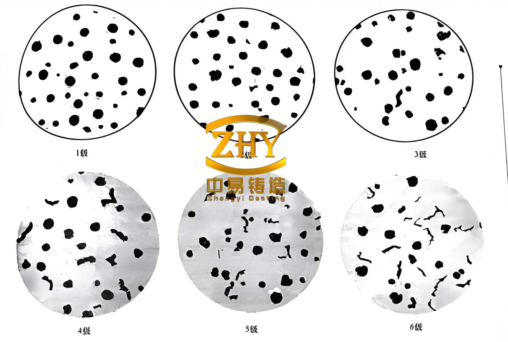
4. Advanced Spheroidization and Inoculation Techniques
This is the heart of producing spheroidal graphite cast iron. The goal is to transform the flake graphite structure inherent to cast iron into a spheroidal one and to ensure a high nodule count that remains fine even in slow-cooling sections.
4.1 Spheroidizing Agent Selection: For thick sections, we avoid high-rare-earth alloys that can lead to “ghost cell” boundaries or promote chunk graphite. We prefer a magnesium-ferrosilicon alloy with low rare earth content (around 1% light rare earths or a mix) and a magnesium content of 5-6%. The reaction is exothermic:
$$ [Mg] + [S] → MgS (slag) $$
$$ 3[Mg] + 4[O] → 2MgO + MgO·SiO_2 (slag) $$
The residual magnesium $[Mg]_{res}$ after these desulfurization and deoxidation reactions is the key. We aim for $[Mg]_{res} ≈ 0.03 – 0.05\%$, which is sufficient for nodulization without exacerbating shrinkage tendencies.
4.2 Inoculation Philosophy and Practice: Inoculation is not a single event but a process. We use powerful, long-lasting inoculants based on barium, zirconium, or rare earths to combat fading. Our strategy involves multiple stages:
- Primary Inoculation: A Ba-Ca-FeSi alloy is added to the ladle during or immediately after the Mg-treatment.
- Stream Inoculation: During pouring, a fine-grained FeSi alloy containing Zr or Sr is added into the metal stream via a calibrated feeder. This provides fresh, active nuclei just before solidification.
The effectiveness of inoculation in increasing nodule count $N$ can be conceptually modeled as:
$$ N = N_0 + k_I \cdot C_I \cdot e^{-λt} $$
where $N_0$ is the base nucleation from preconditioning, $k_I$ is a potency factor, $C_I$ is the inoculant concentration, $λ$ is the fading constant, and $t$ is the time delay. Our multi-stage approach minimizes the negative impact of $t$.
Table 3 summarizes a typical treatment sequence and parameters for a 1.5-ton heat.
| Step | Material | Amount (kg) | Method | Target/Outcome |
|---|---|---|---|---|
| Spheroidization | 5% Mg, 1% RE FeSi | 15-18 (1.0-1.2%) | Sandwich method in preheated ladle | Residual Mg: 0.04-0.05% |
| Primary Inoculation | Ba-Ca-FeSi (75% Si) | 7.5 (0.5%) | Added to metal stream during transfer | Bulks nodule count, counters fading. |
| Cover Slag | Deslagging Compound | As needed | Added after treatment | Remove MgO/SiO2 slag. |
| Stream Inoculation | Zr-FeSi (85% Si) | ~0.3% of poured weight | Automatic feeder at pouring lip | Provides fresh nuclei for each casting. |
5. Integrated Process Control and Results
The synthesis of all these controlled steps yields a predictable and high-quality as-cast spheroidal graphite cast iron blank. The microstructural targets for our blanks before austempering are: nodularity ≥ 90% (often exceeding 95%), nodule count ≥ 120 nodules/mm² in critical sections, and carbides + inclusions + microshrinkage < 1.5% by area fraction. The nodule count $N_v$ (per mm³) is related to the cooling rate $\dot{T}$, but through effective inoculation, we maintain a high count even in thick sections where $\dot{T}$ is low. An empirical relationship we observe is:
$$ N_v \approx A \cdot \exp(-B \cdot d) + C \cdot I_{eff} $$
where $d$ is the section thickness, $A$, $B$, $C$ are constants, and $I_{eff}$ is an effectiveness factor for our inoculation practice.
The mechanical properties of the blank itself are also monitored. Typical as-cast properties for our ferritic-pearlitic spheroidal graphite cast iron blanks are: Tensile Strength: 450-550 MPa, Yield Strength: 280-350 MPa, Elongation: 12-18%. These provide a robust foundation for the subsequent austempering cycle.
Implementing this comprehensive control regimen has eliminated issues such as intercellular carbides in heavy sections and random occurrences of exploded or chunky graphite. The consistency of the as-cast structure directly translates into consistent and superior ADI properties after heat treatment, including high tensile strength (>850 MPa) and good impact toughness.
6. Conclusion and Forward Outlook
Producing thick-walled Austempered Ductile Iron blanks of consistent high quality is not a matter of chance but of rigorous, science-informed engineering practice. From my perspective, the journey involves a deep commitment to raw material purity, precise chemical design favoring graphitization, intelligent thermal management to refine the melt, and a robust, multi-stage spheroidization and inoculation regime. Every element, from the choice of carburizer to the seconds counted during pouring, contributes to the final goal: a flawless, homogeneous spheroidal graphite cast iron microstructure.
The process outlined here—centered on control and consistency—has proven itself in stable mass production. It underscores that the performance potential of ADI is unlocked first in the foundry, with the production of a superior blank. This holistic approach to manufacturing spheroidal graphite cast iron for demanding applications remains the cornerstone of our technical philosophy and production success.