
The V-shape thrust rod is a critical component within the balance suspension system of commercial vehicles, responsible for transmitting longitudinal and lateral loads, as well as corresponding moments, between the axle and the frame to ensure driving stability. Traditionally, these components are fabricated from carbon steel, utilizing a combination of forged ends (ball seats) and a connecting steel tube. The assembly processes—such as hot riveting or friction welding—are inherently multi-step, lengthy, and costly. Furthermore, these joining methods introduce residual stresses and potential stress concentration zones at the interfaces, which can be detrimental to long-term fatigue performance.
This article presents an innovative engineering solution: the replacement of the traditional fabricated steel assembly with a single-piece, integrally cast component made from high-strength spheroidal graphite cast iron. The adoption of spheroidal graphite cast iron offers a compelling set of advantages. Firstly, it enables “cast-for-integration,” eliminating assembly-related stresses and simplifying the production workflow to a single molding and casting operation, thereby reducing cost and cycle time. Secondly, spheroidal graphite cast iron provides an excellent combination of strength, ductility, and castability. The spheroidal graphite nodules act as natural crack arresters, enhancing toughness and fatigue resistance. Thirdly, the lower density of spheroidal graphite cast iron (approximately 7.1-7.3 g/cm³) compared to forged steel (7.85 g/cm³) contributes directly to vehicle lightweighting objectives. The primary challenge lies in designing a castable geometry that meets or exceeds the structural performance benchmarks set by its steel counterpart.
Structural Design and Material Selection
The core design philosophy shifts from an assembly to a monolithic structure. The conventional tubular section is re-envisioned as an H-shaped beam that seamlessly integrates with the ball socket ends. This H-section offers superior bending stiffness per unit mass compared to a circular tube and is more conducive to the flow and solidification characteristics of molten spheroidal graphite cast iron. As no direct standard exists for H-sections in spheroidal graphite cast iron design, principles for steel sections under axial compression from relevant standards were adapted, with a focus on optimizing the flange width-to-thickness and web height-to-thickness ratios to prevent local buckling while minimizing weight.
The key cross-sectional parameters of the designed H-beam for the spheroidal graphite cast iron thrust rod are summarized in the table below. The asymmetric flange heights (H1 and H2) are a result of topology optimization, reducing material where stress levels are lower, thus contributing to overall weight reduction.
| Parameter | Symbol | Value (mm) |
|---|---|---|
| Left Flange Height | H1 | 43.8 |
| Right Flange Height | H2 | 28.3 |
| Flange Thickness | m | 7.7 |
| Web Thickness | n | 7.0 |
| Total Section Width | B | 51.1 |
Despite the H-beam’s slightly larger cross-sectional area than a tube, the elimination of the solid forged steel ball sockets and overlapping joint regions results in a net mass reduction. A comparative calculation shows the monolithic spheroidal graphite cast iron design achieves a 9% weight saving over the traditional fabricated steel thrust rod.
The material of choice is as-cast grade QT700-6 spheroidal graphite cast iron. This grade provides a minimum tensile strength of 700 MPa, a yield strength exceeding 420 MPa, and an elongation of 6%, offering the necessary high strength and toughness for this demanding application. The “as-cast” condition is strategically selected to avoid the energy consumption, cost, and potential distortion associated with post-casting heat treatments like normalizing. The mechanical properties of QT700-6 are given by:
$$ R_m \geq 700 \text{ MPa}, \quad R_{p0.2} \geq 420 \text{ MPa}, \quad A \geq 6\% $$
where $R_m$ is the tensile strength, $R_{p0.2}$ is the 0.2% offset yield strength, and $A$ is the percentage elongation.
The second moment of area (I) for the H-section, crucial for bending stiffness, can be calculated by summing the contributions of the web and the two flanges. For bending about the horizontal axis (z-axis), the formula is:
$$ I_{yy} = \frac{n \cdot H_w^3}{12} + 2 \left[ \frac{m \cdot B_f^3}{12} + m \cdot B_f \cdot \left( \frac{H_w + m}{2} \right)^2 \right] $$
where $H_w$ is the web height (approximated as the average of H1 and H2), $B_f$ is the flange width, $n$ is the web thickness, and $m$ is the flange thickness. This high moment of inertia contributes to the rod’s structural rigidity.
Finite Element Analysis for Structural Verification
To verify the structural integrity of the new design, a comprehensive finite element analysis (FEA) was conducted. A full assembly model was created, including the spheroidal graphite cast iron rod, the spherical joint’s steel core pin, end caps, retaining ring, and the rubber bushing. The rubber was modeled using a 3rd-order Ogden hyperelastic constitutive model to accurately capture its non-linear behavior.
The material properties defined in the FEA software are listed below:
| Material | Density (g/cm³) | Young’s Modulus (GPa) | Poisson’s Ratio |
|---|---|---|---|
| Spheroidal Graphite Cast Iron (QT700-6) | 7.3 | 173 | 0.30 |
| Alloy Steel (for pin/caps) | 7.85 | 210 | 0.30 |
Four critical load cases representative of real service conditions were simulated:
- Case 1 – Radial Tension: A force of +150 kN applied vertically upward at the central ball joint.
- Case 2 – Radial Compression: A force of -150 kN applied vertically downward.
- Case 3 – Combined Loading: Simultaneous application of +150 kN (axial) and +150 kN (radial) forces.
- Case 4 – Torsion: A pure torque of 400 N·m applied about the longitudinal axis.
Boundary conditions constrained the bolt holes on the two straight ball sockets, simulating their attachment to the vehicle frame.
The FEA results for the spheroidal graphite cast iron thrust rod showed promising stress distributions. The maximum von Mises stresses were consistently located in the retaining ring groove area of the central ball socket, a region of geometric discontinuity. Crucially, the H-beam body exhibited relatively low and uniform stress levels. For comparison, an FEA model of a traditional steel thrust rod (modeled as a welded/riveted monolithic body for stress analysis) was subjected to the same load cases. The comparison of peak stresses is decisively favorable for the spheroidal graphite cast iron design:
| Load Case | Peak Stress – S.G. Cast Iron Rod (MPa) | Peak Stress – Steel Rod (MPa) | Stress Reduction |
|---|---|---|---|
| Radial Tension (+150 kN) | 221.1 | 288.9 | ~23.5% |
| Radial Compression (-150 kN) | 159.9 | 219.7 | ~27.2% |
| Combined Loading | 287.4 | 403.6 | ~28.8% |
| Torsion (400 N·m) | 38.8 | 73.0 | ~46.8% |
The factor of safety ($n$) for the spheroidal graphite cast iron component under the most severe loading (Combined, 287.4 MPa) can be estimated against its yield strength ($R_{p0.2} \approx 440$ MPa):
$$ n = \frac{R_{p0.2}}{\sigma_{max}} = \frac{440}{287.4} \approx 1.53 $$
This confirms a safe design margin. The significant reduction in peak stress across all load cases, particularly in torsion, validates the structural reliability and potential durability advantage of the monolithic spheroidal graphite cast iron design.
Manufacturing and Microstructural Characterization
The component was manufactured using standard foundry practices for high-quality spheroidal graphite cast iron. Melting was carried out in an induction furnace, followed by a tundish cover magnesium-treatment for spheroidization and inoculation. The molten metal was poured using an automatic pouring system with stream inoculation at a temperature between 1380-1400°C. The chemical composition was tightly controlled to achieve the target QT700-6 grade, as shown in the table below.
| Element | C | Si | Mn | P | S | Mg | Cu | Sn |
|---|---|---|---|---|---|---|---|---|
| Content (wt.%) | 3.7-3.9 | 2.3-2.6 | 0.3-0.5 | <0.05 | 0.006-0.02 | 0.04-0.05 | 0.7-0.9 | 0.01-0.02 |
Upon shakeout and cleaning, the castings were visually inspected and underwent non-destructive testing via ultrasonic examination according to ASTM E446 standards. No internal defects such as shrinkage porosity or cavities were detected, confirming the soundness of the casting process.
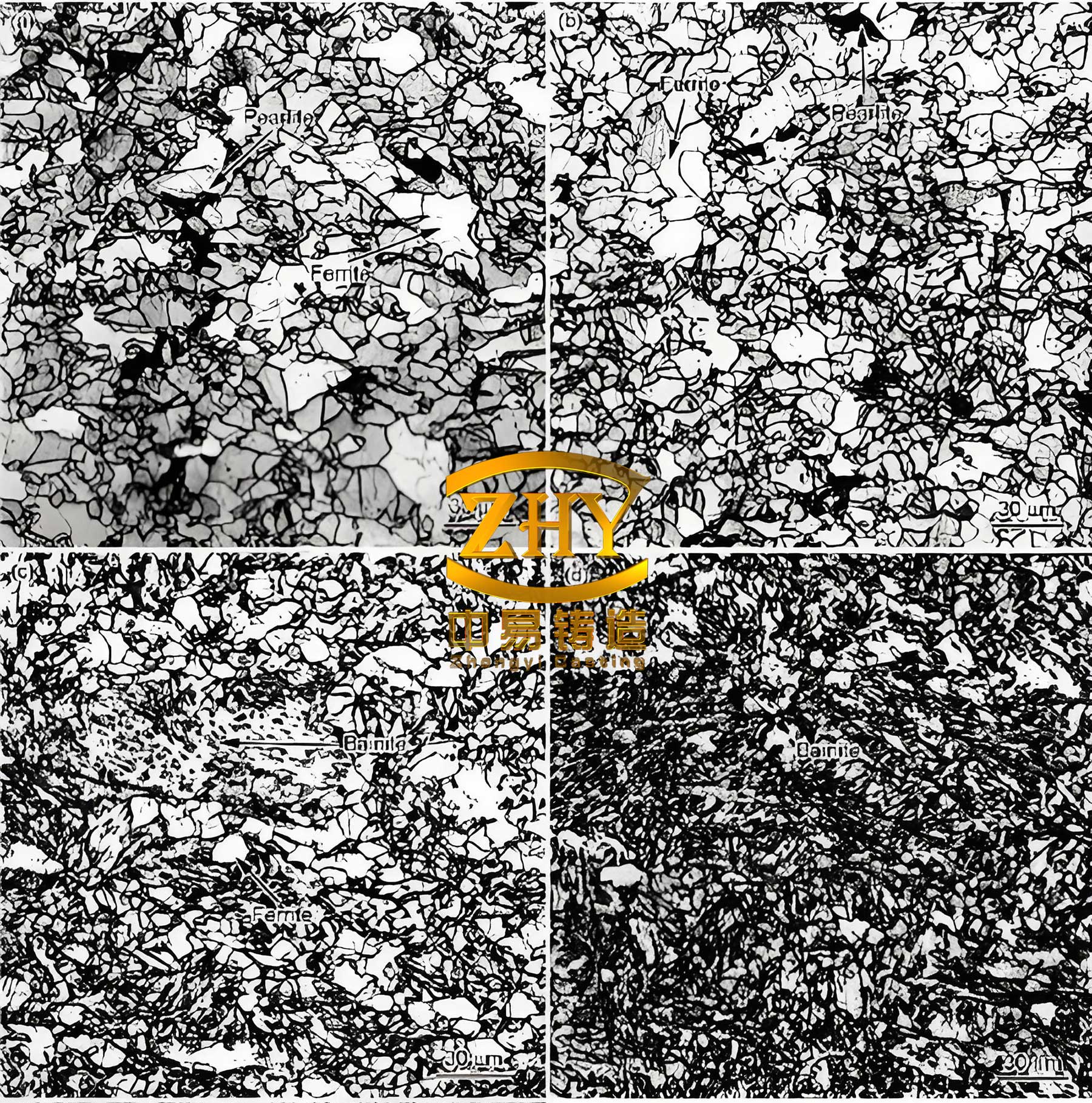
Metallographic samples were extracted from the castings to evaluate the microstructure. The analysis revealed a matrix consisting predominantly of fine pearlite (approximately 80%) with a small amount of ferrite. The graphite was present in a well-formed spheroidal morphology with a nodularity rating of 85% and a size rating of 6 (ASTM A247), as required for high-strength grades. This microstructure is the foundation for the excellent mechanical properties of spheroidal graphite cast iron. The relationship between yield strength and microstructure can be broadly described by a Hall-Petch type relationship, where strength increases with finer pearlite interlaminar spacing and a higher pearlite fraction:
$$ \sigma_y = \sigma_0 + k_p \cdot (V_p)^{1/2} + k_{s} \cdot (S)^{-1/2} $$
where $\sigma_y$ is the yield strength, $\sigma_0$ is a friction stress, $k_p$ and $k_s$ are constants, $V_p$ is the pearlite volume fraction, and $S$ is the interlamellar spacing.
Experimental Validation: Static and Fatigue Performance
To validate the FEA predictions and confirm the performance of the spheroidal graphite cast iron thrust rod, a series of physical tests were conducted.
1. Mechanical Property Testing: Tensile test bars were machined from the ball socket region of the castings. The results, averaged over three samples, confirmed that the material met the QT700-6 specification.
| Sample | Tensile Strength, $R_m$ (MPa) | Yield Strength, $R_{p0.2}$ (MPa) | Elongation, $A$ (%) | Hardness (HBW) |
|---|---|---|---|---|
| 1 | 765 | 440 | 6.9 | 253 |
| 2 | 780 | 443 | 7.2 | 249 |
| 3 | 748 | 434 | 6.7 | 259 |
| Average | 764 | 439 | 6.9 | 254 |
2. Static Bench Test: A full assembly was mounted on a multi-channel test rig. Strain gauges were attached at nine strategic locations on the rod’s surface. The rod was subjected to a quasi-static tensile load of +150 kN followed by a compressive load of -150 kN. The measured strain ($\epsilon$) was converted to stress ($\sigma$) using Hooke’s Law for uniaxial stress: $\sigma = E \cdot \epsilon$, with $E = 178$ GPa for the spheroidal graphite cast iron. The experimental stresses were then compared to the FEA-calculated stresses at the identical node locations. The comparison showed good correlation, with the error for most measurement points falling within an acceptable engineering margin of 15%.
| Gauge Point | Under Tensile Load (150 kN) | Under Compressive Load (150 kN) | ||
|---|---|---|---|---|
| Exp. Stress (MPa) | FEA Stress (MPa) | Exp. Stress (MPa) | FEA Stress (MPa) | |
| 1 | 134.8 | 115.3 | 101.1 | 78.9 |
| 2 | 83.3 | 75.2 | 74.9 | 79.9 |
| 3 | 89.2 | 81.8 | 62.7 | 71.6 |
| 4 | 16.0 | 14.4 | 27.4 | 24.1 |
| 5 | 81.2 | 75.4 | 84.6 | 76.8 |
| 6 | 96.8 | 85.7 | 95.4 | 85.7 |
| 7 | 80.3 | 75.2 | 79.0 | 85.8 |
| 8 | 10.9 | 12.3 | 8.3 | 9.8 |
| 9 | 92.0 | 83.3 | 71.6 | 80.5 |
3. Fatigue Durability Test: The most critical validation is fatigue life. Three spheroidal graphite cast iron thrust rod assemblies were subjected to a high-cycle fatigue test on a servo-hydraulic test system. A fully reversed sinusoidal load of ±150 kN was applied along the longitudinal axis at a frequency of 1.5 Hz. The test was run for 200,000 cycles, a standard benchmark for such components. The stiffness of the assembly (load/displacement) was monitored, and its change was required to remain below 20%. All three test specimens successfully completed the 200,000-cycle regimen without failure or significant stiffness degradation.
| Specimen ID | Load (kN) | Cycles | Stiffness Change | Result |
|---|---|---|---|---|
| #1 | ±150 | 200,000 | +11.8% | Pass |
| #2 | ±150 | 200,000 | +16.1% | Pass |
| #3 | ±150 | 200,000 | +9.4% | Pass |
The fatigue strength of spheroidal graphite cast iron can be related to its tensile strength and the stress concentration factor ($K_t$) of the design. For high-cycle fatigue under fully reversed loading ($R = -1$), an estimate of the endurance limit ($\sigma_e$) for ferrous materials is often given as a fraction of the tensile strength. For spheroidal graphite cast iron, a common approximation is $\sigma_e \approx 0.4 \cdot R_m$. Considering the maximum operational stress from FEA (287.4 MPa) and the material’s estimated endurance limit ($\approx 0.4 \times 764 \text{ MPa} = 305.6 \text{ MPa}$), the design demonstrates a positive margin against high-cycle fatigue under the tested conditions, corroborated by the successful bench test. The relationship is expressed as:
$$ \sigma_{max, service} < \sigma_e = C \cdot R_m $$
where $C$ is a coefficient typically between 0.35 and 0.45 for spheroidal graphite cast iron.
Conclusion
This development project successfully demonstrates the feasibility and advantages of utilizing monolithic spheroidal graphite cast iron for commercial vehicle V-shape thrust rods. The innovative H-beam integrated design achieves a 9% mass reduction compared to traditional fabricated steel assemblies. Comprehensive finite element analysis confirmed that the spheroidal graphite cast iron component experiences significantly lower peak stresses across all critical load cases. The manufacturing process utilizing as-cast QT700-6 spheroidal graphite cast iron is streamlined, cost-effective, and yields components with excellent microstructural integrity and mechanical properties. Experimental validation through static strain measurement showed good correlation with FEA models, and, most importantly, rigorous fatigue durability testing proved the component’s capability to withstand demanding service conditions for extended cycles without failure. This work establishes a strong case for the adoption of “cast-for-integration” strategies using high-performance spheroidal graphite cast iron in automotive structural applications, contributing simultaneously to lightweighting, performance, and cost-efficiency goals.