
In my investigation of mechanical component failures, I have encountered numerous cases involving shafts, which are critical for transmitting motion, torque, or bending moments in equipment. The fracture of a driving shaft can lead to significant downtime and safety hazards. Recently, I analyzed a failure incident involving a spheroidal graphite iron driving shaft from a screw refrigeration compressor. This shaft, made of spheroidal graphite iron grade QT700-2 with a diameter of 150 mm and length of 2000 mm, fractured during operation, causing equipment shutdown. To ensure safe production and prevent recurrence, I conducted a comprehensive failure analysis using various techniques, including macro morphology examination, chemical composition analysis, metallographic microstructure observation, mechanical property testing, and scanning electron microscopy (SEM) micro-morphology analysis. The goal was to identify the root cause and propose improvements. Spheroidal graphite iron is widely used for its good mechanical properties, but its performance heavily depends on microstructure control. In this article, I will detail my findings and insights, emphasizing the importance of microstructure in spheroidal graphite iron components.
My analysis began with a macroscopic examination of the fractured shaft. The fracture surface showed significant wear, but from unworn areas, I observed a rough texture with no macroscopic plastic deformation, indicating brittle material behavior. Distinct beach marks and chevron patterns were visible, suggesting that the fracture originated at the outer surface of the shaft and propagated inward. The presence of these features led me to preliminarily classify the failure as fatigue fracture, specifically torsional fatigue fracture, given the twisting痕迹 in the patterns. This aligns with common failure modes in shafts subjected to cyclic loading. The macroscopic evidence highlighted the need for deeper microstructural investigation to understand the initiation mechanisms.
To quantify the material composition, I performed chemical analysis using a direct reading spectrometer. Samples were taken from both the outer surface and core of the spheroidal graphite iron driving shaft. The results are summarized in Table 1. All elements, including carbon (C), silicon (Si), manganese (Mn), phosphorus (P), and sulfur (S), were within the standard ranges for spheroidal graphite iron, indicating that the material met general compositional specifications. However, composition alone does not guarantee performance; microstructure plays a pivotal role in determining properties like strength and fatigue resistance. The consistent composition between surface and core suggested that the issue might stem from processing rather than material chemistry.
| Sample Location | C | Si | Mn | P | S |
|---|---|---|---|---|---|
| Outer Surface | 3.850 | 2.540 | 0.650 | 0.021 | 0.001 |
| Core | 3.840 | 2.630 | 0.690 | 0.018 | 0.001 |
| Standard Range for Spheroidal Graphite Iron | 3.600-3.900 | 2.000-2.800 | 0.600-0.800 | <0.100 | <0.070 |
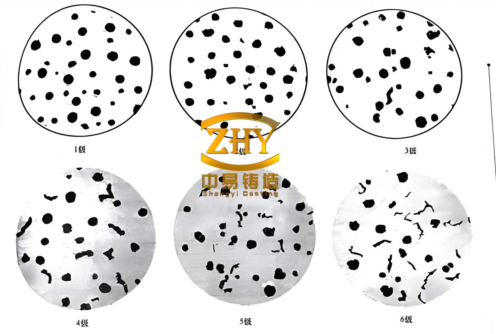
Next, I focused on the metallographic microstructure, which is crucial for understanding the behavior of spheroidal graphite iron. I prepared samples by sectioning the shaft near the crack initiation zone, followed by polishing and etching with a 4% nitric alcohol solution for 5 seconds. Under optical microscopy, the unetched samples revealed graphite morphology: predominantly spherical graphite with some vermicular or flake-like graphite. Notably, the outer surface exhibited significantly fewer graphite nodules compared to the interior, which I attributed to rapid cooling during casting that hindered proper graphite nucleation and growth. This scarcity of graphite at the surface can alter local mechanical properties, as graphite acts as a stress reliever in spheroidal graphite iron.
Upon etching, the microstructure became clearer. The matrix consisted primarily of pearlite, with a network of secondary cementite (appearing as white networks) surrounding the graphite nodules. This network was particularly pronounced at the outer surface, where graphite distribution was sparse. In spheroidal graphite iron, ideal microstructures feature well-dispersed spherical graphite in a matrix of pearlite or ferrite, but the presence of continuous cementite networks can embrittle the material. I quantified this effect using microhardness testing, with results shown in Table 2. The outer surface had an average hardness of 423 HV2N, while the core averaged 397 HV2N. This surface hardening, due to higher carbon content in the matrix from reduced graphite, increased brittleness and created favorable conditions for crack initiation. The hardness difference can be modeled using a linear relationship: $$ \Delta H = k \cdot (C_{surface} – C_{core}) $$ where $\Delta H$ is the hardness difference, $k$ is a material constant, and $C$ represents carbon content in the matrix. For spheroidal graphite iron, such gradients often stem from cooling rate variations during solidification.
| Location | Hardness Measurements (HV2N) | Average Hardness (HV2N) |
|---|---|---|
| Outer Surface | 432, 423, 419, 421, 420 | 423 |
| Core | 389, 390, 399, 410, 397 | 397 |
To assess bulk mechanical properties, I conducted tensile tests on specimens taken longitudinally from the shaft, at a distance of one-quarter diameter from the surface. The results, compared to the standard for QT700-2 spheroidal graphite iron, are presented in Table 3 and Figure 1. The average tensile strength was 525 MPa, yield strength was 379 MPa, and elongation was 4.7%, all below the standard requirements of 700 MPa tensile strength, 420 MPa yield strength, and 2% elongation. This deficiency in strength further corroborated the microstructural issues. The stress-strain curve exhibited limited plasticity, typical of brittle materials with microstructural defects. The reduced strength can be expressed by a modified rule of mixtures for spheroidal graphite iron: $$ \sigma_{composite} = V_g \cdot \sigma_g + V_m \cdot \sigma_m – \sigma_{defect} $$ where $\sigma_{composite}$ is the composite strength, $V_g$ and $V_m$ are volume fractions of graphite and matrix, $\sigma_g$ and $\sigma_m$ are their respective strengths, and $\sigma_{defect}$ accounts for strength loss due to defects like cementite networks. In this case, the high $V_m$ with embrittling phases increased $\sigma_{defect}$, lowering overall strength.
| Sample | Tensile Strength (MPa) | Yield Strength (MPa) | Elongation (%) |
|---|---|---|---|
| 1 | 512 | 381 | 4.1 |
| 2 | 510 | 377 | 4.2 |
| 3 | 554 | 380 | 5.9 |
| Average | 525 | 379 | 4.7 |
| QT700-2 Standard | 700 | 420 | 2.0 |
For a detailed fracture analysis, I used scanning electron microscopy (SEM) to examine the micro-morphology of the fracture surface. The SEM images revealed distinct fatigue striations in local areas, confirming the fatigue fracture mechanism. Additionally, intergranular fracture features were observed, indicating that the networked cementite at the surface facilitated crack propagation along grain boundaries. Energy-dispersive X-ray spectroscopy (EDS) analysis on the matrix showed primarily iron (95.31%) and silicon (4.69%), with no significant sulfur or phosphorus, ruling out impurity-induced embrittlement. The fatigue process in spheroidal graphite iron can be described by the Paris law for crack growth: $$ \frac{da}{dN} = C (\Delta K)^m $$ where $da/dN$ is the crack growth rate per cycle, $\Delta K$ is the stress intensity factor range, and $C$ and $m$ are material constants. The presence of microstructural defects like cementite networks likely increased $C$, accelerating crack growth and reducing fatigue life.
Based on my findings, I concluded that the fracture was a torsional fatigue failure initiated at the outer surface of the spheroidal graphite iron driving shaft. The root cause was the inferior microstructure at the surface: sparse graphite distribution and a networked secondary cementite phase. This led to increased brittleness and hardness, creating stress concentrators that served as fatigue crack initiation sites. The mechanical properties fell below standard due to these microstructural anomalies. In spheroidal graphite iron, optimal performance requires uniform graphite dispersion and minimal continuous brittle phases. The fatigue life $N_f$ can be estimated using the Basquin equation: $$ N_f = \left( \frac{\sigma_a}{\sigma_f’} \right)^{-b} $$ where $\sigma_a$ is the stress amplitude, $\sigma_f’$ is the fatigue strength coefficient, and $b$ is the fatigue exponent. For this shaft, the reduced $\sigma_f’$ from microstructural defects decreased $N_f$, leading to premature failure.
To prevent such failures in spheroidal graphite iron components, I recommend several improvements in the manufacturing process. First, during casting, controlling the cooling rate is essential to promote uniform graphite nucleation. Increasing mold temperature and adjusting pouring parameters can mitigate surface chilling. Second, heat treatment processes like annealing should be optimized to dissolve cementite networks and improve microstructure homogeneity. For instance, a subcritical anneal at temperatures below the eutectoid can help spheroidize cementite. Third, surface treatments such as shot peening or induction hardening can be applied after machining to introduce compressive residual stresses, enhancing fatigue resistance. The effectiveness of shot peening can be quantified by the induced stress depth $d$: $$ d = k_p \cdot \frac{E}{\sigma_y} $$ where $k_p$ is a peening constant, $E$ is Young’s modulus, and $\sigma_y$ is the yield strength. Lastly, stringent quality control, including non-destructive testing and microstructure inspection, should be implemented for spheroidal graphite iron shafts to ensure compliance with standards.
In summary, my analysis underscores the critical role of microstructure in the performance of spheroidal graphite iron driving shafts. The failure was driven by surface microstructural defects that embrittled the material and predisposed it to fatigue crack initiation. By addressing these issues through process optimization and quality assurance, the reliability of spheroidal graphite iron components can be significantly enhanced. Future work could involve finite element modeling to simulate stress distributions and fatigue life in spheroidal graphite iron shafts with varying microstructures, further refining design and manufacturing guidelines. Through such efforts, the durability and safety of mechanical systems relying on spheroidal graphite iron can be assured.