
The presence of non-metallic inclusions, primarily in the form of slag inclusion defects, remains one of the most pervasive and detrimental quality issues in foundry practice. As a casting engineer or researcher, I have observed firsthand how these inclusions act as potent stress concentrators, severely degrading the mechanical properties of cast components. They are notorious initiators of fatigue cracks and can lead to catastrophic failures under dynamic loading conditions, undermining the structural integrity and service life of critical parts. Therefore, the pursuit of effective methods to minimize slag inclusion is not merely an academic exercise but a fundamental requirement for producing reliable, high-performance castings.
The battle against slag inclusion begins long before the metal enters the mold cavity. It involves meticulous melt treatment and slag removal practices. However, the final and often most critical line of defense is the gating system. A well-designed gating system does more than just convey molten metal; it must act as a filter and a settling tank, strategically manipulating the flow to trap and retain slag particles before they can be entrained into the casting itself. The core challenge lies in understanding the complex interplay between the fluid dynamics of the flowing metal and the trajectory of suspended slag particles. This understanding allows us to design gating systems that promote the separation of these phases.
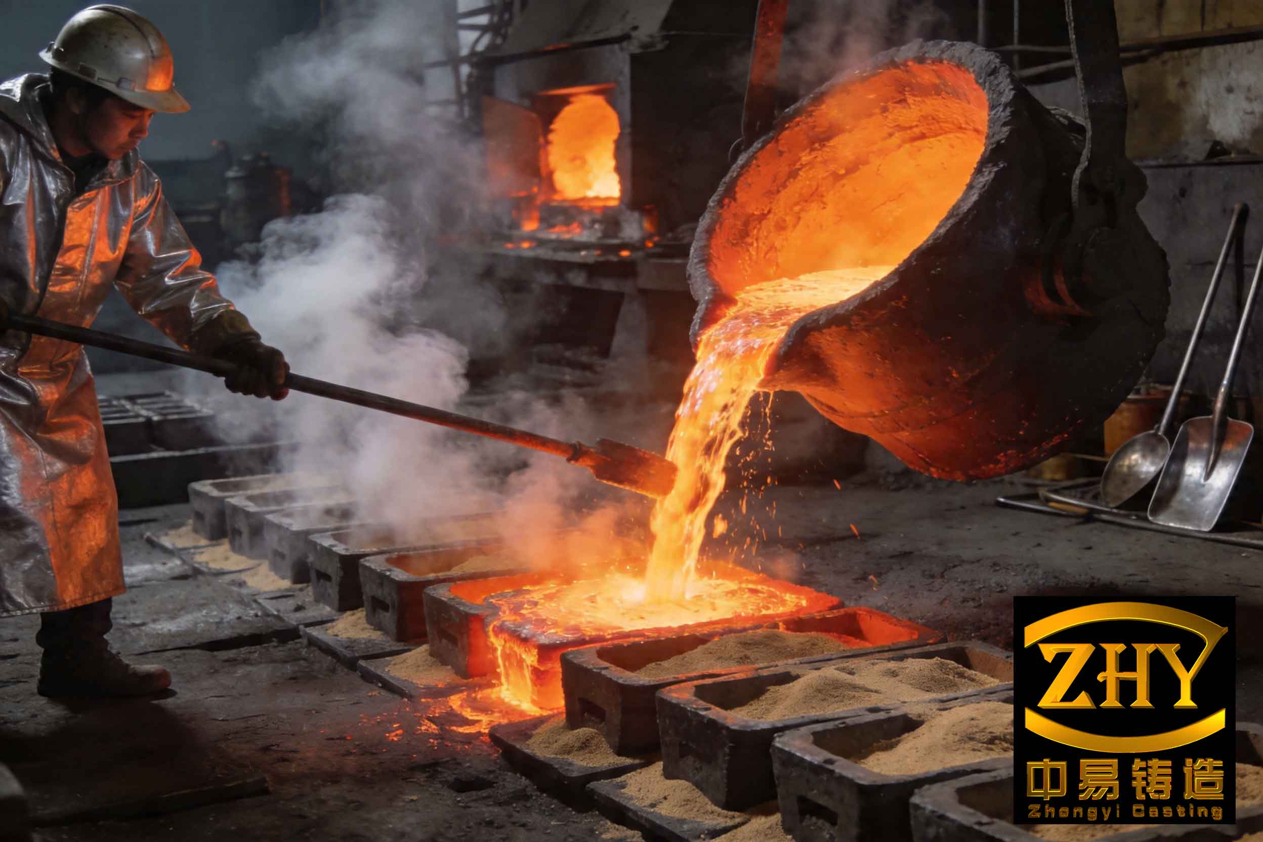
The visual evidence of a slag inclusion defect, as shown, underscores the severity of the problem. To combat this, we must move beyond trial-and-error methods. Modern computational tools enable us to simulate the entire filling process, providing unparalleled insight into how slag particles move. One powerful approach is the use of a Dispersed Phase Particle Model (DPM). In this model, the molten metal is treated as a continuous fluid (the primary phase), while the slag particles are treated as a discrete, secondary phase whose motion is tracked individually. The trajectory of a slag particle is governed by the forces acting upon it, primarily drag from the surrounding fluid and buoyancy due to density difference.
The fundamental fluid flow is described by the Navier-Stokes equations for conservation of mass and momentum:
$$ \frac{\partial \rho}{\partial t} + \nabla \cdot (\rho \mathbf{u}) = 0 $$
$$ \frac{\partial (\rho \mathbf{u})}{\partial t} + \nabla \cdot (\rho \mathbf{u} \mathbf{u}) = -\nabla p + \nabla \cdot \boldsymbol{\tau} + \rho \mathbf{g} $$
where $\rho$ is the fluid density, $\mathbf{u}$ is the velocity vector, $p$ is pressure, $\boldsymbol{\tau}$ is the stress tensor, and $\mathbf{g}$ is gravitational acceleration. The motion of a discrete slag particle is calculated by integrating the force balance equation:
$$ m_p \frac{d\mathbf{u}_p}{dt} = \mathbf{F}_D + \mathbf{F}_g + \mathbf{F}_b $$
where $m_p$ and $\mathbf{u}_p$ are the mass and velocity of the particle. The dominant forces are the drag force $\mathbf{F}_D$, the gravitational force $\mathbf{F}_g$, and the buoyancy force $\mathbf{F}_b$. For small, spherical particles in a turbulent flow, the drag force can be expressed as:
$$ \mathbf{F}_D = \frac{1}{2} C_D \rho A_p |\mathbf{u} – \mathbf{u}_p| (\mathbf{u} – \mathbf{u}_p) $$
Here, $C_D$ is the drag coefficient, and $A_p$ is the projected area of the particle. The buoyancy force is given by $\mathbf{F}_b = -V_p \rho \mathbf{g}$, where $V_p$ is the particle volume. The key insight is that for a particle to be separated, the net effect of buoyancy must allow it to migrate out of the main flow stream before being carried into the casting. The effectiveness of any gating feature in promoting slag inclusion removal hinges on its ability to create flow conditions that maximize this separation.
Key Principles for Slag-Trapping Gating Design
Based on extensive simulation and experimental validation, several core principles emerge for designing gating systems that effectively mitigate slag inclusion. These principles focus on controlling velocity, direction, and time to allow natural separation mechanisms to work.
Principle 1: Velocity Reduction and Flow Laminarization
The single most important factor is controlling metal velocity. High velocity creates turbulent flow, which keeps slag particles in suspension and dramatically increases the likelihood of slag inclusion. The primary function of the sprue and runner is to decelerate the flow. A common design rule is to use a tapered sprue to prevent aspiration and then expand the cross-sectional area into the runner. This expansion, governed by the continuity equation ($A_1 v_1 = A_2 v_2$), directly reduces flow velocity ($v$), allowing inertial forces on particles to diminish and buoyancy to become more influential.
Principle 2: Strategic Use of Runner Geometry
The runner is the main channel for slag separation. A horizontal, straight runner located in the drag half of the mold is superior to vertical or branched designs. The horizontal orientation allows buoyant particles to rise to the top surface of the runner. The length of the runner is critical—it provides the necessary residence time for particles to float up. The required minimum length ($L_{min}$) can be estimated based on the particle’s terminal rise velocity ($v_t$) and the metal flow velocity in the runner ($v_{runner}$):
$$ L_{min} = \frac{H_{runner} \cdot v_{runner}}{v_t} $$
where $H_{runner}$ is the runner height. This shows that for a given runner height, slower flow or faster particle rise allows for a shorter runner, but in practice, longer runners are generally more effective for slag inclusion control.
Principle 3: Incorporation of Active Slag Traps
Beyond passive runners, active traps are designed features that create localized flow conditions ideal for slag removal. The main types are:
- Runner Extension (Pouring Basin/Sprue Well): A chamber at the base of the sprue that absorbs the initial impact of the metal stream, dissipating energy and allowing the first, often dirtiest, metal to deposit its slag.
- Strainer Cores: Physical ceramic filters placed in the runner that mechanically intercept slag particles. They are highly effective but add cost and can chill the metal.
- Whirl Gate (Centrifugal Separator): An exceptionally effective design. Metal is introduced tangentially into a circular chamber, creating a vortex. Centrifugal force ($F_c = m_p \omega^2 r$) throws denser metal to the periphery, while less dense slag particles are forced toward the center, where they coalesce and float to the top of a central riser. This is one of the most reliable methods for preventing slag inclusion.
- Damming or Step Gates: These create a vertical step in the runner. The metal must flow over the dam, causing a change in direction. Slag particles, floating on the surface, are trapped behind the dam as the cleaner metal from the lower portion of the runner flows over it.
Comparative Analysis of Gating System Performance
To quantify the impact of design, let’s analyze several gating system configurations for a hypothetical aluminum alloy casting. We assume a constant number of slag particles (e.g., 20,000) of a given size and density are introduced with the metal. The performance is evaluated by the system’s Slag Removal Efficiency (SRE), defined as the percentage of particles trapped in the gating system and risers before entering the casting cavity.
The following table summarizes the key design parameters and expected performance outcomes for four distinct gating system layouts, ranging from a simple design to an optimized, slag-trapping system.
| Gating System Design | Key Features | Flow Characteristic | Primary Slag Removal Mechanism | Estimated Slag Removal Efficiency (SRE) | Relative Complexity/Cost |
|---|---|---|---|---|---|
| Type A: Open, Vertical Branching | Un-tapered sprue, multiple vertical gates branching directly into casting. | High velocity, highly turbulent, direct impingement. | Minimal. Relies only on buoyancy in casting cavity. | Low (20-35%) | Low |
| Type B: Semi-Closed, Straight Horizontal Runner | Tapered sprue, single horizontal runner, multiple ingates from top of runner. | Moderate velocity in runner, more laminar flow in runner. | Buoyancy in extended horizontal runner; surface skimming. | Medium (50-70%) | Medium |
| Type C: Semi-Closed with Runner Extension & Dam | Tapered sprue, deep sprue well, horizontal runner with a dam before the ingates. | Low velocity in runner, quiescent zone behind dam. | Energy dissipation in sprue well; damming traps surface slag. | High (75-85%) | Medium-High |
| Type D: Semi-Closed with Whirl Gate | Tapered sprue, horizontal runner leading to tangential whirl gate chamber. | Controlled vortex in whirl chamber; very calm flow exiting to casting. | Centrifugal separation in whirl chamber; central slag collection riser. | Very High (85-95%+) | High |
The data clearly indicates that system complexity and cost increase with SRE. However, the reduction in scrap rates and improvement in casting reliability often justify the investment in more advanced designs like Type C or D for critical components where slag inclusion is unacceptable.
Quantitative Modeling of Particle Trajectory and Separation
The decision for a specific design can be supported by modeling the particle trajectory. The terminal rise velocity ($v_t$) of a slag particle in a quiet liquid, crucial for determining required settling times, is derived from Stokes’ law for small, spherical particles at low Reynolds numbers:
$$ v_t = \frac{g d_p^2 (\rho_m – \rho_s)}{18 \mu} $$
where $d_p$ is the particle diameter, $\rho_m$ and $\rho_s$ are the density of the metal and slag respectively, and $\mu$ is the dynamic viscosity of the metal. In a flowing runner, the actual upward velocity is influenced by the vertical velocity profile of the metal. A particle’s trajectory is a vector sum of the horizontal drag velocity ($u_{drag}$) and its vertical rise velocity relative to the fluid. For effective separation, the particle must reach the top of the runner before it travels the length of the runner to the ingate. This creates a “separation criterion”:
$$ \text{Time to float to top: } t_{float} = \frac{H_{runner}}{v_t} $$
$$ \text{Time to reach ingate: } t_{travel} = \frac{L_{runner}}{u_{drag}} $$
For separation: $t_{float} < t_{travel}$. Therefore:
$$ L_{runner} > \frac{u_{drag} \cdot H_{runner}}{v_t} $$
This inequality provides a direct mathematical basis for sizing the runner length. For example, with a runner height of 15 mm, a metal velocity of 0.5 m/s, and a particle rise velocity of 0.01 m/s, the runner must be longer than 0.75 meters to allow that particle to surface. This explains why short runners are ineffective against slag inclusion.
Advanced Optimization and Simulation Workflow
The modern approach to eliminating slag inclusion involves an integrated simulation and optimization loop:
- Base Geometry Setup: A 3D CAD model of the casting and initial gating concept is created.
- Multi-Phase Flow Simulation: A filling simulation is run using VOF (Volume of Fluid) or similar methods to establish the fluid flow pattern, pressure, and velocity fields.
- Discrete Phase Simulation: Using the flow field from step 2, a DPM simulation is conducted. Thousands of virtual slag particles with a defined size distribution (e.g., following a Rosin-Rammler distribution) are injected at the pour point. Their paths are tracked, and final locations (trapped in gate, entrapped in casting) are recorded.
- Analysis and Redesign: The simulation results are analyzed. Areas of high particle concentration in the casting indicate potential slag inclusion sites. The gating geometry is then modified—lengthening the runner, adding a dam, or incorporating a whirl gate—to alter the flow and improve particle trajectory.
- Iteration: Steps 2-4 are repeated until the simulated slag inclusion rate in the casting falls below an acceptable threshold.
The final design parameters from such an optimization for an aluminum wheel casting might look like the values in the following table, balancing fluid dynamics with practical mold-making considerations.
| Parameter | Symbol | Optimized Value | Design Rationale |
|---|---|---|---|
| Sprue Base Diameter | $D_s$ | 40 mm | Provides sufficient flow area to minimize aspiration and initial velocity. |
| Runner Cross-Section (Drag) | $A_r$ | Height: 20 mm, Width: 30 mm | Increases area vs. sprue base to reduce velocity; sufficient depth for slag accumulation. |
| Minimum Runner Length | $L_{r,min}$ | 800 mm | Calculated from separation criterion to ensure 100-micron particles have time to float. |
| Whirl Gate Chamber Diameter | $D_w$ | 100 mm | Provides sufficient diameter to develop stable vortex for effective centrifugal separation. |
| Ingate Cross-Section Area (Total) | $\Sigma A_i$ | 1.2 x Sprue Base Area | Slightly larger to ensure runner remains full and pressurised, preventing air aspiration. |
| Ingate Thickness | $t_i$ | 4 mm | Thin enough to promote easy breaking-off and minimize turbulence in cavity. |
Conclusion and Future Perspectives
The control of slag inclusion defects is fundamentally an exercise in applied fluid dynamics and proactive design. A passive gating system that merely conveys metal will invariably lead to casting quality issues. The key to success lies in intentionally designing the gating system to manage energy and flow direction. The universal principles are velocity reduction, flow laminarization, provision of sufficient residence time and distance for separation, and the strategic use of active trapping mechanisms like dams and centrifugal whirl gates. As simulation technology advances, the ability to accurately model discrete particle trajectories provides a powerful tool for virtual prototyping and optimization, moving gating design from an art to a precise science. The ultimate goal is a zero-defect process where slag inclusion is designed out at the pattern stage, ensuring the production of clean, reliable, and high-integrity castings.