
In our foundry, we have long specialized in the production of ductile iron castings for critical machinery components. Among these, crankshafts for expanders used in oxygen generation systems are particularly demanding due to their high-strength requirements and the necessity for flawless surfaces after precision machining. For years, we struggled with a persistent quality issue: the occurrence of micro-slag inclusions on the machined surfaces of these crankshafts. These defects, often appearing as dark, non-metallic spots upon magnetic particle inspection, led to rejection rates as high as 30%, severely impacting production schedules and overall product reliability. The defect was identified as slag inclusion, a common yet detrimental flaw in casting processes. This article details our comprehensive analysis of the root causes and the systematic engineering improvements we implemented to entirely eliminate slag inclusion from our ductile iron crankshafts, achieving near-zero defect rates and stable production.
The crankshafts are manufactured from high-grade ductile iron, specifically a grade equivalent to QT600-3, which offers an excellent combination of strength and ductility. The casting process must ensure not only mechanical properties but also supreme internal and surface quality. The initial, or “old,” process involved horizontal molding and horizontal pouring (often termed “flat” pouring). A single mold contained two crankshafts. The gating system, while incorporating elements like a pouring basin gate and a strainer core for slag trapping, proved inadequate. The fundamental flaw lay in the orientation and thermal dynamics of the process. Horizontal pouring created a large, flat upper surface area within the mold cavity. This configuration is inherently poor for the escape of gases and the flotation of slag particles. Despite careful skimming of the molten iron before pouring, microscopic slag particles suspended in the melt were carried into the cavity and, due to buoyancy, settled on the upper surfaces and dead corners of the casting. The phenomenon of slag inclusion formation is governed by principles of fluid dynamics and thermodynamics, which we can summarize with key relationships.
The velocity at which a slag particle rises (or sinks) in molten iron can be described by Stokes’ law for small spherical particles in a viscous fluid:
$$v = \frac{2 r^2 ( \rho_f – \rho_s ) g}{9 \eta}$$
Where \( v \) is the terminal velocity (m/s), \( r \) is the radius of the slag particle (m), \( \rho_f \) is the density of molten iron (approximately 7000 kg/m³), \( \rho_s \) is the density of the slag (approximately 2500-3000 kg/m³), \( g \) is the acceleration due to gravity (9.81 m/s²), and \( \eta \) is the dynamic viscosity of the molten iron (Pa·s). A critical insight from this equation is that the flotation velocity is inversely proportional to viscosity. In our old process, the pouring temperature was maintained at a relatively low 1320-1340°C. At these temperatures, the viscosity of ductile iron is higher, significantly reducing \( v \) and impeding the ability of slag particles to float to the top of the mold cavity before the metal solidifies. This directly promoted slag inclusion retention within the casting wall. Furthermore, lower pouring temperatures increase the tendency for surface oxidation and the formation of oxide films (dross) on the flowing metal stream. These films, once fragmented and entrained, become a primary source of exogenous slag inclusion.
The design of the original gating system exacerbated the problem. It was complex and promoted turbulent flow, preventing calm and sequential filling of the mold. Turbulence increases the re-entrainment of any slag that might have initially floated. Moreover, the cross-sectional area ratios of the gating system were unbalanced. The choke was placed after the runner, and the system was overly open toward the casting. The gating ratio (sprue:runner:ingate) was approximately 1 : 2.5 : 3. This design failed to pressurize the system effectively, allowing the initial, cooler, and often slag-laden portion of the iron to enter the cavity first. The risers, positioned conventionally, could not act as effective slag traps because they were not integrated into the filling sequence to receive this initial flow. The table below summarizes the key parameters and issues of the initial process that fostered slag inclusion defects.
| Process Parameter | Condition in Old Process | Impact on Slag Inclusion Formation |
|---|---|---|
| Pouring Orientation | Horizontal mold, horizontal pour | Large horizontal top surface impedes slag flotation and gas evacuation. |
| Pouring Temperature | 1320 – 1340 °C | Higher viscosity reduces slag flotation velocity (per Stokes’ Law). Promotes dross formation. |
| Gating System Design | Complex, single-level, turbulent flow | Increases metal oxidation and slag entrainment during filling. |
| Gating Ratio (Sprue:Runner:Ingate) | ~1 : 2.5 : 3 | Unpressurized system allows cold, dirty metal to enter cavity first. |
| Riser Function | Only for feeding, not integrated into filling | Ineffective as a slag trap during the initial pour phase. |
| Mold Cavity Topography | Presence of upper dead corners | Traps floating slag particles, creating localized slag inclusion zones. |
The visual manifestation of these defects was critical for diagnosis. The slag inclusion appeared as finely dispersed, dark, and dull spots on the machined surface, predominantly in the upper regions of the casting.
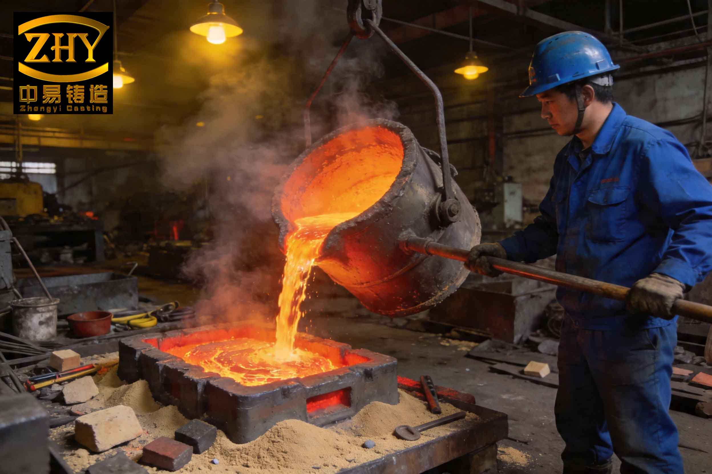
Understanding this, we embarked on a complete redesign of the casting process, targeting every factor that contributed to slag inclusion formation and retention.
The new, improved process is fundamentally different in its philosophy: control the thermal and flow conditions to minimize slag generation, promote its removal, and prevent its entrapment. The cornerstone change was shifting from a horizontal pour to a vertical pour within a horizontally oriented mold (often called “stacked” or “vertical gating”). The crankshafts are still molded horizontally for geometric convenience, but the metal is introduced from the bottom and rises vertically through the gating to fill the cavity. This immediately creates a favorable temperature gradient and directional solidification pattern. The key modifications are detailed below and summarized in a subsequent comparative table.
First, the pouring orientation was changed to a vertical gating system. This ensures that as the mold fills, the hottest metal rises, creating a natural temperature gradient that supports directional solidification from the bottom up. More importantly, any slag particles have a shorter, more direct path to float upwards into the risers, which are now strategically placed at the highest points. Second, a blind riser (or atmospheric riser) was placed at the top of each crankshaft’s main journal. This riser serves a dual purpose: it provides feed metal to compensate for shrinkage in the thick sections, and it acts as a perfect slag collection reservoir. As the cleanest, hottest metal enters the mold last and resides in the riser, any residual slag inclusion particles are buoyed into this reservoir and are safely isolated from the final casting.
Third, the gating system was redesigned as a three-step tapered runner with multiple ingates at different heights—a step-gating system. The lowest ingates fill the mold base, the middle ones ensure steady filling, and the topmost ingates direct the final, hottest iron directly into the blind risers. This sequential filling minimizes turbulence and ensures that the initial, potentially cooler and dirtier iron is largely contained within the lower parts of the gating system. Specifically, we incorporated small slag traps or “dirt traps” in the runner, just before the first ingates, to capture this initial flow. The flow dynamics can be partially modeled using the Bernoulli principle and continuity equation for incompressible flow:
$$P + \frac{1}{2} \rho v^2 + \rho g h = \text{constant}$$
$$Q = A_1 v_1 = A_2 v_2$$
Where \( P \) is pressure, \( \rho \) is density, \( v \) is flow velocity, \( g \) is gravity, \( h \) is height, \( Q \) is volumetric flow rate, and \( A \) is cross-sectional area. By carefully designing the cross-sectional areas (choke at the sprue base, expanding runners), we reduced flow velocity (\( v \)) in the cavity, minimizing turbulence and oxidation. The new gating ratio is a pressurized type, approximately 1 : 0.9 : 1.1, ensuring a rapid, filled-system flow that prevents air aspiration and dross formation.
Fourth, we significantly increased the pouring temperature to 1380-1400°C. Referring back to Stokes’ law, the dynamic viscosity \( \eta \) of molten iron decreases exponentially with temperature. A simplified empirical relation for ductile iron near the pouring range is:
$$ \eta \approx \eta_0 \exp\left(\frac{E_a}{RT}\right) $$
Where \( \eta_0 \) is a constant, \( E_a \) is the activation energy for viscous flow, \( R \) is the gas constant, and \( T \) is absolute temperature. A temperature increase from 1330°C to 1390°C (1603K to 1663K) can reduce viscosity by 20-30%. This dramatically increases the flotation velocity \( v \) of slag particles, giving them ample time to rise into the risers before solidification. Higher temperature also improves fluidity, allowing for a calmer fill and reducing the tendency for premature solidification that can trap slag.
Fifth, we introduced a sealed pouring basin with a stopper rod (a “tap pour” or “ladle gate”). This allows the molten iron to settle and any gross slag to separate in the pouring basin before the stopper is lifted. Only then does the clean metal enter the sprue, virtually eliminating the introduction of exogenous slag from the ladle stream. Finally, the vents were redesigned into curved channels to prevent sand from falling back into the cavity, which could be another source of non-metallic slag inclusion.
The table below provides a direct comparison between the old and new processes, highlighting the engineering changes made to combat slag inclusion.
| Aspect | Old Process | New Process | Mechanism for Slag Reduction |
|---|---|---|---|
| Pouring Orientation | Horizontal Pour | Vertical Gating (Horizontal Mold) | Creates favorable thermal gradient; directs slag flotation path to top risers. |
| Pouring Temperature | 1320-1340 °C | 1380-1400 °C | Lowers viscosity, increases slag flotation speed per Stokes’ Law; reduces dross. |
| Gating System | Single-level, turbulent | Three-step step-gating with slag traps | Ensures sequential, calm filling; traps initial dirty metal; minimizes turbulence. |
| Gating Ratio | ~1 : 2.5 : 3 (Open) | ~1 : 0.9 : 1.1 (Pressurized) | Promotes rapid, filled-system flow, preventing air aspiration and oxidation. |
| Riser Design & Function | Conventional feeding riser | Blind riser at top + pressure riser between castings | Acts as effective hot slag collection reservoir; enhances feeding for soundness. |
| Pouring Method | Open stream from ladle | Stopper-controlled sealed pour basin | Allows metal settling and slag separation before entering mold. |
| Primary Slag Removal Mechanism | Passive flotation in flat cavity | Active flotation into designed slag traps (risers) | Systematically collects and isolates slag inclusion particles away from casting. |
The results of implementing this new process were immediate and sustained. The rejection rate due to slag inclusion dropped from over 30% to virtually zero. Magnetic particle inspection of machined crankshafts now consistently shows clean, defect-free surfaces. The internal soundness has also improved due to the better feeding from the top risers, leading to denser microstructure. The process has proven so robust that we have successfully applied the same principles—vertical gating, step pouring, high temperature, and strategic risering—to other crankshaft variants with different sizes and complexities, all showing elimination of slag inclusion defects.
To quantify the improvement, we can model the effectiveness of slag removal. The efficiency \( \epsilon \) of the riser as a slag trap can be conceptualized as the ratio of slag volume diverted to the riser versus the total slag volume entering the gating system. While difficult to measure directly, it correlates with the difference in flotation velocity and the available time \( t \) before solidification. The distance a particle can float is \( d = v \cdot t \). In the new process, with higher \( v \) (due to higher T) and a designed short distance \( d \) to the riser, almost all particles reach the trap. The solidification time \( t \) for a sand-cast section can be approximated by Chvorinov’s rule:
$$ t = B \left( \frac{V}{A} \right)^n $$
Where \( V \) is volume, \( A \) is surface area, \( B \) is a mold constant, and \( n \) is an exponent (often ~2). For our crankshaft, the modulus \( (V/A) \) is relatively large, granting sufficient time \( t \) for slag flotation in the new process, whereas in the old process, the low \( v \) meant particles could not traverse the horizontal distance in time, leading to trapped slag inclusion.
The battle against slag inclusion is multi-faceted. It requires control over metallurgical factors (composition, temperature), physical design (gating, risering), and procedural steps (pouring technique). Our experience underscores that simply adding filters or slag traps in an ill-conceived system is insufficient. A holistic approach that optimizes the entire fluid and thermal pathway is essential. The formation of slag inclusion can be seen as a race between the flotation time of impurities and the solidification time of the metal. The process modifications we implemented are all geared towards winning this race for the slag particles, guiding them safely away from the final casting. Every aspect, from the poured stream to the last point of solidification, must be managed to prevent the entrapment of any non-metallic material that would manifest as a slag inclusion.
In conclusion, the complete elimination of slag inclusion defects in our ductile iron crankshafts was achieved not by a single silver bullet but through a systematic re-engineering of the casting process based on fundamental principles of fluid flow, heat transfer, and solidification. The shift to vertical gating with step pouring, combined with significantly higher pouring temperatures, pressurized gating design, and risers purpose-built as slag collectors, created a process inherently resistant to slag inclusion formation. This comprehensive strategy has transformed a high-rejection item into a reliably high-quality component, ensuring production stability and meeting the stringent requirements of precision machinery. The principles established here are universally applicable to the casting of any complex, high-integrity ductile iron component where slag inclusion poses a quality risk. Continuous vigilance and adherence to these optimized parameters are key to maintaining a defect-free output, fully suppressing the occurrence of slag inclusion in our foundry operations.