
My engagement with modern foundry practices, particularly concerning cupola melting and the production of high-integrity ductile iron castings, has provided significant insight into the persistent challenges and effective solutions within the industry. A primary focus, and a recurring obstacle to quality and yield, is the formation of slag inclusion defects. These defects manifest as non-metallic imperfections on the upper surfaces or cope sides of castings, severely compromising mechanical properties, pressure tightness, and overall reliability. This discussion synthesizes process principles, a detailed case study on defect elimination, and broader strategies for quality enhancement in iron founding.
The cupola furnace, despite the rise of electric melting, retains its relevance in specific production scenarios due to its efficiency and unique metallurgical characteristics. The key to its continued viability lies in technological upgrades aimed at improving melt quality and operational sustainability. Two notable process innovations I have observed involve in-furnace reduction reactions. The first is the successful incorporation of pelletized ore into the charge. Under appropriate kinetic conditions within the cupola, the iron oxides in the pellets are fully reduced, resulting in metallic iron yield and a slag with remarkably low FeO content, between 1% and 3%. This demonstrates the cupola’s capability for direct reduction when process parameters are meticulously controlled.
A second example is the in-furnace alloying of boron using the mineral colemainite (MgB2O3·3H2O). Added at the back of the cupola, the mineral dehydrates and decomposes in the preheating zone. The resulting B2O3 subsequently melts and is reduced at temperatures exceeding 1400°C by carbon and silicon present in the charge, forming boron and boron carbide which dissolve into the iron melt. This method, later replaced by ferroboron or dehydrated borax addition in induction furnaces for better control, highlights the historical flexibility of the cupola for certain alloying operations. The overarching path forward involves embracing competition and growth among various melting platforms—coke-based and gas-fired cupolas, induction furnaces, and rotary furnaces—while universally prioritizing advancements that lead to superior molten metal quality and environmental stewardship.
However, melting is only the beginning. The subsequent handling and casting of the metal, especially for sensitive alloys like ductile iron, are critical. Here, slag inclusion formation becomes a predominant concern. The defects originate from two main sources: primary slag (dross), comprising oxides of magnesium, silicon, and iron formed during treatment and pouring, and secondary slag, created by turbulent re-oxidation of the metal during mold filling. Entrapped slag appears as irregular, dark streaks or patches on machined surfaces, often located at the cope or near upper interior cores.
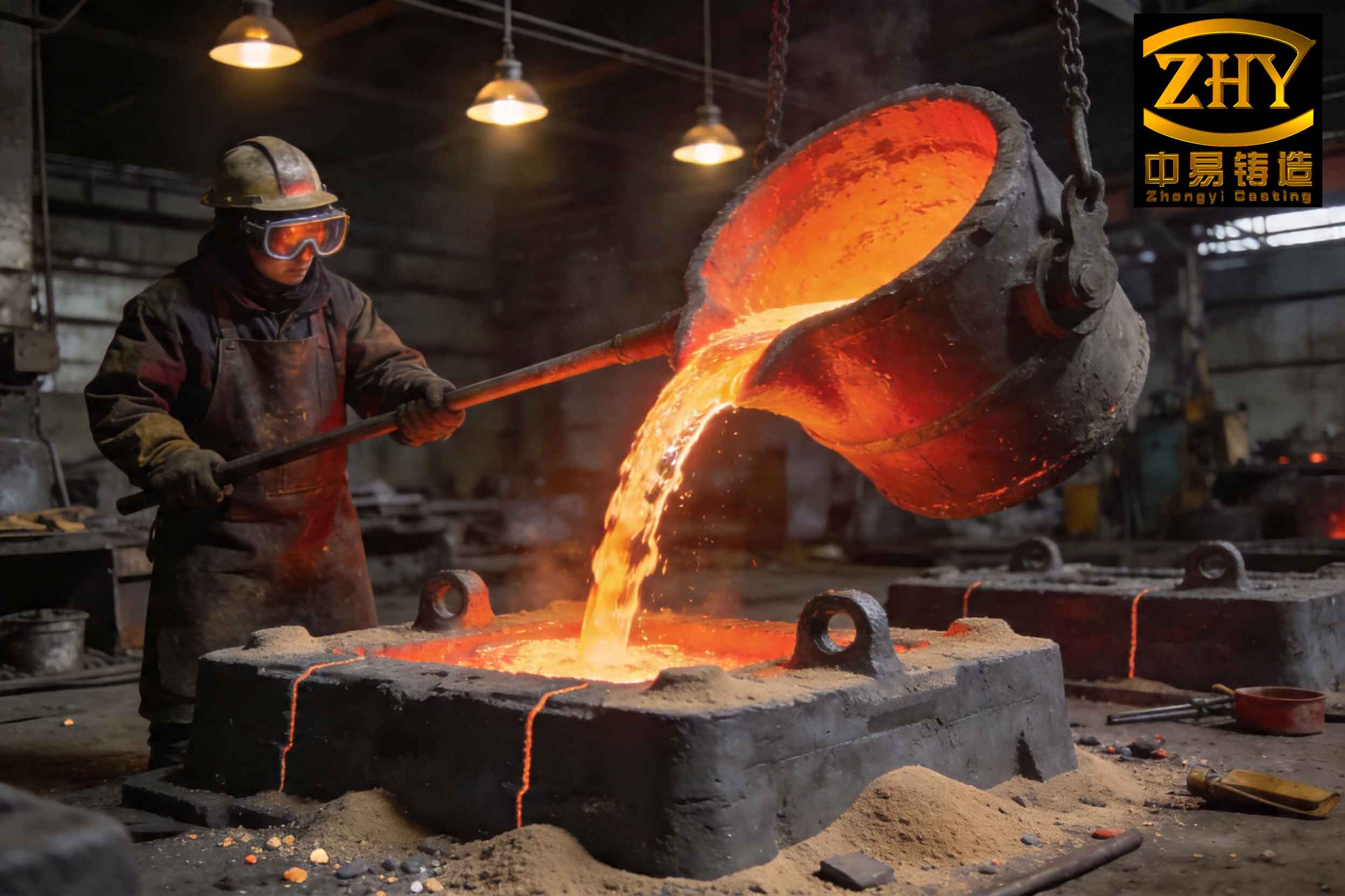
The detrimental effects of slag inclusion are multifaceted. They act as stress concentrators, drastically reducing fatigue strength and elongation. In pressure-containing components, they are a common source of leaks. The variability in their occurrence makes them a major contributor to scrap rates, driving up production costs. Therefore, a holistic approach targeting both melt treatment and casting system design is essential for mitigation.
A compelling case study involves the production of a large gas turbine component made from ductile iron grade QT400-18. The casting was substantial, with a diameter of 1910 mm, a height of 1219 mm, and a weight of 4500 kg. The initial manufacturing process utilized a furan resin no-bake mold, melting in a coreless induction furnace, and a semi-pressurized gating system. The chemical composition target was as follows:
| Element | Target Range (wt.%) |
|---|---|
| C | 3.5 – 3.7 |
| Si | 2.2 – 2.7 |
| Mn | 0.3 – 0.47 |
| P | ≤ 0.06 |
| S | ≤ 0.05 |
The original gating design featured a single downgate with an area Fsprue, a horizontal runner, and four ingates with a total area Fingate. The system was semi-pressurized, meaning the sprue area was the smallest, creating a pressurized flow. The ratio was ΣFsprue : ΣFrunner : ΣFingate = 1 : 2.99 : 0.77. Pouring temperature was maintained between 1350-1380°C.
This design led to catastrophic results. Severe slag inclusion defects were found on the upper surfaces of the flange and bearing housings. Out of an initial batch, the scrap rate reached 26.7%. Analysis pinpointed the cause: the high velocity of metal entry into the mold cavity. The theoretical ingate velocity can be approximated using the basic Bernoulli equation for a free-falling liquid:
$$ v = \sqrt{2gh} $$
Where \( v \) is velocity, \( g \) is gravity, and \( h \) is the effective metallostatic head. With a high head and a choked (pressurized) system, the metal entered at an estimated 0.91 m/s. This high-speed, turbulent flow caused severe agitation, air entrainment, and re-oxidation of magnesium, generating massive amounts of secondary slag within the mold cavity itself.
The solution required a fundamental redesign based on the “large orifice outflow” theory. The goal was to achieve calm, laminar filling by reducing entry velocity. This is accomplished by using an unpressurized, or open, gating system where the sprue is the smallest cross-section, and each subsequent element is larger. The recommended ratio for ductile iron is typically ΣFsprue : ΣFrunner : ΣFingate = 1 : (1.5-2) : 2.
The redesign process followed these calculated steps:
1. Pouring Time: An appropriate fill time was calculated based on casting weight and section thickness to avoid mistruns and excessive temperature loss.
$$ t_{pour} = f \left( \sqrt{G_{casting}} + \frac{1}{5} \sqrt[3]{\delta \cdot G_{casting}} \right) \times \frac{2}{3} $$
Where \( t_{pour} \) is pouring time (s), \( f \) is a resistance coefficient (0.8 for bottom gating), \( G_{casting} \) is casting mass (kg), and \( \delta \) is main wall thickness (mm). For a 4500 kg casting, the calculated pour time was 66 seconds.
2. Choke Area: The required sprue area to achieve this pour time was determined.
$$ A_{choke} = \frac{22.6 \times W}{\rho \times t_{pour} \times f_v \sqrt{H_p}} $$
Where \( W \) is total metal poured (6000 kg), \( \rho \) is density (6.9 kg/cm³ for iron), \( f_v \) is velocity coefficient (0.4 for bottom gate), and \( H_p \) is average metallostatic head (250 cm). The calculated choke area \( A_{choke} \) was 52 cm².
3. Gating System Design: A ceramic tube of Ø80 mm (area ~50.3 cm²) was selected for the sprue. Following open system principles, the runner was designed with a rectangular cross-section of 9 cm x 6 cm (area 54 cm²). To further distribute flow and reduce velocity, thirteen Ø35 mm ceramic tubes were used as ingates (total area ~125 cm²). The final gating ratio was:
$$ \Sigma F_{sprue} : \Sigma F_{runner} : \Sigma F_{ingate} = 1 : 2.15 : 2.49 $$
This is a fully open system.
4. Entry Velocity: The new ingate velocity was recalculated.
$$ V_{ingate} = \frac{10 \sqrt{H_p}}{n \times 22.6} $$
Where \( n \) is the ratio \( \Sigma F_{ingate} / \Sigma F_{sprue} \). The new velocity was 0.28 m/s, a reduction of nearly 70% from the original turbulent 0.91 m/s.
| Parameter | Original (Semi-Pressurized) Design | Improved (Open) Design |
|---|---|---|
| Gating Ratio (ΣFs:ΣFr:ΣFi) | 1 : 2.99 : 0.77 | 1 : 2.15 : 2.49 |
| Number of Ingates | 4 | 13 |
| Calculated Ingate Velocity (m/s) | ~0.91 | ~0.28 |
| Flow Character | Turbulent, Pressurized | Laminar, Unpressurized |
| Primary Defect Mechanism | Severe re-oxidation & secondary slag inclusion formation inside cavity. | Minimized turbulence, preventing slag generation during fill. |
The results were transformative. The first trial casting produced without any observable slag inclusion defect. In subsequent production of 34 castings, only one was scrapped for this reason, reducing the scrap rate from 26.7% to approximately 3%. While the open system required slightly more excess metal (150 kg per casting), the dramatic reduction in scrap yielded a net saving per casting, proving the technical and economic efficacy of the solution. This principle of designing for low-entry velocity via open gating systems has since been successfully applied to other castings prone to slag inclusion defects.
Beyond gating design, a comprehensive strategy to combat slag inclusion encompasses the entire production chain:
| Process Stage | Key Control Measures to Reduce Slag |
|---|---|
| Melting & Treatment | Maintain low sulfur levels pre-inoculation. Use clean, dense charge materials. Perform effective slag raking after Mg-treatment. Consider protective slag covers or tundish covers during transfer. |
| Pouring System Design | Employ open, unpressurized systems (ΣFs < ΣFr < ΣFi). Use ceramic filters in the runner. Design for bottom or horizontal filling with minimal flow distance. Calculate and minimize ingate velocity. |
| Mold & Pouring | Ensure dry, well-ventilated molds. Maintain a consistent, non-turbulent pour from the ladle to minimize surface agitation and oxide film entrainment. |
The fight against slag inclusion is a central theme in achieving high-quality ductile iron castings. It requires a deep understanding of both physical and chemical metallurgy—from the reactions in the cupola charge to the fluid dynamics of mold filling. The case of the gas turbine component powerfully illustrates that often the most effective remedy lies not in complex chemistry adjustments, but in the rigorous application of fluid flow principles during casting design. By integrating controlled melting practices, optimized treatment procedures, and scientifically designed gating systems that prioritize quiescent filling, foundries can significantly suppress the formation of both primary and secondary slag inclusion, thereby enhancing mechanical properties, improving yield, and delivering more reliable cast components.