
In my extensive experience with aluminum casting production, particularly for critical aerospace components, I have encountered persistent challenges related to slag inclusion defects. This article delves into the investigation of slag inclusion problems in large skeleton-type aluminum castings, drawing from practical case studies and theoretical analyses. The focus is on understanding the root causes and developing effective浇注系统 designs to minimize slag inclusion, which is a prevalent defect that compromises structural integrity and performance. I will present detailed insights, supported by formulas and tables, to elucidate the mechanisms and solutions.
The skeleton casting under discussion is a high-stress component used in aviation applications, characterized by an I-beam structure with complex geometries. Key dimensions include a maximum envelope of 350 mm × 428 mm × 682 mm, with wall thicknesses varying from 12 mm to 50 mm. The material is ZL104 alloy, and the casting weight is approximately 40 kg. Due to severe operational vibrations, quality standards are stringent, requiring 100% X-ray inspection per HB963-82-II class specifications. Historically, during initial trials in 1989, severe slag inclusion defects were observed, primarily in the lower翼板 and腹板 regions, prompting a thorough re-evaluation of铸造工艺.
Production conditions involved melting ZL104 alloy in a 500 kg resistance furnace, using hexachloroethane (CCl3·CCl3) as a refining agent and dual-color modification blocks at 1% of the melt weight. Conventional melting practices were followed, with a浇注温度 range of 710°C to 730°C. Molding utilized oil-sand cores for the main cavity, with clay-based molding sand of粒度70/140, and manual造型 techniques. These conditions, while standard, contributed to the propensity for slag inclusion formation if the浇注系统 was not optimized.
The core of the problem lies in the浇注系统 design. Initially, two浇注系统 schemes were employed: a direct-drop type and a stepped-buffer type, both incorporating chink浇道 as the primary delivery method. These systems introduced alloy liquid from the sides of the腹板, but analysis revealed that slag inclusion occurred systematically in the lower翼板和腹板 areas. This pattern indicated a direct correlation with浇注系统 dynamics. To quantify the impact, I calculated the initial冲击 velocity of the alloy liquid using the formula for free fall: $$ v = \sqrt{2gh} $$ where \( v \) is the velocity, \( g \) is the acceleration due to gravity (9.8 m/s²), and \( h \) is the drop height. For a drop of 900 mm (0.9 m), the velocity is: $$ v = \sqrt{2 \times 9.8 \times 0.9} \approx 4.2 \, \text{m/s} = 4200 \, \text{mm/s} $$. This high velocity caused intense splashing and涡流 in the斜浇口 regions, leading to significant secondary oxidation and slag inclusion formation. The stepped-buffer scheme reduced the direct drop to 600 mm, lowering the velocity to approximately 3.4 m/s, which mitigated but did not eliminate slag inclusion.
To better illustrate the differences between the original schemes, I have compiled a table summarizing their parameters and slag inclusion outcomes:
| 浇注系统 Scheme | Drop Height (mm) | Calculated Velocity (m/s) | Slag Inclusion Severity (Lower翼板) | Slag Inclusion Severity (腹板) | Key Issues |
|---|---|---|---|---|---|
| Direct-Drop (Scheme a) | 900 | 4.2 | Severe | Severe | High冲击, splashing,涡流 in斜浇口 |
| Stepped-Buffer (Scheme b) | 600 | 3.4 | Moderate | Reduced | Partial缓冲, but斜浇口 still causes涡流 |
From this analysis, it became clear that the浇注系统 connected to the chink浇道 was fundamentally flawed, as it failed to provide adequate缓冲 and slag removal. The slag inclusion defects were exacerbated by the large planar areas of the腹板, where thin walls (12 mm) allowed rapid solidification, trapping slag inclusions before they could float to the surface. The lower翼板, with its curved structure and ribs, also hindered slag exclusion. Thus, the primary cause of slag inclusion was identified as improper浇注系统 design leading to turbulent flow and oxidation.
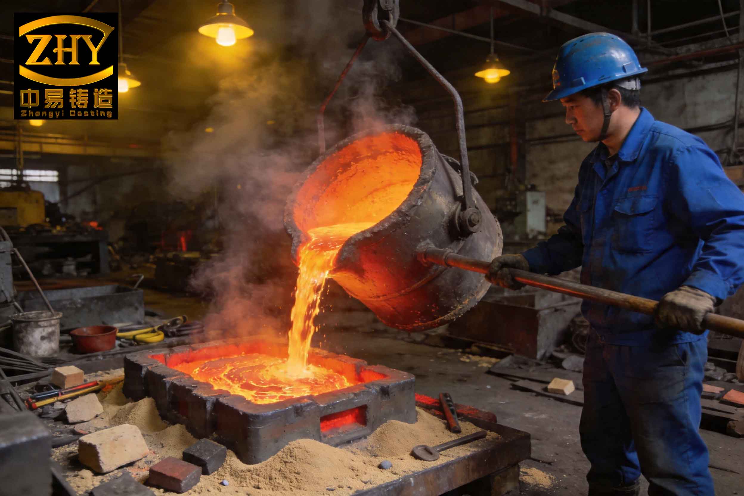
To address these issues, I proposed and implemented a novel浇注系统: a复合式缝隙浇注系统 incorporating过滤网. This design aimed to enhance缓冲 and slag过滤 capabilities. Key modifications included relocating the横浇道 to a higher position at 650 mm (at the parting plane), connecting it to a serpentine浇口 (snake-like channel) with a diameter of 25 mm, which then fed into a vertical立筒.过滤网 were strategically placed in both the横浇道 and the立筒 to capture slag inclusions at multiple stages. The直浇道 was changed to two conical rods of 16 mm diameter to reduce氧化, and the横浇道 cross-section was set at 30/40 mm × 50 mm to improve slag浮选. The area ratios of the浇注系统 components were calculated as follows: $$ F_{\text{直}} : F_{\text{横}} : F_{\text{蛇}} = 4 : 35 : 10 \approx 1 : 9 : 2.5 $$ where \( F \) represents the cross-sectional area. This ratio ensured a balanced flow with minimized turbulence.
The effectiveness of this new浇注系统 can be understood through fluid dynamics principles. The缓冲 effect of the serpentine浇口 reduces the kinetic energy of the alloy liquid, decreasing the雷诺数 and promoting laminar flow. The雷诺数 is given by: $$ Re = \frac{\rho v D}{\mu} $$ where \( \rho \) is density, \( v \) is velocity, \( D \) is hydraulic diameter, and \( \mu \) is dynamic viscosity. Lower \( Re \) values reduce turbulence, thereby minimizing slag inclusion formation. Additionally, the过滤网 act as barriers to slag particles, with their efficiency depending on pore size and flow rate. I derived a simple model for slag capture: $$ \eta = 1 – e^{-k \cdot A \cdot t} $$ where \( \eta \) is the capture efficiency, \( k \) is a constant related to过滤网 properties, \( A \) is the surface area, and \( t \) is the exposure time. This model highlights how multiple过滤网 enhance overall slag removal.
To compare the old and new浇注系统 designs, I present a comprehensive table:
| Aspect | Original浇注系统 (Scheme a/b) | New复合式浇注系统 | Improvement |
|---|---|---|---|
| Drop Height to立筒 | 900 mm / 600 mm | 650 mm (with serpentine缓冲) | Reduced冲击 velocity by ~25% |
| 缓冲 Mechanisms | Minimal (仅横浇道 in Scheme b) | 横浇道 + serpentine浇口 | Enhanced flow stabilization |
| Slag过滤 | Limited (仅立筒 in some cases) | Dual过滤网 (横浇道 and立筒) | Multi-stage slag inclusion capture |
| Flow Velocity at Entry | High (4.2 m/s for Scheme a) | Controlled (< 2 m/s estimated) | Minimized splashing and涡流 |
| 浇道 Area Ratio | Not optimized | 1 : 9 : 2.5 (直:横:蛇) | Balanced pressure distribution |
| Observed Slag Inclusion Rate | 100% in lower regions | Negligible per X-ray standards | Near-elimination of defects |
Implementation of this new浇注系统 resulted in the production of 24 castings, all of which passed X-ray inspection符合 HB963-82-II class requirements, effectively resolving the slag inclusion problem. The success underscores the importance of integrating缓冲 elements and过滤网 in浇注系统 design for large aluminum castings. In my discussion, I generalize these findings to similar skeleton-type castings with I-beam geometries. For instance, tall aluminum castings can benefit from multi-layer横浇道 to further enhance缓冲, and the use of过滤网 should be considered mandatory for high-quality production. I also caution against the use of斜浇口 in large castings due to their tendency to induce涡流 and slag inclusion.
To further quantify the benefits, I analyzed the energy dissipation in the serpentine浇口. The pressure loss due to friction can be estimated using the Darcy-Weisbach equation: $$ \Delta P = f \cdot \frac{L}{D} \cdot \frac{\rho v^2}{2} $$ where \( \Delta P \) is the pressure drop, \( f \) is the friction factor, \( L \) is the length of the浇道, and \( D \) is the diameter. For a serpentine浇口 with multiple bends, additional losses occur, but overall, this dissipates kinetic energy, reducing the potential for slag inclusion formation. Moreover, the inclusion of过滤网 adds a pressure drop that further slows the flow, modeled as: $$ \Delta P_{\text{filter}} = \frac{\mu Q}{k A} $$ where \( Q \) is the flow rate, \( \mu \) is viscosity, \( k \) is permeability, and \( A \) is the过滤网 area. This combined approach ensures a calm fill into the mold cavity.
In practice, I have observed that slag inclusion defects often stem from multiple sources, including熔炼 practices, but the浇注系统 plays a pivotal role. For ZL104 alloy, which is prone to oxidation, maintaining a平静的 flow is critical. The table below summarizes key factors influencing slag inclusion in aluminum castings:
| Factor | Contribution to Slag Inclusion | Mitigation Strategy |
|---|---|---|
| High浇注 Velocity | Increases氧化 and entrains slag | Use缓冲浇道 (e.g., serpentine) |
| Turbulent Flow | Promotes slag suspension and inclusion | Optimize浇道 ratios and designs |
| Inadequate Slag Removal | Allows slag to enter cavity | Incorporate multiple过滤网 |
| Large Drop Heights | Causes冲击 and splashing | Implement阶梯浇注 systems |
| Rapid Solidification in Thin Walls | Traps slag before flotation | Adjust浇注温度 and浇道 placement |
From this experience, I conclude that the root cause of severe slag inclusion in skeleton castings was the不合理浇注系统 connected to the chink浇道, which generated excessive turbulence and secondary oxidation. The proposed复合式缝隙浇注系统 with过滤网 proved highly effective, as it combined缓冲 through serpentine elements and dual-stage slag filtration. This approach is applicable to a wide range of large aluminum castings, especially those with complex geometries and high quality demands. Future work could involve computational fluid dynamics (CFD) simulations to further optimize浇道 designs and predict slag inclusion risks. For now, I emphasize that careful浇注系统 engineering, backed by empirical data and theoretical models, is essential for minimizing slag inclusion defects and ensuring reliable casting performance in critical applications.
In summary, this investigation highlights the critical interplay between浇注系统 dynamics and slag inclusion formation. By adopting a复合式浇注系统 with integrated缓冲 and过滤网, I achieved significant reductions in slag inclusion, demonstrating that proactive design modifications can overcome persistent casting defects. The lessons learned here are broadly applicable, reinforcing the importance of tailored solutions for specific casting challenges. As I continue to refine these techniques, I aim to develop standardized guidelines for浇注系统 design that prioritize slag inclusion prevention, ultimately enhancing the quality and durability of aluminum castings across industries.