
In my extensive career specializing in the production of massive castings, particularly rolling mill housings, I have encountered and addressed a vast array of defects. These components, often weighing hundreds of tons, represent the pinnacle of casting challenges. Their sheer size amplifies every minor process deviation, turning potential flaws into critical failures. Through firsthand experience, I have developed a systematic approach to understanding, preventing, and remedying these issues. This article distills that knowledge, focusing on the most prevalent defects: cracks, sand-related issues like burning and inclusions, shrinkage porosity, and coarse grain structure. A recurring adversary in this field is the problem of slag inclusions, which we will explore in significant depth. My goal is to provide a comprehensive, practical guide that leverages both empirical wisdom and fundamental metallurgical principles.
The journey of a casting from liquid metal to a robust structural component is fraught with potential pitfalls. For a mill housing, the stakes are exceptionally high due to its critical function and monumental cost. Defects not only compromise mechanical integrity but can lead to catastrophic failures in service, resulting in immense financial and operational losses. Therefore, a proactive, science-based approach to defect prevention is not merely beneficial—it is imperative. In the following sections, I will analyze each major defect category, propose detailed preventive strategies supported by data and calculations, and outline effective post-discovery remediation techniques.
1. The Perennial Challenge: Cracks and Fissures
Cracking is perhaps the most insidious defect, often lurking beneath the surface and revealing itself during machining or under load. Based on my observations, cracks predominantly initiate in high-stress concentration zones: beneath large feeders (risers), at sharp re-entrant angles of substantial bosses, around window openings, and near press screw holes. The fundamental cause is always an imbalance: when the internal stresses—thermal, transformational, or mechanical—exceed the localized strength of the material at a given point in the solidification and cooling process.
The underlying mechanism can be described by a simplified thermo-elastic stress relationship:
$$\sigma_{thermal} = E \cdot \alpha \cdot \Delta T$$
Where $\sigma_{thermal}$ is the induced thermal stress, $E$ is Young’s modulus, $\alpha$ is the coefficient of thermal expansion, and $\Delta T$ is the temperature gradient within the casting. In heavy sections, $\Delta T$ can be immense, leading to proportionally high stresses.
Prevention hinges on managing these stresses and enhancing local material strength. Key strategies I employ include:
- Metallurgical Control: Maintaining low levels of harmful elements like sulfur and phosphorus, which promote hot tearing. The carbon content is strategically controlled, often at the lower specification limit for the initial pour to improve weldability and toughness.
- Geometric Optimization: Generously increasing fillet radii at junctions. For example, a boss connection requires a radius no less than a calculated minimum based on section thickness difference. I often use the following rule-of-thumb:
$$R_{min} = 0.3 \times (T_{boss} + T_{wall})$$
where $T$ represents thickness. - Auxiliary Chills and Padding: Strategic use of external chills to control solidification sequence and padding (non-forming geometry) to create more uniform cooling.
- Heat Treatment: A full normalizing and tempering cycle is non-negotiable. It refines the microstructure, relieves residual stresses, and homogenizes mechanical properties, dramatically increasing fracture resistance.
The table below summarizes common crack locations and targeted countermeasures:
| Critical Location | Root Cause | Primary Preventive Measures |
|---|---|---|
| Under Feeders (Risers) | Chemical segregation, coarse grain, micro-shrinkage weakening the matrix. | Optimize feeder neck design for progressive freezing; use exothermic/insulating toppings. |
| Boss-Wall Junctions | Thermal contraction constraint leading to stress concentration. | Maximize fillet radius; apply arcuate washburn cores or cooling fins; place anti-cracking grids. |
| Window Openings | Massive contraction resistance from the core, leading to tensile stress. | Increase corner radii; incorporate multiple compliant layers (cushioning materials) in the core; omit restrictive binders. |
| Press Screw Holes | Extreme core rigidity causing high stress during cooling and shakeout. | Design core with reinforced steel skeleton and internal compliant layers; consider casting solid and drilling later. |
2. Sand Adhesion, Burn-On, and the Persistent Menace of Slag Inclusions
Defects related to the mold-metal interface and entrapped foreign materials are predominantly found in the upper sections of the cope. They stem from a breakdown in the integrity of the molding system or the purity of the molten metal. Among these, slag inclusions are a particularly frequent and damaging issue, often necessitating costly repair. Slag inclusions are non-metallic ceramic phases trapped within the metal matrix, acting as stress raisers and crack initiation sites.
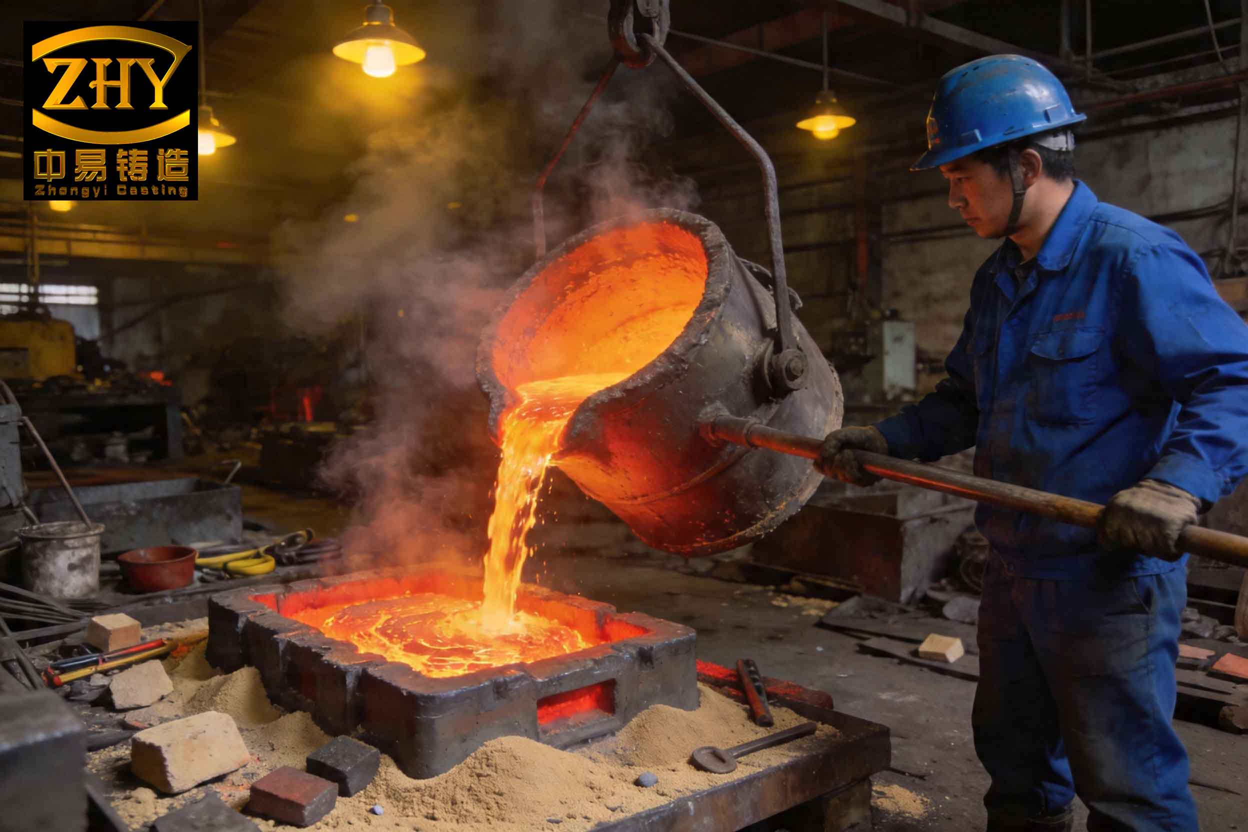
The genesis of slag inclusions and related defects is multifactorial:
- Mold Material Failure: Inadequate sand strength or refractoriness leads to surface erosion. The sand grains are then encapsulated by the metal, causing burn-on or mechanical penetration. If chunks dislodge, they become sand inclusions.
- Mold Drying Issues: Uneven or excessive drying causes sand layers to separate, creating ready-made failure planes.
- Metallurgical Sources of Slag: This is the primary origin of true slag inclusions. They form from oxidation products (e.g., $FeO$, $MnO$, $SiO_2$), refractory linings, or deoxidation products (e.g., $Al_2O_3$ clusters) that are not properly floated out before or during pouring. The kinetic energy of the stream can emulsify slag, making separation difficult. The Stokes’ law governs the flotation velocity:
$$v = \frac{2}{9} \cdot \frac{(\rho_m – \rho_s) \cdot g \cdot r^2}{\eta}$$
where $v$ is rising velocity, $\rho_m$ and $\rho_s$ are densities of metal and slag, $g$ is gravity, $r$ is inclusion radius, and $\eta$ is metal viscosity. Small-radius inclusions ($r$) have very low $v$, making them likely to be trapped.
My preventive regimen is rigorous and multi-pronged, with special emphasis on eliminating slag inclusions:
| Defect Type | Causal Factor | Preventive Action Plan |
|---|---|---|
| Sand Burn-On/Penetration | Low sand refractoriness, high pouring temperature. | Use chromite or zircon sand for critical surfaces; apply refractory washes (e.g., magnesia-based); control pouring temperature to lower limit. |
| Sand Inclusions | Low mold/core strength, loose sand. | Implement strict sand property control (AFS GFN, strength, moisture); increase mold nail density; seal surfaces with iron plates. |
| Slag Inclusions | Poor metal cleanliness, turbulent pouring, slag entrainment. |
|
Vigilance against slag inclusions must be maintained throughout the entire process, from furnace tapping to mold filling. Any breach in protocol can introduce these detrimental particles.
3. Shrinkage Porosity and Cavities: The Quest for Soundness
Given the enormous volume of steel in a mill housing, the total liquid contraction and solidification shrinkage are substantial. This volumetric deficit, if not continuously fed with liquid metal, results in macro-porosity (shrinkage cavities) or micro-porosity (shrinkage scattered, or dispersed shrinkage). These defects severely reduce load-bearing cross-sections and fatigue life.
The principle is governed by the law of mass conservation and solidification kinetics. The critical parameter is the Modulus ($M$), defined as the volume ($V$) to cooling surface area ($A$) ratio: $$M = \frac{V}{A}$$. Sections with higher $M$ solidify slower and require feeding for a longer duration. The famous Chvorinov’s rule states solidification time $t_s$ is proportional to the square of the modulus: $$t_s = k \cdot M^2$$ where $k$ is the mold constant.
My approach to preventing shrinkage defects is a calculated sequence of steps:
- Modulus Calculation & Feeder Design: I meticulously calculate the modulus for every section of the housing. Feeders are designed to have a higher modulus than the casting section they feed (typically $M_{feeder} > 1.2 \times M_{casting}$) to ensure they remain liquid longest. The required feeder volume $V_f$ is estimated as:
$$V_f = \frac{ \beta \cdot V_c }{ \eta – \beta }$$
where $V_c$ is the casting volume to be fed, $\beta$ is the total volumetric shrinkage from liquid to room temperature (approx. 6-7% for carbon steel), and $\eta$ is the feeder efficiency (typically 0.1-0.3 for open top feeders). - Chill Application: External chills are used to create directional solidification toward the feeders. Their size and spacing are critical. The chill’s ability to extract heat is a function of its density, specific heat, and contact area. An array of chills can be modeled to ensure a positive thermal gradient.
- Pouring & Feeding Protocol: The gating system is designed to establish thermal gradients favorable to feeding. After the main pour, I mandate a strict schedule for “topping up” the feeders with hot metal to compensate for liquid shrinkage before the feeder neck seals. The use of exothermic and insulating compounds on feeder tops is standard to prolong their liquid state.
A summary of the shrinkage control strategy is presented below:
| Defect Manifestation | Primary Cause | Corrective & Preventive Strategy |
|---|---|---|
| Shrinkage Cavity under Feeder | Premature freezing of feeder neck, insufficient feeder volume. | Increase feeder neck cross-section; use neck heating or exothermic sleeves; increase feeder size per modulus calculation. |
| Centerline or Inter-feeder Shrinkage | Inadequate thermal gradient between two adjacent hot spots. | Place intervening chills; use padding to create a feeding path; adjust feeder placement or add blind feeders. |
4. Coarse Grain Structure: Refining the Metallic Matrix
In heavy-section castings, prolonged solidification times allow for extensive grain growth, leading to a coarse austenitic grain structure that transforms into correspondingly coarse ferrite-pearlite or bainitic structures. This coarseness detrimentally impacts toughness, yield strength, and fatigue resistance. In ultrasonic testing, it manifests as high noise and loss of back echo, complicating flaw detection.
The grain size ($d$) after solidification is influenced by the undercooling ($\Delta T$) and nucleation rate ($N$), following relationships akin to:
$$d \propto (G \cdot v)^{-1/n}$$
where $G$ is the temperature gradient and $v$ is the growth velocity. For diffusional growth, $n$ is often around 2. Slow cooling (low $G$, low $v$) results in large $d$.
My strategies to combat coarse grains involve both metallurgical and thermal interventions:
- Inoculation/Grain Refinement: Introducing potent heterogeneous nucleation sites into the melt. Additions of titanium (forming TiN, TiC) or aluminum (forming AlN) are highly effective. These particles provide substrates for austenite grains to nucleate upon, dramatically increasing the grain count. The effect can be modeled by the free growth model, where a critical undercooling is needed to activate a particle of a given size.
- Optimized Heat Treatment: A carefully designed normalizing cycle is crucial. The key is to ensure the entire casting cross-section reaches and holds at the austenitizing temperature long enough for complete recrystallization but not so long as to promote grain growth. For very heavy sections, I specify stepped heating and extended holding times to minimize thermal gradients within the piece itself. The cooling rate during normalizing must be sufficiently fast to suppress excessive grain growth. This often requires forced air or mist cooling in specific zones of the furnace.
- Process Control: Minimizing overall solidification time through optimal molding materials and controlled pouring temperature helps, but its effect is limited in such massive sections compared to inoculation and heat treatment.
The relationship between properties and grain size is often described by the Hall-Petch equation for strength:
$$\sigma_y = \sigma_0 + k_y \cdot d^{-1/2}$$
where $\sigma_y$ is yield strength, $\sigma_0$ and $k_y$ are material constants. This clearly shows the benefit of a finer grain size ($d$).
5. Methodology for Defect Remediation: The Art of Repair
Despite all precautions, defects sometimes occur. A systematic, disciplined approach to repair is essential to restore integrity without introducing new problems. The cardinal rule is: Never rush a repair.
My standard operating procedure for defect removal and repair is as follows:
- Defect Mapping & Analysis: Fully delineate the defect using NDT methods (UT, MT, PT). Understand its geometry, depth, and proximity to critical features.
- Mechanical Removal Preferred: Use milling, grinding, or arc-air gouging with subsequent grinding to remove defective material. This minimizes the heat-affected zone (HAZ).
- Thermal Cutting Protocols: When thermal methods (oxy-fuel, plasma) are necessary, mandatory pre-heating of the area is conducted. The pre-heat temperature ($T_{pre}$) is determined based on carbon equivalent (CE):
$$CE = C + \frac{Mn}{6} + \frac{Cr+Mo+V}{5} + \frac{Ni+Cu}{15}$$
For CE > 0.4, $T_{pre}$ > 150°C. The heating must be uniform to minimize thermal stresses. - Crack Arrest: For cracks, the first step is always to drill stop-holes at both termini to blunt the crack tip and relieve the stress concentration, following the principles of fracture mechanics where stress intensity factor $K_I$ is reduced.
- Verification & Preparation: After removal, the cavity is thoroughly cleaned and inspected again with PT/MT to ensure all defective material and micro-cracks are gone. The cavity is shaped with smooth contours and suitable bevels for welding.
- Welding Procedure: Use a qualified welding procedure specification (WPS) with low-hydrogen electrodes. Maintain interpass temperature control. For deep repairs, use temper bead techniques or in-process stress relief.
- Post-Weld Heat Treatment (PWHT): Local or full PWHT is often necessary to temper the HAZ and relieve residual stresses from the repair weld.
- Final Inspection: The repaired area undergoes full NDT (UT, MT, PT) and often hardness testing to ensure quality.
- For “No Back Echo” Zones: Areas showing ultrasonic attenuation due to coarse grains are subjected to a second normalizing heat treatment cycle, precisely controlled to promote grain refinement without causing distortion.
The entire process is documented in a repair plan that includes cause analysis for the original defect to prevent recurrence. This closed-loop feedback is vital for continuous process improvement.
6. Holistic Process Integration and Concluding Thoughts
Preventing defects in heavy castings like mill housings is not about a single silver bullet. It is the integration of countless controlled steps—from sand preparation and core making, through metallurgy and pouring, to heat treatment and finishing. Each step presents an opportunity to introduce a flaw, but also a chance to enforce quality. A culture of rigorous discipline, underpinned by scientific understanding, is the true foundation of success.
The fight against slag inclusions, cracks, shrinkage, and coarse grains is won in the details: the calibration of a thermocouple, the sieve analysis of sand, the calculation of a feeder modulus, the precise timing of a deoxidation addition. Tables, calculations, and formulas are not mere academic exercises; they are the blueprints for sound metal. By sharing this detailed, first-person perspective, I hope to underscore that while the castings we produce are monumental in size, the margin for error is often minuscule. Mastery lies in controlling the continuum between these two extremes, ensuring that every ton of metal poured transforms into a component of unwavering reliability and strength.
In closing, remember that the most effective “treatment” for a casting defect is its prevention. Investment in robust process design, material control, and personnel training yields far greater returns than the most skillful repair. Let this guide serve as a testament to the intricate art and demanding science of producing flawless heavy castings.