
In my extensive experience within the foundry industry, the formation of slag inclusions remains one of the most persistent and costly defects affecting cast iron components. These non-metallic inclusions, primarily composed of oxides, sulfides, and silicates, are introduced into the mold cavity alongside the molten metal. Their presence severely compromises the mechanical properties, pressure tightness, and machinability of the final casting, often leading to outright rejection, especially in high-integrity applications like machine tool hydraulics. The battle against slag inclusions is fought on multiple fronts: melting, pouring, and molding. A holistic strategy, encompassing rigorous process control at every stage and intelligent gating system design, is essential for effective mitigation.
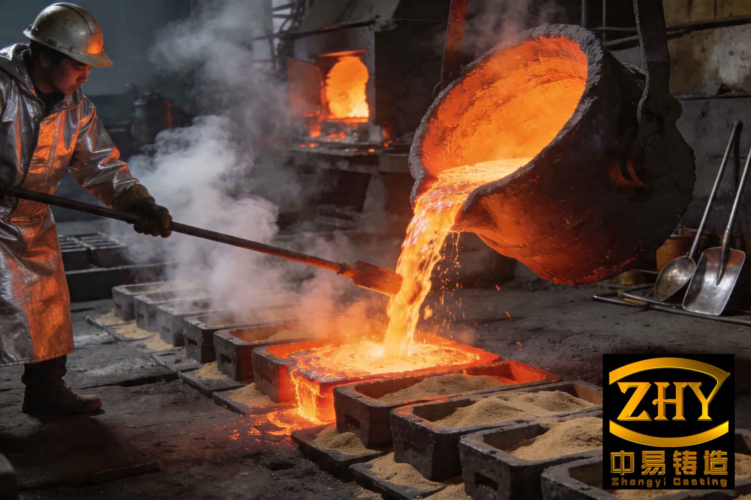
The genesis of slag inclusions lies in the melting process. In a cupola furnace, slag is formed from the ash of coke, ingested sand, and eroded refractory lining. This initial slag is often viscous and difficult to remove. The key intervention is the addition of fluxing agents, typically limestone (CaCO3), which decomposes to lime (CaO). The lime reacts with acidic oxides in the slag (like SiO2, Al2O3) to form lower-melting-point, fluid calcium silicates and aluminates.
$$ \text{CaCO}_3 \xrightarrow{\Delta} \text{CaO} + \text{CO}_2 \uparrow $$
$$ \text{CaO} + \text{SiO}_2 \rightarrow \text{CaSiO}_3 $$
$$ \text{CaO} + \text{Al}_2\text{O}_3 \rightarrow \text{CaAl}_2\text{O}_4 $$
This fluid slag can then separate from the iron in the well or forehearth due to density differences. The efficiency of this separation is governed by Stokes’ law, which describes the upward velocity of a slag particle:
$$ v_s = \frac{2(\rho_m – \rho_s) g r^2}{9 \eta} $$
where:
$v_s$ = settling (rising) velocity of the slag particle,
$\rho_m$ = density of molten metal,
$\rho_s$ = density of slag,
$g$ = acceleration due to gravity,
$r$ = radius of the slag particle,
$\eta$ = dynamic viscosity of the molten metal.
This equation highlights critical control parameters: slag particle size ($r$) and metal temperature (which greatly influences $\eta$). Higher superheat reduces metal viscosity, allowing smaller slag particles to float out more quickly. Insufficient flux or low temperature results in viscous slag that is prone to being trapped in the metal stream, directly increasing the risk of slag inclusions. Regular and timely slag tapping from the forehearth is a non-negotiable operational discipline.
| Parameter | Target / Optimal Practice | Effect on Slag Formation & Removal |
|---|---|---|
| Flux Addition (Limestone) | 1.5 – 3.0% of metal charge | Lowers slag melting point and viscosity, promotes fluidity. |
| Metal Superheat Temperature | ≥ 150°C above liquidus | Lowers metal viscosity ($\eta$), enhances slag particle buoyancy ($v_s$). |
| Slag Basicity (CaO/SiO2) | 1.0 – 1.3 | Ensures slag is fluid and reactive; values outside range lead to viscous slag. |
| Forehearth Slag Tap Frequency | Regular, based on melt rate | Prevents accumulation and re-entrainment of slag into metal stream. |
Despite best efforts in the melting department, some slag is invariably transferred to the ladle. This is where the second line of defense—pouring operations—takes over. The primary task is “slag skimming” or “raking.” Merely using a bar is inefficient. The proven method involves applying a drossing agent or slag coagulant to the surface of the metal in the ladle. These agents, often expanded perlite or proprietary compounds, create a semi-molten, viscous layer that encapsulates the dispersed slag particles, agglomerating them into a manageable “cake” that can be easily removed.
The effectiveness of a drossing agent can be evaluated by its ability to reduce the interfacial tension between the metal and the slag, promoting coalescence. The work of adhesion, $W_{ad}$, between the slag phase and the drossing agent should be high:
$$ W_{ad} = \gamma_{mg} + \gamma_{sg} – \gamma_{ms} $$
where $\gamma_{mg}$, $\gamma_{sg}$, and $\gamma_{ms}$ are the interfacial tensions at the metal-gas, slag-gas, and metal-slag boundaries, respectively. A good agent modifies these tensions to favor slag agglomeration. During pouring, a dedicated pourer must use a slag stopper or skim bar to actively block the ladle lip, preventing the final layer of metal, which contains the remaining slag, from entering the sprue. Furthermore, maintaining a continuous, non-turbulent pour is critical. A broken stream aspirates air and disrupts the slag-trapping mechanisms within the gating system, directly funneling slag inclusions into the casting cavity.
| Agent Type | Primary Composition | Mechanism of Action | Advantages | Disadvantages |
|---|---|---|---|---|
| Expanded Perlite | Amorphous volcanic glass (SiO2, Al2O3, K2O) | Insulates, forms a viscous physical barrier, entraps slag. | Excellent insulation, effective agglomeration, low cost. | Can be dusty; less effective on very fluid slags. |
| Proprietary Coagulants | Blends of oxides, fluorides, carbonates | Chemically reacts with slag to increase viscosity and coalescence. | Highly effective agglomeration, works on a wide slag range. | Higher cost, potential for fumes. |
| Charcoal / Rice Hull Ash | Carbon, SiO2 | Creates a reducing atmosphere, forms a insulating layer. | Good insulation, mild reducing effect. | Poor slag coalescence ability, limited protection. |
| Dry Sand | SiO2 | Forms a crust on metal surface. | Readily available, very low cost. | Minimal slag agglomeration, can contaminate metal with sand. |
The final and most sophisticated defense against slag inclusions is engineered within the mold itself: the gating and feeding system. Its design principles are fundamentally aimed at controlling fluid dynamics to promote slag separation. The sprue basin or pouring cup must be designed to minimize vortex formation. A vortex acts as a funnel, drawing surface slag directly into the sprue. A properly designed basin with a dam and well helps ensure that only metal from beneath the surface enters the sprue.
The sprue should be tapered to prevent aspiration. The key arena for slag removal is the runner. Its primary function is not just to distribute metal, but to act as a “slag trap.” To achieve this, the runner cross-section is designed to be wide and shallow (a “high trapezoid”), which maintains a high horizontal flow velocity while providing a large upper surface area for slag to float to. The velocity profile in a runner is parabolic; slag particles near the top experience lower downward drag forces and can separate. The first ingate should be placed at a minimum distance from the sprue well, known as the “slag trapping length” $L_{min}$.
$$ L_{min} = k \cdot v_h \cdot t_s $$
where:
$v_h$ is the horizontal flow velocity in the runner,
$t_s$ is the time required for a critical slag particle size to float to the top,
$k$ is a safety factor (typically 1.5-2.0).
The time $t_s$ can be approximated from the modified Stokes’ law, considering the runner height $H$: $t_s \approx H / v_s$. Ingates are attached at the bottom of the runner, drawing clean metal from the lower stratum, while the slag-rich upper layer continues past them into extended runner channels or blind risers.
For castings where even trace slag inclusions are unacceptable, specialized gating systems are employed. These systems create deliberate flow disturbances or chambers to enhance slag separation beyond what a standard runner can achieve.
- Whirl Gate / Centrifugal Separator: This is arguably the most effective passive slag removal device. The metal is introduced tangentially into a cylindrical chamber. The resulting centrifugal force throws denser metal to the periphery, while the less dense slag is forced toward the center, where it floats up and is trapped. The clean metal exits from a radial outlet at the chamber’s bottom. The separation efficiency depends on the tangential velocity $v_t$ and the chamber radius $R_c$. The centrifugal acceleration $a_c$ is given by:
$$ a_c = \frac{v_t^2}{R_c} $$
This acceleration can be many times greater than gravity ($g$), dramatically increasing the effective settling force on slag particles and making this system exceptionally efficient at removing even fine slag inclusions.
- Strainer Cores & Choke Systems: A physical barrier like a ceramic foam filter or a sand core with small holes acts as a mechanical sieve, trapping slag. A choke, or a constriction in the early part of the gating system (often at the sprue base), increases metal velocity locally, creating pressure drops that can help hold back slag. The design must balance slag removal with the risk of eroding the choke or causing excessive turbulence.
- Runner Step/Expansion & Skim Gates: A sudden expansion in the runner area reduces flow velocity, allowing more time for slag to float ($t_s$ increases). A “skim gate” is a vertical offtake from the top of the runner designed specifically to catch and hold the initial slag-laden metal, preventing it from proceeding further.
| System Type | Mechanism of Action | Separation Force / Principle | Best For | Considerations |
|---|---|---|---|---|
| Whirl Gate (Centrifugal) | Tangential inlet creates vortex. | Centrifugal force ($a_c = v_t^2/R_c$). | High-integrity, medium to large castings. | Excellent efficiency; adds complexity; requires careful sizing. |
| Ceramic Foam Filter | Mechanical interception. | Sieving; depth filtration. | All casting sizes, esp. non-ferrous and steel. | Very effective but adds cost; can cause chill if not preheated. |
| Choke / Restrictive System | Creates pressure drop and high initial velocity. | Bernoulli’s principle; slag is “held back” at pressure transition. | Small to medium iron castings. | Can be erosive; must ensure full gating area ratios are correct. |
| Skim Gate / Blind Riser on Runner | Provides a calm, top-fed reservoir for slag to accumulate. | Buoyancy (gravity) and flow diversion. | All castings, as a secondary trap. | Simple and reliable; consumes some metal. |
In summary, the eradication of slag inclusions is not a matter of a single silver bullet but a relentless, multi-stage campaign. It begins with disciplined melting practices to minimize slag generation and promote its separation, continues with meticulous pouring procedures to remove entrained slag, and is cemented by the intelligent design of the mold’s gating system to act as a final, highly effective filter. Each stage has quantifiable parameters—temperature, viscosity, particle size, flow velocity, runner geometry, centrifugal acceleration—that can be modeled, calculated, and optimized. By mastering the interplay of these factors, foundries can significantly reduce the incidence of slag inclusions, thereby enhancing casting quality, yield, and overall operational efficiency. The fight against slag is a fundamental test of foundry process control, and victory is achieved through a combination of sound science and unwavering procedural discipline.