
In the production of large, high-performance diesel engine blocks, the integrity of the casting is paramount. As a foundry engineer specializing in heavy-section grey iron, I have consistently observed that the quality of the cylinder block casting is the single most critical factor influencing both the performance and the manufacturing cost of the final engine. Among the various defects that can plague such castings, the slag inclusion defect stands out due to its direct impact on machinability and component strength. This article details a systematic investigation and resolution of a persistent slag inclusion defect encountered during the production transfer of a large cylinder block, designated CW250. We will explore the defect’s characteristics, root causes grounded in metallurgical and fluid dynamics principles, and the multi-faceted engineering solutions implemented for its eradication.
The CW250 cylinder block is a substantial grey iron (HT250) casting. A six-cylinder variant has a rough weight of 4.5 metric tons, while an eight-cylinder version reaches 5.7 tons, with maximum external dimensions of 3,510 mm x 1,421 mm x 1,060 mm. The alloy is strengthened using a Cu-Cr-Mo system, melted in a medium-frequency induction furnace. The initial charge composition and target chemical ranges are summarized below.
| Element | Charge Material (%) |
|---|---|
| Pig Iron | 0 – 10 |
| Steel Scrap | 40 – 50 |
| Returns | 30 – 50 |
| Element | Base Iron Target (%) | Final Iron Target (%) |
|---|---|---|
| C | 3.0 – 3.5 | – |
| Si | 1.3 – 1.8 | 1.6 – 2.2 |
| Mn | 0.5 – 1.5 | 0.5 – 1.5 |
| P | ≤ 0.1 | ≤ 0.1 |
| S | 0.06 – 0.12 | – |
| Cu | – | 0.3 – 0.7 |
| Cr | – | 0.15 – 0.4 |
| Mo | – | 0.1 – 0.3 |
Metal treatment involved a primary inoculation with a Si-Ba inoculant (0.2-0.6%) during tapping, followed by a secondary late-stream inoculation with a Si-Zr inoculant (0.1%) during pouring. The pouring temperature was maintained between 1380°C and 1400°C. The casting was produced using a horizontal pouring layout with a gating system that was fundamentally a pressurized (choke at the bottom of the sprue) design. The mechanical property specifications required a tensile strength ≥224 MPa and a Brinell hardness of 170-240, with a Type A graphite structure of length no shorter than Grade 4.
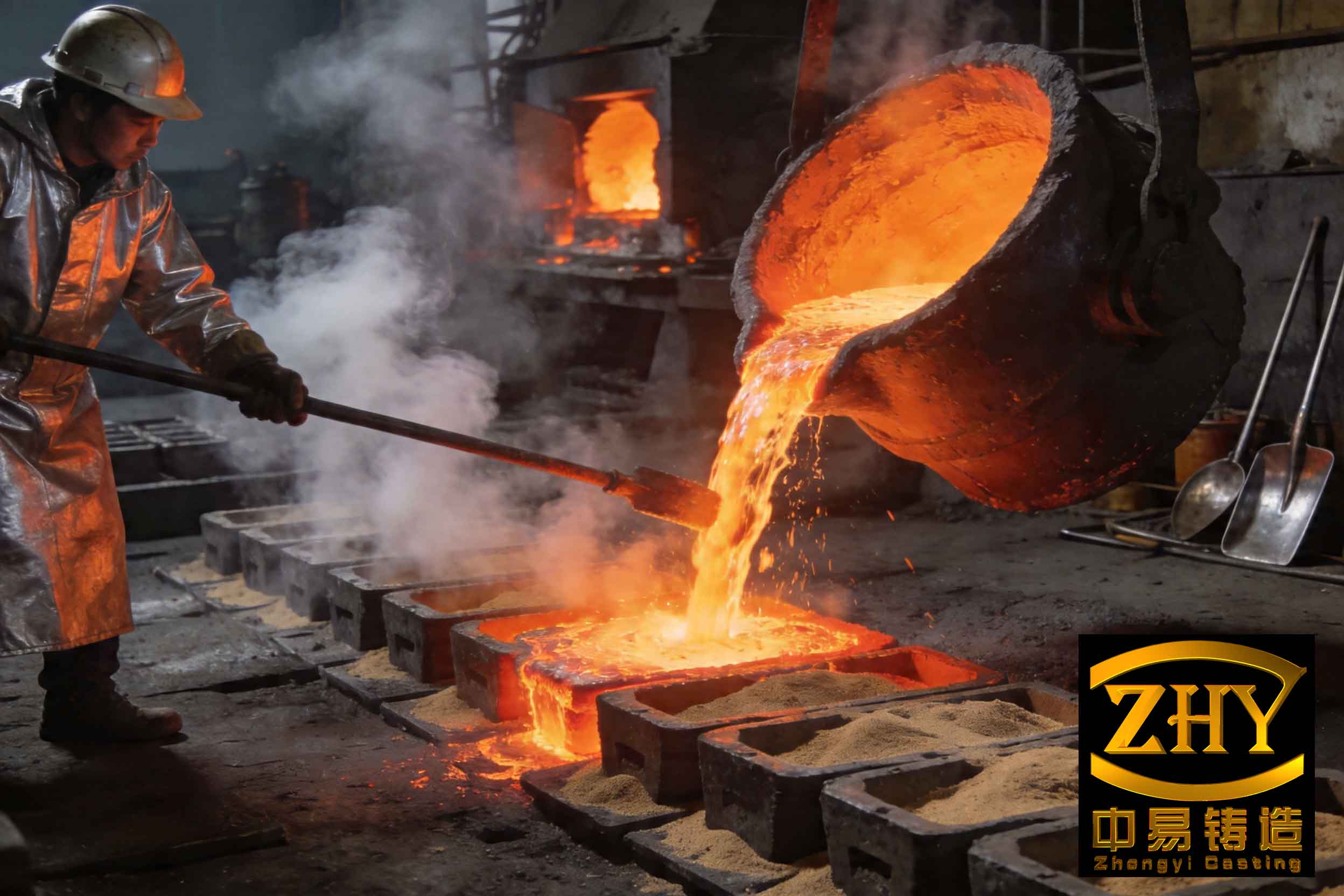
Following a geographical transfer of production, a significant quality issue emerged: recurring slag inclusion defects at specific locations—the transverse bolt bosses on the main bearing cap mating faces (known as the “wa kou”). These defects posed a serious threat to the subsequent machining and assembly integrity of the crankshaft main bearing caps. Visual and microscopic examination revealed non-metallic inclusions embedded in the casting surface at these bosses. Energy Dispersive Spectroscopy (EDS) analysis identified the primary constituents of these inclusions as silicon dioxide (SiO₂) and alumina (Al₂O₃), often accompanied by trace elements like potassium (K) and sodium (Na). This composition profile is characteristic of a dross or slag-type slag inclusion defect, originating from oxidized metal, slag from the furnace, or refractory materials.
Theoretical and Practical Root Cause Analysis
The formation of a slag inclusion defect is governed by the interplay between molten metal cleanliness, fluid flow dynamics, and the gating system’s ability to trap impurities. Our investigation pinpointed three synergistic root causes.
1. Inadequate Metal Cleanliness and Alloy Assimilation: The original melting and treatment practice was a primary contributor. The practice involved placing the primary inoculant (Si-Ba), rare-earth silicon iron, electrolytic copper, ferrochrome, and ferromolybdenum into the bottom of the pouring ladle before tapping the furnace at 1480-1500°C. This method is fundamentally flawed for high-melting-point alloys. For instance, the melting point of ferromolybdenum (FeMo) is approximately 1750-1980°C, far above the tap temperature. The relationship for complete dissolution of an alloy addition can be simplified as:
$$ Q = m \cdot C_p \cdot \Delta T + m \cdot L_f $$
Where \( Q \) is the total heat required, \( m \) is the mass of the addition, \( C_p \) is its specific heat capacity, \( \Delta T \) is the temperature rise needed, and \( L_f \) is its latent heat of fusion. Tapping onto a cold alloy lump in a ladle provides insufficient \( Q \) for complete dissolution within the limited time before pouring. Partially melted or undissolved chunks of these alloys, along with unreacted inoculant, were carried into the mold cavity, creating exogenous slag inclusion defects. Furthermore, the potential use of leftover ductile or compacted graphite iron base iron to adjust chemistry for grey iron introduced unnecessary variability and additional sources of oxides.
2. Unfavorable Flow Dynamics in Horizontal Pouring: The horizontal gating orientation, while solving earlier gas defect problems, created a perfect trap for slag. According to Stokes’ law, the velocity (\( v \)) at which a slag particle rises in molten iron is given by:
$$ v = \frac{2 g r^2 (\rho_{Fe} – \rho_{slag})}{9 \eta} $$
Where \( g \) is gravity, \( r \) is the particle radius, \( \rho \) are the densities of iron and slag, and \( \eta \) is the viscosity of iron. Slag particles, being less dense, tend to float to the top surface of the flowing metal stream. In a horizontal cavity, the top surface of the flow corresponds to the upper parts of the casting. The transverse bolt bosses, located on the upper surface of the heavy, flat casting section, acted as natural “slag pockets.” As the metal front advanced, slag accumulated at these high points in the mold cavity, leading to a localized slag inclusion defect.
3. Ineffective Slag Trapping in the Gating System: The original gating system was a pressurized design without any filtration. While a well-designed pressurized system can promote a smooth, non-turbulent fill, its slag-trapping capability is limited to the action of the sprue well and the velocity changes in the runners. For large castings with high metal volume, this is often insufficient. The absence of a ceramic filter meant that any slag not separated in the pouring basin or sprue well had a direct path into the casting cavity. The system lacked a final, reliable barrier to intercept the slag inclusion defect precursors.
| Root Cause Category | Specific Mechanism | Contribution to Slag Formation |
|---|---|---|
| Metallurgical | Undissolved high-m.p. alloys (FeMo, FeCr) | Direct source of exogenous inclusions |
| Metallurgical | Unmelted/oxidized inoculant | Source of SiO₂ and Al₂O₃ inclusions |
| Process | Insufficient slag skimming after tap | Allows furnace slag transfer to mold |
| Fluid Dynamics | Horizontal filling & top-surface flow | Channels floating slag to high-point features |
| Gating Design | Absence of filtration media | No mechanical barrier to slag entry |
A Multi-Pronged Engineering Solution
Addressing a complex slag inclusion defect required a holistic approach targeting each root cause. The following corrective actions were implemented simultaneously.
1. Comprehensive Overhaul of Melting and Treatment Practice:
- Dedicated Melts: The CW250 iron is now melted as a dedicated heat. The practice of using leftover iron from other grades (e.g., ductile iron) for chemistry adjustment was strictly prohibited to eliminate cross-contamination and unpredictable oxide levels.
- Furnace Alloying: All high-melting-point alloying elements—ferrochromium and ferromolybdenum—are now added directly to the induction furnace. The furnace power is then increased to raise the superheat temperature to a minimum of 1520°C and held for a sufficient time (typically 5-8 minutes) to ensure complete dissolution. This ensures the alloys are in solution before tapping, satisfying the heat requirement equation.
- Inoculation Method Change: The primary Si-Ba inoculation was changed from ladle-bottom addition to a controlled stream inoculation during tapping. This guarantees the inoculant encounters a high-temperature metal stream, promoting immediate dissolution and reaction, thereby minimizing the chance of creating undecomposed inoculant particles that lead to a slag inclusion defect.
- Enhanced Slag Removal: A strict protocol of multiple, thorough slag-offs (skimming) was instituted: once after alloy dissolution in the furnace, immediately after tapping into the ladle, and again just before the ladle is moved to the pouring station.
2. Integration of a Ceramic Foam Filter into the Gating System:
Modifying the existing runner and gate layout was impractical. Instead, the most effective location for a filter was identified at the interface between the pouring basin/sprue box and the downsprue. A rectangular ceramic foam filter with a cellular structure was specified. The critical design parameter was the filter’s effective filtration area, which must be greater than the cross-sectional area of the downsprue to avoid creating a new flow restriction and altering the designed gating ratios. The selection was based on:
$$ A_{filter} = k \cdot A_{sprue} $$
Where \( A_{filter} \) is the minimum required filtration area, \( A_{sprue} \) is the cross-sectional area of the sprue, and \( k \) is a safety factor (typically 1.5 to 2.5). For our system, a filter with \( k \approx 2.0 \) was installed. This filter acts as a perfect mechanical barrier, capturing slag, deoxidation products, and any residual unmelted particles, fundamentally preventing their entry into the casting and eliminating the primary pathway for the slag inclusion defect.
3. Compensatory Machining Allowance Increase:
Recognizing that foundry processes have inherent variability and that the boss location was geometrically susceptible, a strategic decision was made to increase the machining allowance on the transverse bolt bosses. This is a risk-mitigation step. If, under extreme circumstances, a small, sub-surface slag inclusion defect were to form, the increased stock material ensures it will be completely removed during the subsequent machining operation, safeguarding the functional integrity of the part.
| Corrective Action | Targeted Root Cause | Key Implementation Parameter |
|---|---|---|
| Dedicated Furnace Melts | Metal cleanliness / Cross-contamination | 100% dedicated charge for CW250 |
| Furnace Alloying of FeCr & FeMo | Undissolved alloys | Superheat to ≥1520°C, hold >5 mins |
| Stream Inoculation | Undissolved inoculant | Inoculant added during tap stream |
| Enhanced Slag Skimming | Furnace/ladle slag transfer | 3-stage skimming: furnace, post-tap, pre-pour |
| Ceramic Foam Filter Installation | Ineffective gating slag removal | Filter area \(A_{filter} \geq 2.0 \cdot A_{sprue}\) |
| Increased Machining Allowance | Residual risk at critical feature | Boss stock increased by 2-3 mm |
Production Validation and Results
The combined solutions were implemented and validated over an extended production run encompassing more than twenty castings. The results were definitive. The occurrence of the slag inclusion defect at the transverse bolt bosses dropped to zero. Furthermore, indirect benefits were observed:
- Improved Consistency: The furnace alloying practice led to more consistent and predictable alloy recovery rates for chromium and molybdenum, reducing chemical composition variability.
- Enhanced Inoculation Efficiency: The stream inoculation method improved the effectiveness of the primary inoculation, contributing to a more uniform and desirable Type A graphite structure throughout the heavy sections of the casting.
- Reduced Rework and Scrap: The complete elimination of the defect directly translated to a 100% reduction in rework or scrap costs associated with this specific slag inclusion defect, significantly improving the financial yield of the production process for the CW250 block.
| Performance Metric | Status Before Solution | Status After Solution |
|---|---|---|
| Slag Inclusion Defect Rate at Bosses | >30% of castings affected | 0% over >20 castings |
| Alloy Recovery (Cr, Mo) Consistency | High variability (±15%) | Stable, within ±5% |
| Graphite Structure Uniformity | Occasional undercooled graphite in bosses | Consistent Type A, >95% |
| Rework/Scrap Cost for this Defect | Significant | Eliminated |
Conclusion
The successful resolution of the CW250 cylinder block slag inclusion defect underscores a fundamental principle in foundry engineering: critical casting defects are rarely solved by a single, simple adjustment. They are typically the result of systemic interactions between metallurgy, fluid dynamics, and process design. This case study demonstrated that the slag inclusion defect originated from a triad of issues: chemically and physically unclean metal due to poor alloy addition practices, a mold-filling pattern that naturally collected floating impurities at critical locations, and a gating system lacking a final defensive barrier.
The implemented solution package was equally comprehensive. It involved recalibrating the metallurgical process to ensure complete alloy dissolution and clean metal production, redesigning the metal delivery system to include an effective ceramic filter, and applying a prudent risk-mitigation strategy via machining allowances. The filter’s role was particularly crucial, acting as an absolute gatekeeper. The formula for its sizing, ensuring \( A_{filter} = k \cdot A_{sprue} \) with \( k > 1 \), is a critical takeaway for gating design for large castings prone to slag inclusion defects.
This experience conclusively proves that robust process control, coupled with scientifically guided design modifications, can completely eliminate even the most persistent slag inclusion defects. The lessons learned—particularly regarding the treatment of high-melting-point alloys and the non-negotiable need for effective filtration in heavy casting production—have been integrated into our standard foundry practice, leading to more reliable and cost-effective manufacturing of high-integrity cast components.