
In my extensive involvement with foundry operations, particularly in the continuous casting of steel wheels using bottom pouring ladles, I have consistently encountered a persistent and规律性 issue: the formation of slag inclusion defects. These defects manifest as non-metallic inclusions within the castings, severely compromising their mechanical integrity, fatigue life, and overall quality. The problem exhibits a distinct, reproducible pattern that is independent of seasonal variations, presenting a major bottleneck for production efficiency, cost control, and scrap rate management. This article presents a detailed, first-person analysis of this phenomenon, rooted in fluid dynamics principles, and proposes practical solutions to mitigate the slag inclusion defect. Throughout this discussion, the term ‘slag inclusion defect’ will be emphasized to underscore its central role in the casting challenges faced.
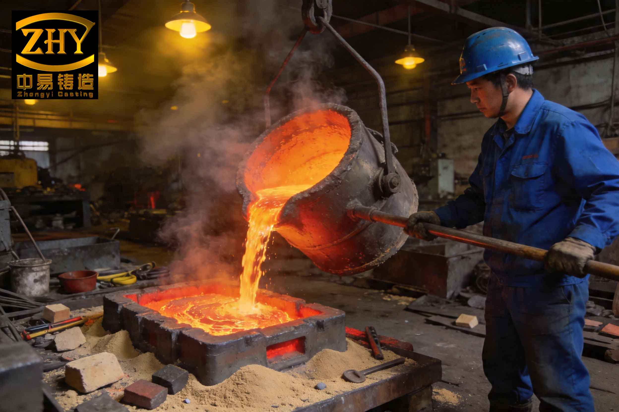
The typical process, as I have operated it, involves melting scrap steel in an electric arc furnace, followed by refining, alloy adjustment, and tapping into a 5-ton bottom pouring ladle. The final composition is tuned within the ladle using ferrosilicon, electrolytic manganese, carbon, and aluminum. The steel, at a pouring temperature of 1580–1600°C, is then continuously cast into molds for wheels, each weighing approximately 80 kg. A single ladle yields about 100 wheels across 25 molds. Despite stringent control over charge materials, furnace practice, and mold preparation (using CO2-hardened sodium silicate sand, dried in an oven), a规律性 pattern of slag inclusion defect occurrence was undeniable.
The statistical behavior of the slag inclusion defect was striking and demanded explanation. The key observations were: first, the first mold poured from each ladle consistently exhibited a higher scrap rate due to slag inclusion defect. Second, following a mold with a high scrap rate from slag inclusion defect, the subsequent mold invariably showed a lower scrap rate. Third, over the course of pouring seven consecutive ladles, the scrap rate of the first mold from each ladle showed a progressive increase. Finally, the average scrap rate per ladle also increased progressively across the seven ladles. This pattern ruled out random causes such as sporadic mold sand erosion or batch-to-batch variations in melt chemistry, which would produce a more stochastic distribution of the slag inclusion defect.
My initial investigation systematically eliminated conventional culprits. The quality of refractory materials in the ladle, while crucial, could not singularly explain the immediate fluctuation between high and low scrap rates. Operator error was unlikely to create such a consistent,跨-seasonal规律性. The inherent gas and slag content of the steel melt, though influential, was controlled within tight limits and could not account for the precise inter-pour and inter-ladle trends observed. This led me to hypothesize that the root cause was embedded within the fundamental physics of the pouring process itself—specifically, the fluid dynamics of liquid metal flow through the ladle’s nozzle.
The core of my analysis lies in applying fluid mechanics to the bottom pouring system. The ladle functions as a large reservoir with a vertical nozzle (stopper-rod controlled) at its base. As steel flows out, the change in cross-sectional area and flow velocity induces pressure variations. Using Bernoulli’s principle for steady, incompressible flow, I analyzed the pressure at a critical contraction plane within the nozzle.
Consider the ladle system with a free surface (plane D-D) and the narrowest part of the nozzle (plane C-C). Taking a horizontal reference plane (1-1) at the nozzle exit, Bernoulli’s equation between D-D and 1-1 is:
$$H + \frac{P_D}{\gamma} + \frac{\alpha_D V_D^2}{2g} = 0 + \frac{P_1}{\gamma} + \frac{\alpha_1 V_1^2}{2g} + \Sigma \xi \frac{V_1^2}{2g}$$
Where:
– $H$ is the metal head height above the reference,
– $P_D$ and $P_1$ are pressures at D-D and 1-1,
– $V_D$ and $V_1$ are velocities,
– $\alpha_D$ and $\alpha_1$ are kinetic energy correction factors (≈1 for turbulent flow),
– $\gamma$ is the specific weight of steel ($\gamma = \rho g \approx 7600 \, \text{kg/m}^3 \times 9.81 \, \text{m/s}^2 \approx 74556 \, \text{N/m}^3$),
– $g$ is gravitational acceleration,
– $\Sigma \xi$ is the sum of local resistance coefficients for the nozzle.
Since the free surface area is much larger than the nozzle area, $V_D \approx 0$. Both $P_D$ and $P_1$ are atmospheric pressure for the free surface and jet exit, so $P_D = P_1$. The equation simplifies to:
$$H = (\alpha_1 + \Sigma \xi) \frac{V_1^2}{2g}$$
Solving for exit velocity $V_1$:
$$V_1 = \frac{\sqrt{2gH}}{\sqrt{\alpha_1 + \Sigma \xi}} = \phi \sqrt{2gH}$$
where $\phi = 1/\sqrt{\alpha_1 + \Sigma \xi}$ is the velocity coefficient. For a standard sharp-edged orifice, typical values are $\xi_{\text{entry}} = 0.5$, $\xi_{\text{friction}} \approx 0.02 L/d$, leading to $\Sigma \xi \approx 0.53$. With $\alpha_1=1$, $\phi \approx 0.81$.
The crucial insight comes from examining the pressure at the vena contracta (plane C-C), just inside the nozzle where the flow area is minimal. Applying Bernoulli’s equation between D-D and C-C:
$$H + \frac{P_D}{\gamma} + \frac{\alpha_D V_D^2}{2g} = h_c + \frac{P_C}{\gamma} + \frac{\alpha_C V_C^2}{2g} + \xi_{\text{entry}} \frac{V_C^2}{2g}$$
Here, $h_c$ is the vertical distance from the reference to plane C-C. With $V_D=0$, $\alpha_C=1$, and using continuity $A_1 V_1 = A_C V_C$ (where $A$ denotes area), we derive the pressure difference:
$$\frac{P_D – P_C}{\gamma} = \left[ \left(\frac{\phi}{\epsilon}\right)^2 (1 + \xi_{\text{entry}}) – 1 \right] H + h_c$$
where $\epsilon = A_C / A_1$ is the contraction coefficient (≈0.64 for a sharp orifice). Substituting values $\phi=0.81$, $\epsilon=0.64$, $\xi_{\text{entry}}=0.5$:
$$\frac{P_D – P_C}{\gamma} \approx 0.70H + h_c$$
Since $P_D$ is atmospheric pressure, $P_C$ is lower; a vacuum (negative gauge pressure) exists at plane C-C. The vacuum degree is:
$$P_{\text{vac}} = P_D – P_C = \gamma (0.70H + h_c)$$
This equation reveals two critical aspects: first, the vacuum is directly proportional to the metal head $H$. As the ladle empties, $H$ decreases linearly, so the vacuum decreases linearly during pouring. Second, at any given $H$, a significant vacuum exists inside the nozzle. For a typical initial head of $H=1.5 \, \text{m}$ and $h_c=0.1 \, \text{m}$, $\gamma \approx 74556 \, \text{N/m}^3$, the initial vacuum is:
$$P_{\text{vac, initial}} = 74556 \times (0.70 \times 1.5 + 0.1) \approx 74556 \times 1.15 \approx 85739 \, \text{Pa} \approx 0.85 \, \text{atm}$$
This substantial sub-atmospheric pressure within the nozzle has a profound effect on the molten steel. Gases dissolved in the steel (such as nitrogen, hydrogen) become supersaturated under this vacuum and nucleate into bubbles. These bubbles act as excellent collectors for non-metallic inclusions—deoxidation products (Al₂O₃, SiO₂, MnO), eroded refractories, and reoxidation scum. The bubbles, laden with slag particles, migrate to the nozzle wall where the pressure is lowest (due to the velocity profile, wall static pressure is lower than the core pressure). They coalesce and adhere to the refractory surface, forming a porous, slag-rich layer. This layer grows with continuous flow until the shear stress from the high-velocity steel exceeds its adhesive strength, causing patches to detach and be carried into the mold cavity. This discrete, intermittent detachment is the primary source of the macroscopic slag inclusion defect in the castings.
The fluid dynamic model perfectly explains the observed规律性 of the slag inclusion defect. Let me elaborate: For the first mold from a full ladle, the head $H$ is maximum, hence the vacuum $P_{\text{vac}}$ is highest. This promotes intense gas nucleation and slag adhesion. Early in the pour, the nozzle wall is relatively clean, so the initial slag layer builds up and is likely to detach during this first fill, leading to a high incidence of slag inclusion defect. Once a major detachment event occurs (resulting in a high-scrap mold), the nozzle wall is temporarily cleaner, making immediate re-accumulation less likely. Therefore, the next mold experiences a lower vacuum effect and a lower scrap rate from slag inclusion defect—explaining the alternating pattern. Over multiple ladles, the refractory nozzle undergoes thermal fatigue and erosion. Its surface becomes rougher, providing more nucleation sites and stronger adhesion for the slag layer. Consequently, the severity of the slag inclusion defect escalates with each successive ladle, manifesting as progressively higher scrap rates for both the first mold and the ladle average. This is a self-reinforcing cycle driven by the vacuum mechanism and refractory degradation.
To formalize the relationship between process parameters and the propensity for slag inclusion defect formation, I developed the following conceptual model, summarized in the table below. The key variables are metal head, nozzle geometry, and steel cleanliness.
| Parameter | Symbol | Effect on Vacuum $P_{\text{vac}}$ | Effect on Slag Inclusion Defect Risk |
|---|---|---|---|
| Metal Head Height | $H$ | $P_{\text{vac}} \propto H$ | Higher head increases vacuum, promoting slag bubble nucleation and adhesion, raising slag inclusion defect risk. |
| Nozzle Diameter | $d$ | Affects $\Sigma \xi$ and $\epsilon$; smaller $d$ increases $V_1$, altering $P_{\text{vac}}$. | Smaller diameter increases velocity and shear, may enhance detachment frequency of slag layers, affecting slag inclusion defect size and distribution. |
| Nozzle Length | $L$ | Increases friction loss $\xi_{fric} = \lambda L/d$. | Longer nozzle increases total pressure drop, can slightly modify $P_{\text{vac}}$ profile, influencing where in the nozzle slag deposition occurs. |
| Steel Gas Content | $[G]$ | Not directly affecting $P_{\text{vac}}$. | Higher dissolved gas provides more bubble nuclei under vacuum, directly increasing slag capture and slag inclusion defect volume. |
| Inclusion Load | $[I]$ | No effect. | Higher initial inclusion concentration provides more material for bubbles to collect, exacerbating the slag inclusion defect problem. |
| Pouring Temperature | $T$ | Affects $\gamma$ (density) and viscosity. | Lower temperature increases viscosity, may reduce bubble floatation and enhance wall adhesion, complicating slag inclusion defect dynamics. |
The mathematical derivation can be extended to predict the critical conditions for slag layer detachment. Assuming the adhered slag layer behaves as a viscoelastic film, detachment occurs when the fluid shear stress $\tau_w$ exceeds the adhesive strength $\sigma_a$. The wall shear stress in turbulent pipe flow is approximated by:
$$\tau_w = \frac{f}{8} \rho V^2$$
where $f$ is the Darcy friction factor. The average flow velocity in the nozzle $V = Q/A$, with $Q$ being the volumetric flow rate. From the earlier analysis, $V_1 = \phi \sqrt{2gH}$. The friction factor $f$ depends on Reynolds number and wall roughness. As the slag layer builds, it increases effective roughness, altering $f$ and the local flow field, creating a feedback loop. This complexity means the slag inclusion defect release is quasi-periodic, matching the observed fluctuation pattern.
To mitigate the slag inclusion defect, two divergent philosophies can be adopted, each with distinct mechanisms and outcomes. The first strategy is to enhance the vacuum-induced separation effect but actively remove the separated slag before it enters the mold. The second is to suppress or weaken the vacuum effect to prevent localized slag accumulation, thereby dispersing inclusions (though this may harm mechanical properties). I have experimented with and evaluated numerous techniques under both categories.
Strategy 1: Strengthen Separation and Actively Remove Slag
This approach acknowledges the vacuum’s power to aggregate slag but intercepts the aggregates. Methods include:
- Nozzle with Internal Filter/Expansion Chamber: Modifying the standard cylindrical nozzle to include a sudden expansion or a porous ceramic filter plate within its length. The expansion reduces flow velocity, promoting buoyant rise of slag-laden bubbles into a catchment zone. The filter physically traps larger aggregates. The flow can also be imparted a swirl via helical grooves (rifling) to use centrifugal force for slag separation. The separation efficiency $\eta_s$ for a swirl chamber can be modeled by Stokes’ law modified for centrifugal acceleration:
$$\eta_s = 1 – \exp\left(-\frac{2 \pi N \omega^2 r_c \Delta \rho d_p^2}{9 \mu Q}\right)$$
where $N$ is number of turns, $\omega$ angular velocity, $r_c$ chamber radius, $\Delta \rho$ density difference between inclusion and steel, $d_p$ inclusion diameter, $\mu$ viscosity, $Q$ flow rate. - Enhanced Ladle Metallurgy: Performing more vigorous gas stirring (e.g., argon through a porous plug in the ladle bottom) after tapping to float out inclusions before pouring. This reduces the initial inclusion load $[I]$, diminishing the feedstock for vacuum-driven aggregation.
- Modified Pouring Basin/Runner: Designing the sprue cup or runner with a whirl gate or dam that induces a vortex; inclusions migrate to the vortex core and are trapped. Delaying the flow into the mold by using a thin steel sheet melt barrier allows time for flotation.
Strategy 2: Weaken the Vacuum Effect to Disperse Inclusions
This approach aims to minimize the pressure drop and slag layer formation, accepting finer, more dispersed inclusions. Techniques include:
- Venting the Nozzle: Using permeable refractory for the nozzle or machining longitudinal vents/channels along its inner wall to equalize pressure, reducing $P_{\text{vac}}$. This can be quantified by adding a pressure relief term to the Bernoulli equation. If a vent provides a direct path to atmosphere at pressure $P_a$, the pressure at C-C becomes $P_C’ = P_a – \Delta P_{\text{vent}}$, where $\Delta P_{\text{vent}}$ is the pressure loss through the vent. This raises $P_C$, reducing the driving force for gas nucleation.
- Optimized Nozzle Geometry: Designing a nozzle with a streamlined, tapered profile (convergent-divergent) to minimize flow separation and turbulence, thereby reducing the local pressure dip. The wall contour should follow a potential flow streamline to maintain attached flow and minimize the vena contracta effect.
- Reduced Pouring Height: Lowering the ladle closer to the mold reduces the initial head $H$, directly decreasing $P_{\text{vac}}$ per the equation $P_{\text{vac}} \propto H$. However, this may reduce filling pressure and require reevaluation of gating design.
- Increased Nozzle Diameter: A larger diameter reduces flow velocity $V_1$ for the same $H$, which reduces shear stress and may allow a more stable, non-detaching slag film. However, this also increases the exposed refractory area for adhesion.
The choice between strategies depends on the allowable inclusion level and the criticality of the casting. For high-integrity components like wheels, Strategy 1 is generally preferred. The table below compares key methods.
| Method | Category | Mechanism | Impact on Slag Inclusion Defect | Potential Drawbacks |
|---|---|---|---|---|
| Swirl Chamber Nozzle | Strengthen & Separate | Centrifugal force separates slag bubbles; collects them in central well. | Significantly reduces macro slag inclusion defect count and size. | Increased complexity, cost, potential for nozzle clogging. |
| Porous Filter Insert | Strengthen & Separate | Physical interception of inclusions > filter pore size. | Effective for large slag inclusion defect prevention. | Flow restriction, thermal shock to filter, cost. |
| Argon Stirring in Ladle | Strengthen & Separate | Reduces initial inclusion content [I] via flotation. | Reduces source material for slag inclusion defect formation. | Requires additional equipment, may increase gas pickup if not controlled. |
| Vented Nozzle | Weaken & Disperse | Reduces vacuum $P_{\text{vac}}$ by pressure equalization. | Prevents localized heavy slag accumulation, may disperse inclusions finely. | May lead to more numerous but smaller inclusions, degrading fatigue properties; risk of air aspiration. |
| Streamlined Nozzle | Weaken & Disperse | Minimizes flow separation and pressure drop. | Reduces slag bubble nucleation sites, lessens slag inclusion defect severity. | Precision manufacturing required; limited effect if gas content is high. |
| Reduced Pouring Head | Weaken & Disperse | Lowers H, directly decreasing $P_{\text{vac}}$. | Linear reduction in driving force for slag inclusion defect formation. | May necessitate changes in gating to maintain fill rate; practical limits in shop layout. |
Implementing these solutions requires a holistic view of the process. For instance, combining a slightly vented nozzle with a swirl basin in the runner can both mitigate vacuum nucleation and provide a final separation stage. The effectiveness can be monitored by measuring the slag inclusion defect frequency through radiographic inspection or ultrasonic testing, and correlating it with process parameters. A dimensionless number, which I term the Slag Inclusion Potential (SIP), can be derived to guide practice:
$$\text{SIP} = \frac{P_{\text{vac}} \cdot [G] \cdot [I]}{\mu \cdot V_{\text{cast}}}$$
where $V_{\text{cast}}$ is the casting solidification rate. Lower SIP values indicate a reduced propensity for macroscopic slag inclusion defect formation. Process optimization aims to minimize SIP through controlling head height, steel cleanliness, and nozzle design.
In conclusion, my first-hand investigation into the规律性 slag inclusion defect problem in continuously cast steel wheels via bottom pouring ladles has unequivocally identified the fluid dynamics of pouring as the root cause. The vacuum generated at the nozzle’s vena contracta, proportional to the metal head, triggers gas bubble nucleation and slag particle agglomeration on the nozzle wall. The cyclical buildup and detachment of this slag layer produce the characteristic pattern of slag inclusion defect occurrence. This understanding, grounded in Bernoulli’s principle and mass transfer, provides a powerful framework for addressing the issue. Two strategic paths exist: one harnesses the vacuum effect to concentrate and remove slag before it enters the mold, while the other suppresses the vacuum to disperse inclusions. The former is generally superior for high-quality castings, as it actively eliminates the slag inclusion defect source. Ultimately, controlling the slag inclusion defect requires a synergy of fluid dynamics insight, refractory engineering, and process control, transforming a persistent defect into a manageable variable. The recurrence of the slag inclusion defect can be systematically minimized, leading to improved yield, reliability, and performance of cast steel wheels.