
In the production of high-integrity investment castings, particularly for critical components like valves and flanges where sealing performance is paramount, the occurrence of slag and non-metallic inclusion defects represents a significant and persistent challenge. From my extensive experience in precision foundry operations, I have observed that these slag inclusion defects are not merely surface imperfections. They are volumetric flaws that degrade the pressure tightness, reduce impact toughness and fatigue strength, and can lead to catastrophic failures in service due to leakage. The battle against these defects is fought on multiple fronts, requiring a holistic approach that integrates intelligent process design with meticulous control over every stage of production, from pattern making to final pouring. This article details the systematic methodology I employ to minimize and control these detrimental slag inclusion defects.
The genesis of a slag inclusion defect in a finished casting can often be traced back to decisions made at the very beginning of the process chain. A fundamental principle I adhere to is that the sealing surface of a valve body, seat, or flange must never be positioned to become the primary “dross collection surface” during solidification. When the sealing face is oriented upwards in the mold, it acts as a natural trap for lighter oxides and slag particles floating up from the molten metal. To circumvent this, I prioritize a side-gating or inverted gating strategy for such components. This ensures that critical sealing surfaces are on the sidewalls of the mold cavity, not the top, thereby drastically reducing the risk of slag accumulation on these vital areas.
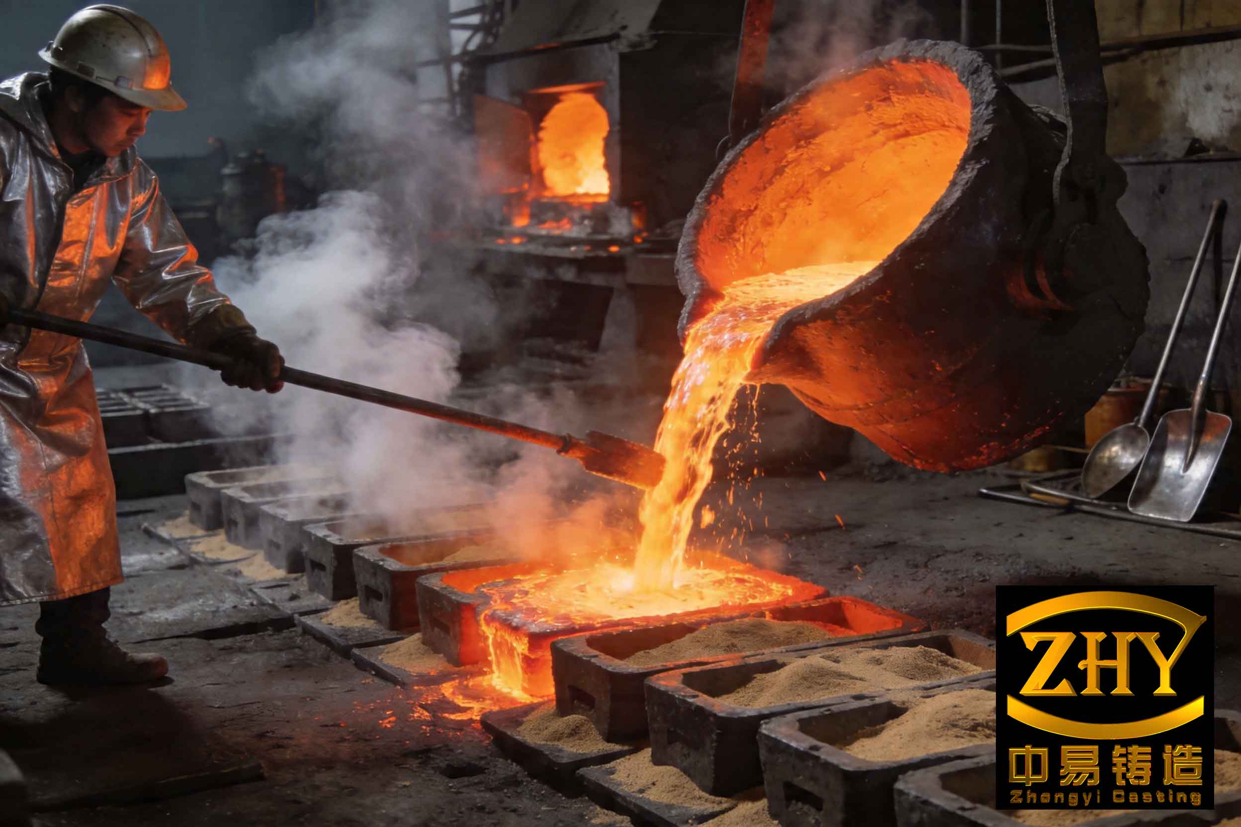
However, process constraints such as the need for directional solidification for soundness sometimes make it unavoidable to have a sealing surface oriented upwards. In these unavoidable scenarios, I implement one of two countermeasures. The first is to deliberately increase the machining allowance on that upward-facing surface. This added material volume is designated as a “sacrificial dross zone.” Any slag inclusion defects that float to the top are contained within this zone and are completely removed during subsequent machining, revealing a pristine, defect-free sealing surface underneath. The second strategy involves designing and attaching small, dedicated “slag traps” or “scum risers” at the highest points of the casting, particularly on non-critical areas like the outer diameters of flanges. These traps are designed to attract and contain floating slag, which is later removed by grinding or cutting. The effectiveness of this approach can be conceptualized by considering the buoyancy force driving slag particles to the highest point. By providing an engineered high point (the trap), we control the final location of the slag inclusion defects.
The journey to a clean casting begins long before metal is melted. Contamination introduced during the wax pattern and shell-building stages can manifest as exogenous slag inclusion defects. A rigorous wax management system is therefore non-negotiable. Recycled wax must undergo a comprehensive process of dewaxing, filtration, and homogenization to remove all particulate contaminants. Any impurities in the wax pattern will be faithfully replicated in the ceramic shell and subsequently in the metal casting. Furthermore, after the autoclave dewaxing process, the fragile shell is highly susceptible to contamination. I enforce strict protocols where all shell clusters are stored and transported with the pour cup facing downwards. For clusters that cannot be inverted, the pour cup is immediately sealed with a protective cap after dewaxing to prevent any foreign material—dust, loose sand, debris—from falling into the pristine cavity. A single piece of stray ceramic can become a major slag inclusion defect.
The selection of raw charge materials has a profound, yet often underestimated, impact on the formation of endogenous slag inclusion defects. To quantify this, I conducted a comparative study using different forms of 304 stainless steel charge.
| Charge Material Form | Description | Oxidation Potential | Observed Slag Defect Severity on Castings |
|---|---|---|---|
| Baled Scrap (Briquettes) | Compacted machining turnings and thin-gauge scraps. | Very High. Large surface-area-to-volume ratio, severe oxidation during melting. | High frequency of severe slag patches and pinholes. |
| Plate & Block Sections | Sheared plates or cast riser cuts with substantial thickness. | Moderate to Low. Smaller surface area, slower, more controlled melting. | Significantly reduced slag; often none visible. |
The baled scrap, due to its high surface area, undergoes intense oxidation during the initial heating and melting phase, generating a large volume of primary oxide slag. This slag, if not perfectly removed, becomes a direct source of slag inclusion defects. Therefore, for castings requiring high sealing integrity, I mandate the use of dense, low-surface-area charge materials like plate or block sections to minimize the initial slag generation at source.
The heart of the battle against slag inclusion defects is won or lost in the melting furnace. A disciplined, multi-stage deoxidation practice is the most critical weapon. The goal is to manage the oxygen content in the molten steel and facilitate the formation, growth, and removal of deoxidation products before the metal enters the mold cavity. The chemical thermodynamics are guided by principles like the formation of low-melting-point, easily removable complex oxides.
For carbon and low-alloy steels, the sequence of addition is crucial. I follow a “weak to strong” deoxidation hierarchy. Manganese (added as ferromanganese) is added first as a pre-deoxidizer:
$$ [Mn] + [O] \rightarrow (MnO) $$
The manganese oxide (MnO) formed has a high melting point (~1850°C). Subsequently, silicon (as ferrosilicon) is added:
$$ [Si] + 2[O] \rightarrow (SiO_2) $$
The key reaction, however, is between the products:
$$ (MnO) + (SiO_2) \rightarrow (MnO \cdot SiO_2) $$
This manganese silicate (MnO·SiO₂) has a much lower melting point (approximately 1290°C), coaleces into larger droplets, and readily floats to the surface for removal. Following this, I employ a powerful complex deoxidizer like silicon-calcium-manganese. Calcium is an extremely strong deoxidizer and also modifies the morphology of any remaining alumina or silicate inclusions, making them globular and less harmful. Finally, a small amount of aluminum (as wire) is used for a final “kill” or blocking deoxidation just before tap to prevent re-oxidation during transfer. The reaction is rapid and highly exothermic:
$$ 2[Al] + 3[O] \rightarrow (Al_2O_3) $$
For stainless steels like 304 or 316, where aluminum cannot be used (to avoid precipitating aluminum nitrides and affecting corrosion resistance), the reliance on silicon and complex deoxidizers is greater, often requiring multiple additions during a holding period to allow for diffusion and flotation.
| Steel Family / Typical Grade | Key Deoxidants & Typical Addition Sequence | Process Window & Notes |
|---|---|---|
| Carbon & Low-Alloy Steels (e.g., 0.2-0.4% C) | 1. FeMn (Pre-deox.) 2. FeSi 3. Si-Ca-Mn (0.10-0.15%) 4. Al wire (0.06-0.10%) |
FeMn added at ~80% melt. Final deox. at 1500-1550°C. Slag-off after each stage. Al added last before tap. |
| Stainless Steels Austenitic (e.g., 304, 316) | 1. Electrolytic Mn (Pre-deox.) 2. Si-Ca-Mn (0.2-0.3% total, in 2 steps) |
No Al. Pre-deox. at 80% melt. First Si-Ca-Mn at 1550-1580°C, hold for slag floatation. Second addition after slag-off, then final temperature rise and pour. |
Pouring temperature is a powerful, yet double-edged, parameter in controlling slag inclusion defects. A temperature that is too low leads to high metal viscosity, preventing the buoyant slag particles from floating to the top of the casting or the riser. They become trapped within the solidifying metal matrix. Conversely, an excessively high temperature can increase metal oxidation and reaction with the mold. I have empirically established an optimal range. For a typical CF8M (316 stainless) valve body, increasing the pouring temperature from 1565°C to 1645°C resulted in a dramatic visual improvement: severe slag patches at the lower temperature transitioned to a completely clean casting at the higher temperature. The increased superheat provides the thermal energy and time necessary for Stokes’ law flotation:
$$ v = \frac{2 g r^2 ( \rho_m – \rho_s )}{9 \eta} $$
where \( v \) is the terminal velocity of the slag particle, \( g \) is gravity, \( r \) is the particle radius, \( \rho_m \) and \( \rho_s \) are the density of metal and slag respectively, and \( \eta \) is the metal viscosity. Higher temperature reduces \( \eta \), directly increasing \( v \), allowing slag to escape the casting body more efficiently.
An often-overlooked source of surface-connected slag inclusion defects, especially in low-alloy and martensitic stainless steels, is a metallurgical reaction between the molten metal and the ceramic shell’s face coat. Steels with low levels of strong oxide formers (like Si, Al) are particularly susceptible. When such steel is poured against a zircon flour/sand-based face coat (which contains significant free silica, SiO₂), a high-temperature interfacial reaction can occur:
$$ [Fe] + (SiO_2) \rightarrow [FeO] + [Si] $$
$$ [FeO] + (SiO_2) \rightarrow (FeO \cdot SiO_2) \text{ (Fayalite)} $$
The silicon can be absorbed into the metal, and the iron silicate slag wets and penetrates the casting surface, creating rough, pitted “reaction scabs” or a speckled appearance that compromises sealing. To combat this, I specify a high-purity alumina (Al₂O₃) based face coat material for casting low-alloy, martensitic, and carbon steels. Alumina is chemically more stable and inert towards molten iron alloys, virtually eliminating this type of surface reaction defect. A simple comparative test casting of a 1.4008 (CA-6NM type) martensitic stainless component showed a stark contrast: the zircon-shell casting had severe surface reaction and slag pitting, while the alumina-shell casting was smooth and free from such defects.
| Casting Material Type | Recommended Face Coat | Rationale |
|---|---|---|
| Carbon Steels, Low-Alloy Steels, Martensitic Stainless Steels (e.g., 1.4008, 410, CA-6NM) | High-Purity White Fused Alumina (Al₂O₃ > 99%) | Chemically inert. Prevents metal-mold reaction and the formation of low-melting-point iron silicate slags at the interface. |
| Austenitic Stainless Steels (304, 316, etc.), High-Alloy Steels | Zircon (ZrSiO₄) or High-Alumina | These alloys have sufficient Si/Cr to form a protective layer. Zircon provides excellent surface finish and refractoriness. |
In conclusion, the eradication of slag inclusion defects in precision investment castings is not achievable through a single silver-bullet solution. It is the cumulative result of a disciplined, system-wide philosophy. It begins with intelligent process design that strategically manages solidification and slag flotation paths. It is reinforced by flawless execution in the wax room and shell shop to prevent exogenous contamination. It is decisively controlled in the melt shop through the scientific application of deoxidation thermodynamics, careful charge selection, and optimal pouring temperature. Finally, it is protected by selecting the correct mold interface chemistry. Each of these elements forms a link in a chain. By strengthening every link through standardized procedures, continuous monitoring, and a deep understanding of the underlying metallurgical and physical principles, I have consistently achieved the production of high-integrity castings with the exceptional sealing performance demanded by the most critical applications. The systematic mitigation of slag inclusion defects is, therefore, a fundamental cornerstone of quality in the investment casting process.