
In my extensive experience within the foundry industry, the production of high-integrity cast steel components, particularly wheels for heavy-duty applications like overhead cranes, presents significant challenges. Among the most persistent and costly issues are internal gas porosity and, critically, slag inclusion defects. These defects manifest as cavities or non-metallic inclusions within the casting matrix, severely compromising mechanical properties such as fatigue strength and toughness, leading to premature failure in service. This article provides a comprehensive, first-person analysis of the formation mechanisms for these defects, synthesizing theoretical principles with practical insights, and proposes a systematic set of verified preventative measures. The core of the discussion will revolve around process parameters, fluid dynamics, and material science, with a particular emphasis on understanding and mitigating slag inclusion defects.
1. Characterization of Defects and Foundry Process Context
The typical defects observed are not singular in nature. Gas pores can appear as isolated spherical or elongated cavities, often located in the lower sections of the wheel rim or web. Slag inclusion defects, more problematic for structural integrity, appear as irregular, dark-colored inclusions often accompanied by oxide films or sand particles. Their presence in machined surfaces is unacceptable. The original manufacturing process for these wheels can be summarized as follows:
- Molding: Sodium silicate (water glass) sand, hardened with CO2 and subsequently oven-dried.
- Coating: Alcohol-based zirconia paint applied to the mold cavity.
- Melting & Pouring: Electric arc furnace melting, followed by bottom-pour (teapot) ladle casting.
- Gating System: A single sprue connected to one horizontal runner and one ingate, introducing metal tangentially at the parting plane. The casting was located in the drag, with multiple top risers for feeding.
- Key Parameters: Pouring temperature range of 1560-1580°C, with a total pouring time for the wheel cavity (excluding risers) of approximately 90 seconds for a medium-sized wheel.
The initial reject rate due to these combined defects was alarmingly high, between 15-20%, and could exceed 30%, indicating fundamental flaws in the process.
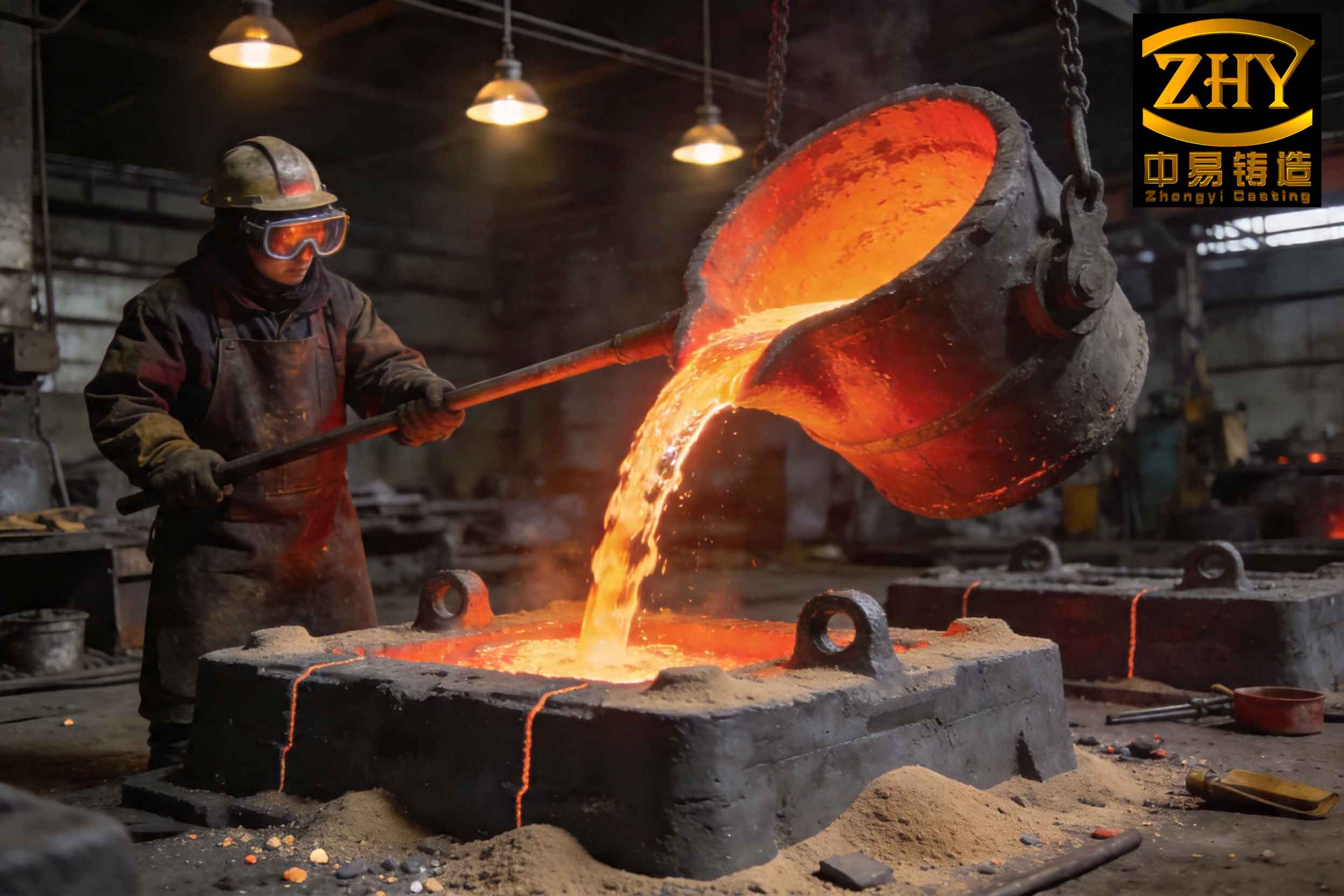
The image above provides a clear visual reference for the typical morphology of slag inclusion defects within a cast structure, highlighting their irregular and detrimental nature.
2. Formation Mechanisms: A Root Cause Analysis
The genesis of both gas porosity and slag inclusion defects lies in the interplay between molten metal, the mold environment, and the dynamics of the filling process.
2.1 Sources of Gas and Inclusion Formation
The potential sources are multifaceted and can be categorized as follows:
| Source | Description | Resulting Defect Type |
|---|---|---|
| Mold/Gas Evolution | Moisture vaporization, combustion of organic binders, and gas generation from reactions between metal and mold coating. Gas pressure (Pgas) builds at the metal-mold interface. | Blowholes, Pinhole Porosity |
| Molten Steel Decomposition | Dissolved gases (H2, N2) originating from charge materials, atmosphere, and slag during melting. Solubility drop upon solidification causes gas precipitation. | Microporosity, Shrinkage-gas combined defects |
| Oxidation/Turbulent Pouring | Entrainment of air and mold atmosphere due to turbulent flow. Reaction of molten steel with oxygen to form oxides (FeO, MnO, SiO2). Erosion of mold sand. | Slag inclusion defects, Oxide films, Sand inclusions, Macro-porosity |
| Ladle/Refractory | Erosion of ladle lining or nozzle refractory material, introducing exogenous particles. | Exogenous slag inclusion defects |
The fundamental condition for gas invasion is given by:
$$P_{\text{gas}} > P_{\text{metal}} + P_{\text{atm}} + \frac{2\gamma}{r}$$
where \(P_{\text{gas}}\) is the gas pressure at the interface, \(P_{\text{metal}}\) is the metallostatic pressure, \(P_{\text{atm}}\) is atmospheric pressure, \(\gamma\) is the surface tension of the steel, and \(r\) is the pore radius. If this condition holds during filling or solidification, gas will penetrate the liquid metal.
2.2 Critical Analysis of the Original Process
The original process contained several inherent flaws that promoted defect formation:
Excessively Long Pouring Time & Low Fill Rate: The bottleneck was the small ladle nozzle diameter (Ø30 mm). For a wheel weighing several hundred kilograms with a height \(H\) of ~200 mm, the actual cavity fill time \(t_f\) was ~90 s. The upward fill rate \(v_f\) is a critical parameter:
$$v_f = \frac{H}{t_f}$$
For this case, \(v_f \approx 2.2 \text{ mm/s}\). This is far below the recommended minimum fill rate for steel castings of similar section thickness, which is typically >10 mm/s. While a slow fill rate can allow for gas buoyancy, an excessively low \(v_f\) has catastrophic consequences:
- Severe Temperature Drop: Prolonged exposure leads to excessive superheat loss, significantly increasing metal viscosity \(\mu\).
- Enhanced Oxidation: A large, exposed metal surface area in the gating system and mold promotes oxide formation.
The increased viscosity drastically reduces the buoyant velocity \(v_b\) of gas bubbles and non-metallic particles (a primary source of slag inclusion defects), as described by Stokes’ law for small spherical inclusions:
$$v_b = \frac{2 g r^2 (\rho_m – \rho_i)}{9 \mu}$$
where \(g\) is gravity, \(r\) the particle/bubble radius, \(\rho_m\) the metal density, and \(\rho_i\) the inclusion density. Despite the presence of top risers intended as collection points, the high viscosity prevented inclusions and bubbles from floating over the significant distance to the top, trapping them in the lower parts of the wheel cavity. This explains the subsurface location of many defects.
Uncontrolled, Turbulent Filling: The gating system was poorly designed. With a single tangential ingate at the parting line and the casting in the drag, it constituted an uncontrolled top-pouring system. The area ratios (\(A_{\text{sprue}}:A_{\text{runner}}:A_{\text{ingate}}\)) were nearly equal, rather than being progressively larger to create a pressurized but non-turbulent or an unpressurized (choke-at-bottom) system. This caused metal to enter the mold cavity with high velocity, leading to splashing and severe turbulence. Turbulence is quantified by the Reynolds number \(Re\):
$$Re = \frac{\rho v D}{\mu}$$
where \(v\) is velocity and \(D\) is hydraulic diameter. High \(Re\) (>2000 for channel flow) indicates turbulent flow, which entrains air and fragments the liquid metal into droplets, massively increasing the surface area for oxidation. The resulting oxides and entrapped air, combined with the already high-viscosity metal, become irrecoverably trapped within the casting, forming another category of gas pores and, most importantly, slag inclusion defects.
3. Systematic Preventative Measures and Modifications
The root cause analysis points directly to the need for faster, quiescent filling with hotter, cleaner metal. The following integrated measures were implemented, forming a holistic solution.
3.1 Optimizing the Pouring Process: Speed and Tranquility
| Parameter | Original State | Modified State | Intended Effect |
|---|---|---|---|
| Ladle Nozzle Diameter | Ø30 mm | Ø40 mm | Increase minimum choke area, reducing fill time. |
| Gating Area Ratio | ~1 : 1 : 1 (Pressurized) | 1 : 2 : 4 (Unpressurized/Choked) | Reduce entry velocity, promote laminar flow into cavity. |
| Number of In-gates | 1 | 4 (2 per runner) | Distribute metal flow, reduce local impingement, improve temperature uniformity. |
| Fill Time \(t_f\) | ~90 s | ~40 s (Target) | Minimize heat loss and oxidation time. |
| Fill Rate \(v_f\) | ~2.2 mm/s | ~5.0 mm/s | Maintain higher metal temperature (lower \(\mu\)) for better inclusion float-out. |
The calculation for the new fill rate is straightforward. By increasing the choke area by approximately 78% (\( (40^2/30^2) \)), the theoretical pour time is reduced inversely proportionally, assuming constant flow head. The new system ensures metal enters the mold cavity more smoothly. The unpressurized design (choke at the sprue base) allows the runners and ingates to be full, reducing air aspiration. The multiple ingates ensure the cavity fills more evenly, preventing cold spots in areas distant from the single ingate where viscosity would be highest and floatation most impeded. This is crucial for preventing localized slag inclusion defects.
3.2 Enhancing Mold and Core Performance
The mold must facilitate the escape of gases it generates and minimize their generation.
- Permeability: Coarser base sand was selected. The addition of clay/bentonite was strictly controlled. Reclaimed sand was thoroughly screened to remove fines and pulverized grains, which reduce permeability. Adequate venting using waxed rods or needles was applied, particularly in pockets adjacent to the wheel tread pattern, ensuring vents remained open during handling.
- Dryness/Gas Evolution: The baking cycle for the CO2-silicate molds was intensified, ensuring a deeper and more complete dry zone. The alcohol-based coating was ignited immediately and completely, with additional flame drying of deep pockets and corners. The time interval between mold closing and pouring was minimized to under 2 hours to prevent moisture pick-up.
The rate of gas generation from the mold wall can be modeled as a function of temperature and binder content. Minimizing moisture and low-temperature volatiles is key to reducing \(P_{\text{gas}}\) at the interface.
3.3 Metallurgical and Operational Controls
Measures to produce cleaner steel and handle it properly are non-negotiable.
- Melting and Deoxidation: A properly managed arc furnace cycle with a good boiling period for hydrogen removal was enforced. A balanced deoxidation practice (using Al, FeSi, CaSi) was adopted to form coalescing, floatable deoxidation products rather than fine, dispersed oxides that lead to micro-slag inclusion defects. Calcium treatment can help modify alumina inclusions into liquid calcium-aluminates that agglomerate and float out more easily.
- Teapot Ladle Practice: The use of a properly maintained teapot ladle is critical. It allows slag from the furnace to remain on top, and metal is drawn from the bottom of the ladle, significantly reducing the chance of carrying over furnace slag into the mold—a major cause of gross slag inclusion defects.
- Temperature Control: Pouring temperature was maintained at the upper end of the specified range (1580°C) to ensure low viscosity, balanced against increased shrinkage tendency. The faster pour rate also helped maintain this higher temperature in the metal stream.
4. Results and Synthesis: An Integrated Defect Prevention Model
The implementation of these interconnected measures yielded dramatic results. The reject rate due to gas and slag inclusion defects fell from over 15% to well under 3%. This success validates the theoretical analysis.
The entire prevention strategy can be synthesized into a defect formation resistance model. The probability \(P_{\text{defect}}\) of finding a gas pore or slag inclusion defect can be conceptualized as a function of key variables:
$$P_{\text{defect}} \propto \frac{[\text{O}] \cdot \Gamma_{\text{turb}} \cdot G_{\text{rate}} \cdot \mu(T)}{\Phi \cdot v_b(T, r) \cdot t_{\text{float}}}$$
Where:
• \([\text{O}]\) = Effective oxygen potential in the metal (from air entrainment, oxides).
• \(\Gamma_{\text{turb}}\) = A factor quantifying turbulence intensity during filling.
• \(G_{\text{rate}}\) = Mold gas generation rate.
• \(\mu(T)\) = Metal viscosity, strongly dependent on temperature \(T\).
• \(\Phi\) = Mold permeability.
• \(v_b(T, r)\) = Buoyant velocity of the inclusion/gas bubble, dependent on \(T\) and its radius \(r\).
• \(t_{\text{float}}\) = Available time for floatation (related to solidification time).
The implemented measures directly attack this equation:
Numerator Reduction: Faster pouring reduces \([\text{O}]\) and \(\Gamma_{\text{turb}}\). Better mold drying reduces \(G_{\text{rate}}\). Higher pouring temperature reduces \(\mu(T)\).
Denominator Increase: Improved permeability increases \(\Phi\). Higher temperature and the creation of larger inclusion aggregates (via deoxidation) increase \(v_b\). A quiescent filling preserves the available \(t_{\text{float}}\).
In conclusion, the eradication of gas porosity and, most importantly, slag inclusion defects in cast steel wheels is not achieved by a single silver bullet. It requires a systemic approach grounded in the principles of fluid dynamics, heat transfer, and metallurgy. The key lies in orchestrating a rapid yet tranquil mold filling process with clean, hot metal into a highly permeable and dry mold. This integrated methodology, focusing relentlessly on controlling every variable that contributes to slag inclusion defects, transforms a problematic production process into one of reliable and economical quality.