
1. Introduction and Research Significance
In 2015, the global and domestic economy experienced a severe downturn, plunging the casting industry into a deep recession. Many foundry companies were forced to lay off workers or even shut down entirely. Our company faced significant operational difficulties as the main product orders for bogie side frames and bolsters declined dramatically, and domestic market orders for small and medium-sized railway components nearly ceased. To survive this crisis, we actively expanded into international markets and signed a development contract with a well-known overseas company for the B10-type steel casting motor shell project. This model of steel casting motor shell is used in high-power diesel locomotives operating in Europe and America, with each locomotive requiring 12 pieces and an annual market demand of approximately 10,000-12,000 units. Only three manufacturers worldwide produce this component: one in the Czech Republic, one in India, and our company in China. The competition is intense, and whoever delivers superior quality at a competitive price can secure approximately 50% of the market share.
Although our company successfully passed the customer’s certification in January 2016 and received an initial small-batch order of 200 pieces, a multitude of quality problems emerged during the small-batch production from January to March 2016 due to immature processes and inexperienced operators. These problems included sand inclusion, cracks, gas porosity, casting deformation, machining deformation of internal bores, and out-of-tolerance positioning pin holes. The scrap rate reached 19%, quality levels fell far short of expectations, and production costs were extremely high. Even if we secured market orders, we would suffer substantial losses. Therefore, identifying the key quality issues, analyzing the root causes, and resolving them became urgent priorities.
The steel casting motor shell has become our company’s primary product after transformation and upgradation, and it is also a critical product determining our ability to survive the crisis. Through the defect analysis and process optimization research on steel casting motor shells, this study clarifies the main defects, their causes, and adopts corresponding process measures and countermeasures to fundamentally improve product quality, reduce scrap rates, lower production costs, and enhance the company’s market competitiveness. This research holds far-reaching significance for the company’s development: it improves our manufacturing technology level, secures employment for over 200 people, generates annual profits of 2-3 million RMB, and lays a solid foundation for further expanding our international market.
2. Technology Overview of Molding Sand Processes
Motor shells can be classified into welded and cast types according to manufacturing processes. Cast motor shells can be further divided into cast iron and cast steel categories. The main molding sand processes employed include clay sand, sodium silicate sand, furan resin self-hardening sand, and alkaline phenolic resin self-hardening sand processes.
2.1 Clay Sand Process
Clay sand molds consist of base sand, clay, additives, and water in specific proportions. This process features simple methods, readily available and inexpensive raw materials, and low equipment investment. However, its limitations are quite prominent: during pouring, the high moisture content causes water vaporization and migration on the mold surface, making castings susceptible to gas porosity, sand inclusion, sand holes, and mold expansion defects. Dimensional accuracy is low, and it is essentially only suitable for low-end castings. Early on, some foundries used this process for motor shells, but due to difficulties in process control, low mold strength, and susceptibility to sand-metal reactions, defect rates were high. Most manufacturers have abandoned this approach in favor of sodium silicate or resin sand processes.
2.2 Sodium Silicate Sand Process
The CO₂ sodium silicate sand process offers low-cost materials and can achieve reasonable strength for small to medium steel castings. However, its drawbacks include poor dimensional accuracy, moisture absorption, powdering tendency, high sodium silicate addition (7%-8%), poor collapsibility leading to difficult cleaning, and significant environmental pollution from discarded sand. The ester-cured sodium silicate self-hardening sand process was developed as an improvement, using high-strength, low-viscosity sodium silicate with organic ester hardeners. This achieves lower binder addition (≤4%), improved collapsibility, and enables dry reclamation of used sand. Nevertheless, problems persist: the sand still easily absorbs moisture, and the accumulation of Na₂O during sand reuse deteriorates performance. Water washing for Na₂O removal generates highly alkaline wastewater with severe discharge restrictions, particularly in economically developed coastal areas.
2.3 Furan Resin Sand Process
Furan resin sand, named from the English “Furan No-Bake process,” uses furan resin as a binder with an acid catalyst, enabling self-hardening at room temperature. The main raw materials are silica sand, furan resin, and a curing agent. Common curing agents include p-toluenesulfonic acid (for spring/summer) and xylene sulfonic acid (for winter). This process offers high room-temperature strength, good collapsibility, excellent flowability, high molding efficiency, no drying requirement, improved production efficiency and space utilization, and produces castings with smooth surfaces and high dimensional accuracy.
Furan resin sand is widely applied in China, with nearly a thousand enterprises using it. For iron castings, this process works excellently. However, for steel castings—especially thin-walled, complex, or geometrically intricate components with large wall-thickness variations—serious problems arise. Steel has much greater solidification shrinkage than iron. During the high-temperature phase after pouring, furan resin sand forms a hard carbonized skeleton. Combined with good thermal insulation and high thermal expansion, the sand mold exhibits poor collapsibility. When the cooling steel reaches near the solidus line, shrinkage stress develops; when stress exceeds the tensile strength of the dendritic skeleton, cracking occurs. Additionally, resin sand has poor resistance to metal penetration, easily causing veining and burn-on. Defect occurrence rates can exceed 20%, sometimes reaching 60%, with main defects being cracks, burrs, burn-on, carburization, and sulfur penetration. The most prominent quality issue when using furan resin sand for thin-walled, complex steel castings is hot tearing.
The formation mechanism of hot tears is complex, with three main theories: the strength theory (alloys exhibit extremely low elongation in the brittle temperature range above the solidus, leading to brittle fracture), the liquid film theory (hot tear tendency correlates with the properties and thickness of liquid films around crystals during final solidification), and the work of formation theory (crack nucleation occurs at liquid-enriched regions between solid grains, followed by propagation). For low-alloy carbon steels with wide solidification temperature ranges, the last-solidifying regions are particularly susceptible—liquid metal feeds adjacent earlier-solidified areas while not being replenished itself, and simultaneously experiences tensile stress. Complex steel castings contain numerous hot spots where adjacent planes of differing thickness meet, creating thermal nodes. When differential cooling prevents simultaneous or directional solidification, non-uniform contraction leads to hot tearing.
Furan resin sand’s inherent characteristics exacerbate cracking: its excellent flowability results in thin resin films on sand grains, making thermal expansion of cores/molds higher than other sand types. At high temperatures, resin carbonizes into a rigid coke skeleton with heat strength 5-10 times that of sodium silicate sand at 1000°C, severely hindering sand collapsibility. Higher furfuryl alcohol content (lower nitrogen) increases hot tear tendency because furfuryl alcohol raises resin thermal decomposition temperature, slowing decomposition and further reducing collapsibility. The sulfonic acid curing agents decompose at high temperatures to release H₂S, SO₂, SO₃ gases that react with metal during solidification, forming FeS and MnS. These sulfides create low-melting-point ternary eutectics (~975°C) that segregate at grain boundaries, creating hot-brittle points and crack initiation sites.
Previous research has approached hot tear prevention from thermodynamic and kinetic perspectives, but cannot completely solve the problem. Comprehensive measures include computer simulation of casting processes, new testing methods for sand performance, process parameter optimization, additives to improve collapsibility, specialized coatings, and exploration of alternative molding processes.
2.4 Alkaline Phenolic Resin Sand Process
Ester-cured alkaline phenolic resin is a water-soluble resole resin produced by condensation of phenol and formaldehyde under strong alkali catalysis, with pH of 12-14. First developed by Japan’s Nakazawa in 1975 and commercialized by Borden Company (UK) as the α-Set method in the 1980s, this process uses resin additions of 1.5%-2.5% with liquid ester hardeners at 20%-30% of resin weight. Compared with furan resin sand, it offers unique advantages:
- Neither the hardener nor binder contains nitrogen, sulfur, or phosphorus, eliminating surface contamination defects and enabling use for alloy steels including low-alloy, stainless, and manganese steels—particularly suitable for thin-walled, non-uniform-wall castings.
- Good stripping performance with less mold sand adhesion and smaller draft angles required.
- At room temperature, organic esters only partially cross-link the resin; the remaining resin undergoes further condensation at high temperature—a “secondary curing” phenomenon. This produces high hot strength while simultaneously maintaining excellent high-temperature collapsibility due to minimal thermal expansion during pouring and cooling. This dual characteristic reduces hot tears and fins while preventing premature mold collapse, which would cause sand erosion and casting deformation.
- Compatible with various specialty sands (chromite, olivine, cerabeads).
- Excellent collapsibility after pouring simplifies cleaning operations.
- Low free formaldehyde and phenol content reduces environmental pollution and health hazards.
Alkaline phenolic resin sand has some disadvantages: lower binder strength per unit addition requires higher binder levels (1.4%-2.0% vs 0.8%-1.2% for furan), increasing costs. The high alkalinity causes reaction with silica sand at pouring temperatures, forming low-melting silicates that adhere to sand grains, complicating reclamation. Hot reclamation combined with multi-stage friction reclamation achieves only 70%-80% recovery versus 90%+ for furan resin with mechanical reclamation alone. The alkali metal silicate films on reclaimed grains reduce re-bonding efficiency.
3. Current Production Process at Our Company
3.1 Product Introduction
The product weighs 381 kg with a near-cylindrical structure. Wall thickness is non-uniform, ranging from a minimum of 19 mm to a maximum of 110 mm. The outer cylinder features multiple bosses, and the inner cylinder has multiple reinforcing ribs and connecting ribs, creating numerous casting hot spots and high crack tendency. The casting structure is illustrated in the following figure.
The product specifications demand: chemical composition as shown in Table 1, with carbon equivalent not exceeding 0.76%. The carbon equivalent is calculated as:
$$CE = C + \frac{1}{3}(Mn + Cr) + \frac{1}{6}(Si + Ni) + \frac{1}{2}Mo$$
For each 0.01% reduction in carbon, the manganese upper limit may be increased by 0.04%, but not exceeding 1.0% total.
Table 1: Chemical Composition Requirements for the Motor Shell
| Element | C% | Si% | Mn% | P% | S% | Cu% |
|---|---|---|---|---|---|---|
| Range | ≤0.30 | ≤0.60 | ≤0.70 | ≤0.040 | ≤0.040 | ≤0.30 |
Mechanical properties require: tensile strength Rm ≥ 448 N/mm², yield strength ReL ≥ 241 N/mm², elongation A ≥ 24%, reduction of area Z ≥ 35%. Dimensional tolerances follow SFSA T-4 grade, surface quality per ASTM 802 II, 100% fluorescent magnetic particle inspection per ASTM 709, and ultrasonic inspection of critical zones per ASTM 609. Cracks and sand inclusion are strictly prohibited.
3.2 Production Process Flow
The manufacturing of steel casting motor shells involves multiple operations: mold making, core making, melting, pouring, heat treatment, inspection, and machining. The process flow diagram is shown below:
3.3 Sand Process Parameters
The original production adopted the furan resin sand process. Key parameters were:
Table 2: Furan Resin Control Parameters
| Parameter | Value |
|---|---|
| Nitrogen content | ≤1.0% |
| Moisture | ≤2.0% |
| Viscosity (20°C) | ≤30 MPa·s |
| Free formaldehyde | ≤0.5% |
| Tensile strength | ≥1.0 MPa |
Table 3: Benzenesulfonic Acid Curing Agent Parameters
| Parameter | Spring/Autumn | Summer | Winter |
|---|---|---|---|
| Total acidity (as H₂SO₄, %) | 20-30 | 18-25 | 20-35 |
| Free sulfuric acid (%) | ≤10 | ≤2 | ≤5 |
| Density (g·cm⁻³) | 1.2-1.3 | 1.2-1.4 | 1.2-1.4 |
| Viscosity (mPa·s) | ≤40 | ≤40 | ≤100 |
Table 4: Sand Mixing Proportions
| Component | 100% New Sand | 15% New + 85% Reclaimed | 100% Reclaimed |
|---|---|---|---|
| Resin addition (%) | ≤1.2 | ≤1.0 | ≤0.9 |
| Hardener (% of resin) | 15-70 | 15-65 | 15-60 |
| Silane (% of resin) | 0.2-0.3 | 0.2-0.3 | 0.2-0.3 |
3.4 Molding and Casting Design
The original casting design used a top-pour gating system. The entire casting was placed in the drag, with the cope containing only machining allowance and the gating/riser assembly. Eleven risers were placed on thick sections of the cope, with various chill sizes on hot spots, approximately following the directional solidification principle.
The main core used a 40-50 mm thick layer of special chromite sand pre-embedded around the circumferential band below the central ring, with the remainder made from furan resin sand. All other cores and molds were produced with furan resin sand.
Melting was conducted in a 5-ton electric arc furnace with scrap steel, alloys, lime, and iron ore as raw materials. The melting process comprised scrap melting, oxidation period, and reduction period. The internal chemistry control standard is shown in Table 5. Pouring was performed manually with a bottom-pour ladle. Pouring temperature was controlled at 1580-1590°C, pouring time 25-40 seconds per mold, with 13 molds poured per heat.
Table 5: Internal Chemical Composition Control Standard
| Element | C% | Si% | Mn% | P% | S% | Cu% |
|---|---|---|---|---|---|---|
| Range | 0.10-0.28 | 0.20-0.45 | 0.30-0.68 | ≤0.035 | ≤0.035 | ≤0.30 |
3.5 Initial Quality Status
From January to March 2016, a small batch of 200 steel casting motor shells was produced. Virtually every piece had defects, with 60% being severe. The overall scrap rate was approximately 20%, far from expected quality. Table 6 presents the defect statistics:
Table 6: Defect Statistics of Motor Shells (Pre-optimization)
| Defect Type | Defective Pieces | Scrapped Pieces | Defect Rate (%) | Scrap Rate (%) |
|---|---|---|---|---|
| Cracks | 200 | 30 | 100 | 15 |
| Sand inclusion | 100 | 8 | 50 | 4 |
| Gas porosity | 10 | 0 | 5 | 0 |
| Deformation | 5 | 0 | 2.5 | 0 |
| Slag inclusion | 3 | 0 | 1.5 | 0 |
The crack distribution pattern showed 10-13 cracks on the external surface, up to 17 cracks in the inner surface No.1 core region, and 30-40 cracks in the inner surface No.2 core region where shapes were irregular, making welding repair extremely difficult. Even after machining (8 mm machining allowance), fluorescent magnetic particle inspection on the internal cylindrical surface and around threaded holes at the spigot end still revealed crack indications.
Sand inclusion was particularly prevalent on the internal cylindrical machined surface, with scattered inclusion points numbering more than 50 per casting. The welding repair rate for sand inclusion was essentially 100%.
4. Defect Analysis
4.1 Hot Tears in Steel Casting
Hot tears are characterized by intergranular crack propagation, tortuous external morphology, oxidized and rough fracture surfaces, wide at the surface and narrow internally. They typically occur at locations with abrupt section changes, locally slow solidification (hot spots), or last-to-solidify regions. Hot tears not only degrade mechanical properties but also create stress concentrations that can propagate under service loads, potentially causing catastrophic fracture—an extreme safety hazard.
Macroscopic observation reveals two distinct types of hot tear morphology. The first type exhibits irregular dendritic solidification surfaces resembling shrinkage cavities; when the crack faces are brought together, they do not fit perfectly—designated as “shrinkage-type hot tears.” The second type displays zigzag intergranular fracture faces that interlock like mating puzzle pieces—designated as “tensile-type hot tears.” Microscopically, shrinkage-type tears are accompanied by adjacent micro-shrinkage and micropores, while tensile-type tears show tearing microcracks radiating from the main crack path.
The formation mechanisms can be described by the liquid film theory and the strength theory. The liquid film theory states that when the casting cools to near the solidus, thin liquid films remain at grain boundaries. When contraction is hindered, deformation concentrates in these films; at a critical deformation value, the films rupture, nucleating a hot tear. The strength theory posits that during solidification, if the mold, cores, gating, or risers prevent free contraction, internal stresses or strains exceeding the alloy’s fracture strength or fracture strain at that temperature produce hot tears.
Hot tear formation depends on the relative magnitudes of the alloy’s fracture strain δ in the brittle temperature range ΔTB and the strain ε induced by hindered contraction:
$$\varepsilon \geq \delta \quad \Rightarrow \quad \text{hot tear forms}$$
Research shows that the fracture strain in the brittle range far exceeds the free linear contraction rate at that temperature. Therefore, even with rigid constraint, uniform deformation would not cause cracking. However, in practice, non-uniform cooling creates temperature differences across the casting, so hot spots undergo concentrated deformation. The greater the temperature non-uniformity, the more severe the localized deformation at hot spots, and the higher the hot tear probability.
Alloy composition significantly influences hot tear tendency. Sulfur has the largest effect—its content correlates with hot tear incidence nearly exponentially. Sulfur exists as FeS, FeS·Fe₂, FeS·FeO·Fe ternary eutectics, MnS, or complex sulfides. These compounds are insoluble in molten steel and segregate to grain boundaries during solidification, forming low-melting-point eutectics (935°C) that widen the brittle range. Iron oxide and manganese oxide are surface-active substances that also increase hot tear tendency.
Regarding carbon: when carbon content is below 0.25%, crack resistance increases with carbon content, reaching a maximum at 0.20-0.25%, then decreasing from 0.25% to 1.0%. Silicon content in the 0.1%-0.45% range progressively increases crack resistance. Manganese from 0.3%-0.9% also increases crack resistance, with a decreasing trend beyond 0.9%. Phosphorus monotonically decreases crack resistance.
4.2 Shrinkage-Type Hot Tear Formation
- Casting fillets are hot spots that solidify later than surrounding sections.
- Furan resin sand’s excellent thermal insulation prolongs shell formation at the casting surface, especially at fillet locations.
- Sulfur penetration from the benzenesulfonic acid hardener creates low-melting sulfides at the surface, further delaying solidification at fillets and hot spots.
- As other sections solidify and contract, stress concentrates at fillet locations. Additionally, volumetric contraction from earlier-solidified regions draws liquid steel away from the fillet area without replenishment. These combined effects initiate cracking—forming shrinkage-type hot tears.
- Because the crack initiation site never forms a solid shell, the fracture surfaces exhibit dendritic characteristics similar to shrinkage cavities rather than interlocking morphologies.
4.3 Tensile-Type Hot Tear Formation
- After pouring, the surface layer adjacent to the mold begins to solidify, forming a solid shell.
- Once the shell becomes a load-bearing dendritic skeleton, it starts contracting as temperature decreases, but is hindered by the mold, cores, and gating system, generating stresses and strains.
- When stresses or strains exceed the metal’s fracture strength or strain at that temperature, microcracks initiate at sulfide-enriched, low-strength locations. As stress continues to rise, microcracks propagate. If no liquid steel is available to heal the crack at that moment, a tensile-type hot tear forms.
- During continued solidification, the shell thickens while the crack progresses inward. As the hindrance stress gradually diminishes, the crack morphology shows a wide opening at the surface narrowing toward the interior.
4.4 Root Causes of Hot Tears in the Motor Shell
The motor shell’s hot tears are classic examples, with 50% occurring at fillets on the internal cylinder, 30% at thick-to-thin transition zones, chill edges, and riser roots, and 20% at other locations. The principal contributing factors are:
4.4.1 Casting Structure
The shell resembles a thin-walled cylinder with numerous external bosses creating multiple hot spots. Multiple internal reinforcing ribs with relatively small connecting radii, and abrupt wall thickness transitions from 25 mm to over 80 mm, all make the design casting-unfriendly. The regions indicated produce significant stress concentration during solidification and contraction, increasing crack tendency.
4.4.2 Material Properties
As a low-alloy, low-carbon steel, the specified element ranges can result in reduced crack resistance if not carefully controlled. The carbon and especially sulfur contents are critical factors.
4.4.3 Furan Resin Sand Characteristics
The excellent flowability of furan resin sand results in thin binder films on sand grains. When heated, sand grains expand more than other sand types—nearly twice the thermal expansion of CO₂ sodium silicate sand. High-temperature stress-strain curves show furan resin sand exhibits the largest negative deformation (expansion) while sodium silicate sand shows virtually none. Strain-time curves demonstrate that sodium silicate sand fails in just over ten seconds while furan resin sand persists for two minutes, indicating far slower thermal decomposition and much poorer collapsibility. The carbonized resin skeleton at high temperatures provides high hot strength that severely hinders casting contraction. Higher furfural alcohol content increases the thermal decomposition temperature of the resin, reducing its decomposition rate and thereby further diminishing collapsibility. Sulfonic acid hardeners decompose to release H₂S, SO₂, SO₃, which react with the metal to form FeS and MnS. These low-melting sulfides segregate to grain boundaries, creating hot-brittle zones that serve as crack initiation sites.
Additionally, the excellent thermal insulation of furan resin sand means the steel remains hotter after mold filling compared to other sand systems, resulting in greater volumetric contraction and requiring more liquid metal to compensate. When combined with improper gating design, volumetric shrinkage during solidification cannot be adequately fed, creating dispersed micro-shrinkage and porosity. The delayed solidification at small fillets on hot spots prevents rapid shell formation—liquid steel feeds other areas while the fillet itself is not replenished, forming shrinkage-type hot tears. This explains why most cracks appear at fillets on hot spots.
4.4.4 Casting Process Design
The top-pour gating system with two ingates located at the thick column bosses created intense local heat concentration at the ingate area and column tops, which effectively became last-freezing regions prone to shrinkage and cracking. The four large chills placed on the No.1 core had excessive chilling power, causing cracks around chill edges. The pouring temperature of 1590°C was too high for a casting with mixed thin and thick sections, increasing crack tendency.
4.5 Sand Inclusion Defect Analysis
Sand inclusion manifests in several forms: (a) localized mold surface swelling and cracking without complete detachment—metal enters the fissure creating a raised scar with edges separated from the casting body (sand inclusion); (b) the lifted sand layer completely detaches, allowing metal to fill the cavity forming rough tumor-like defects, with the detached sand mixed into the casting or creating sand holes (scab); (c) localized mold surface swelling without cracking, producing groove-like defects on the casting surface (“rat tails”).
Sand inclusion roots are traced to multiple factors: poor pattern design causing weak sand sections; sand grain expansion; improper sand mixing leading to insufficient strength; poor gating design causing sand erosion; improper molding, core setting, and mold closing causing collapse, sand drops, or crushed molds; residual loose sand left in the cavity before closing; sand entering from risers or vents after closing; poor or improperly applied coating; improper riser placement preventing adequate compaction underneath; and improper pouring practice with excessive metal velocity or prolonged pouring time.
For the motor shell, the main causes of sand inclusion were:
- Unreasonable gating system design: The top-pour system had a free-fall height of over 600 mm from ingate to mold bottom. The initial high-temperature steel stream directly eroded the mold bottom, and the impact force exceeded the sand mold’s strength, causing sand erosion. The swept sand could not fully float into the risers. Additionally, all gates were made of furan resin sand coated with refractory coating. During pouring, the continuous high-temperature erosion caused sand detachment that was carried into the mold cavity. Post-pouring inspection of the runner revealed obvious “bulges” indicating sand spallation.
- Mold damage and locally weak sand strength: During molding and core making, localized damage occurred at stripping, requiring manual repair. Since the original mold was already hardened, the patched sand had poor bonding at the interface, with strength less than 80% of the rest of the mold. This created weak points susceptible to erosion. Round steel chills used locally made it difficult to compact sand around them, causing sand drops and erosion.
5. Process Optimization Research
5.1 Molding Sand Process Optimization
Given the crack problems inherent to furan resin sand for steel casting, replacing it with alkaline phenolic resin sand offered a promising solution. A comparative analysis of the two processes is presented in Table 7:
Table 7: Comparison of Furan Resin Sand and Alkaline Phenolic Resin Sand
| Feature | Furan Resin Sand | Alkaline Phenolic Resin Sand |
|---|---|---|
| Room-temperature strength | High | Moderate |
| Collapsibility | Good | Excellent |
| Flowability | Excellent | Good |
| Thermal expansion | High | Very low |
| High-temperature collapsibility | Poor | Excellent |
| Hot strength | High (coke skeleton) | High (secondary curing) |
| Sulfur/nitrogen/phosphorus content | Contains sulfur | None |
| Surface finish capability | Excellent | Excellent |
| Environmental impact | Emission of H₂S, SO₂ | CO₂ and water vapor |
| Cost | Lower resin addition | Higher resin addition, sand reclamation challenges |
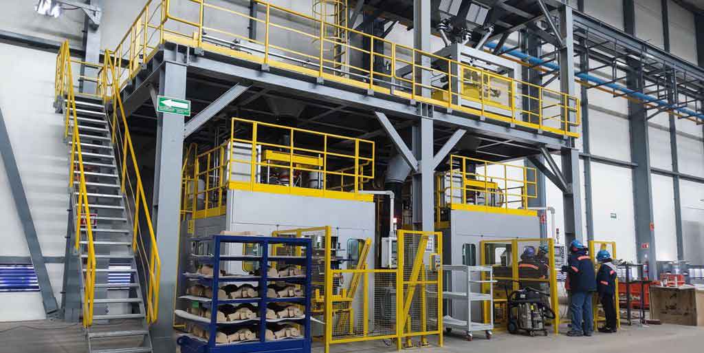
Equipment modifications were necessary to switch processes: cleaning the sand reclamation system, removing the furan resin sand reclaimer, and installing a new alkaline phenolic resin sand reclamation system comprising crushing, screening, attrition, dust collection, and cooling stages. The 20-ton continuous sand mixer was modified by connecting the reclaimed sand line to the alkaline phenolic resin sand silo, adding a new sand line, and thoroughly cleaning the resin and hardener tanks before charging with new materials.
5.1.1 Full New Sand Trial
The trial materials included silica sand, chromite sand, alkaline phenolic resin (Sinoset9210), organic ester hardener (SinoDur930), and alcohol-based zircon flour coating (HA112). Key material specifications are given in Tables 8-10.
Table 8: Silica Sand Requirements
| Parameter | 40/70 mesh retained (%) | SiO₂ (%) | Clay content (%) | Moisture (%) | Acid demand (ml) | LOI (%) | Angularity factor | Fine sand (%) | Micro fines (%) |
|---|---|---|---|---|---|---|---|---|---|
| Value | ≥85 | ≥97 | ≤0.5 | ≤0.2 | 0-5 | ≤0.5 | <1.5 | ≤0.5 | ≤0.1 |
Table 9: Chromite Sand Requirements
| Parameter | 40/100 mesh retained (%) | Cr₂O₃ (%) | SiO₂ (%) | CaO (%) | Fe₂O₃ (%) | Acid demand (ml) | Refractoriness (°C) | Micro fines (%) |
|---|---|---|---|---|---|---|---|---|
| Value | ≥85 | ≥45 | ≤0.5 | ≤0.2 | ≤25 | ≤5 | >1800 | ≤1.0 |
Table 10: Alkaline Phenolic Resin Requirements
| Parameter | Density (g·cm⁻³) | Viscosity (mPa·s) | Tensile strength (MPa, 1.7% resin addition) | ||
|---|---|---|---|---|---|
| Value | 1.20-1.25 | 50-150 | 1h ≥0.12 | 4h ≥0.3 | 24h ≥0.4 |
The process parameters for the full new sand trial: mold sand with 1.60% resin and 23% hardener (based on resin); core sand with 1.70% resin and 24% hardener; embedded chromite sand blocks with 1.50% resin and 23% hardener. Stripping occurred 50 minutes after molding, achieving 24-hour strength of 0.5-0.6 MPa. The alcohol-based zircon coating was applied 24 hours later, flame-ignited and oven-dried. Stripping performance was excellent with no sand adhesion or tearing.
Pouring was performed at 1585°C with approximately 30 seconds per mold. Compared to furan resin sand which produced dense black smoke and strong pungent odors during pouring, the alkaline phenolic resin sand produced minimal smoke initially, with a small amount of white vapor appearing about 20 minutes after pouring. Analysis showed the smoke from alkaline phenolic resin is primarily CO₂ and water vapor—nontoxic and environmentally benign—whereas furan resin sand releases H₂S and SO₂.
After shakeout and shot blasting, the castings exhibited good surface finish, dimensional accuracy within tolerance, no burn-on, and no visually detectable external cracks. However, open cracks approximately 10 mm deep were found at riser roots, and significant sand inclusion was present on as-cast surfaces. The sand adjacent to the casting burned out well and had good collapsibility; however, sand not in contact with the casting underwent secondary curing, becoming quite hard and difficult to break, increasing cleaning and reclamation difficulties.
Fluorescent magnetic particle inspection revealed approximately 30 cracks per casting on average, with the longest crack about 50 mm and depths up to 10 mm. External surface cracks appeared at a frequency of 50% (typically 2 cracks, 6 mm length, 2 mm depth). The No.1 core area showed cracks at chill joints or behind chills, with lengths of 20-50 mm and depths of 5-10 mm, appearing in 90% of castings. The No.2 core area exhibited the most cracks—10-16 per casting—concentrated beneath risers and at the small fillets where reinforcing ribs intersect flat surfaces, with lengths of 20-50 mm and depths of 3-8 mm, appearing in virtually all castings.
After rough machining, sand inclusion remained essentially unchanged—scattered inclusions on machined surfaces appeared in 100% of castings, predominantly on internal surfaces and end faces. However, internal machined surfaces showed dramatically fewer magnetic particle indications: only occasional 1-2 cracks of about 5 mm length in the internal bore, and riser-root-related indications on end faces, affecting only about 10% of castings. By comparison, furan resin sand production exhibited 10+ microcracks on virtually every machined surface.
5.1.2 25% New Sand + 75% Reclaimed Sand Trial
To evaluate cost reduction potential, a facing sand + backing sand approach was tested. For the facing sand (25 mm layer adjacent to the casting), 100% new sand was used, while the backing sand used reclaimed sand from the alkaline phenolic system. The reclaimed sand parameters are listed in Table 11.
Table 11: Alkaline Phenolic Reclaimed Sand Requirements
| Parameter | LOI (%) | Fine sand (%) | Micro fines (%) | Strength | Chromite + Cerabeads | Usage temperature |
|---|---|---|---|---|---|---|
| Value | ≤2.5 | ≤1.5 | ≤0.5 | ≥0.4 MPa (1.6% resin) | ≤10% | ≤35°C |
The resin addition for reclaimed sand was 1.50%-1.55% with hardener at 20%-25% of resin. Eight molds were poured per trial scheme. The quality of castings produced from the reclaimed sand blend was essentially equivalent to that of full new sand castings. Therefore, the 25% new + 75% reclaimed sand scheme was adopted for cost reasons.
Table 12: Crack Statistics Comparison Between Furan and Alkaline Phenolic Resin Sand
| Process | Stage | Location | Number of Cracks | Casting Occurrence (%) |
|---|---|---|---|---|
| Alkaline phenolic resin sand | Magnetic particle inspection (as-cast) | External surface | 3-8 | 50 |
| No.1 core region | 6-10 | 90 | ||
| No.2 core region | 10-16 | 100 | ||
| Machined surface inspection | No.1 core region | 1-2 | 10 | |
| Furan resin sand | Magnetic particle inspection (as-cast) | External surface | 10-15 | 100 |
| No.1 core region | 15-20 | 100 | ||
| No.2 core region | 30 | 100 | ||
| Machined surface inspection | No.1 core region | 5-12 | 100 |
These trials conclusively demonstrated the applicability of alkaline phenolic resin sand for steel casting motor shell production, achieving a 60% reduction in total crack count. Sand inclusion, however, remained unchanged, requiring resolution through process design improvements.
5.2 Casting Structure Optimization
After switching to alkaline phenolic resin sand, cracks at the No.2 core fillets remained problematic. The casting structure itself contributed significantly—the fillets where the internal cylinder surface meets horizontal faces and at semicircular arch roots had R6.35 mm radii, too small to accommodate the stress concentration. Analysis of product assembly confirmed that increasing the fillet radius to R25.4 mm would not affect assembly or performance. The modification was approved by the design engineers. Larger casting fillets facilitate casting practice and reduce crack initiation tendency.
5.3 Casting Process Scheme Optimization
5.3.1 Gating System Redesign
The original top-pour gating system was redesigned to a bottom-pour system, as illustrated. A ceramic pouring cup, an 80 mm diameter ceramic sprue, and a cross-shaped runner composed of cerabeads with ceramic inserts were used.
The bottom-pour system offers several critical advantages: (1) the cross-shaped runner effectively distributes heat, preventing localized overheating at the ingate area that would otherwise create steep thermal gradients and cause tensile-type hot tears; (2) during solidification shrinkage, the cross-shaped runner acts as four tie-bars restraining the cylindrical portion, minimizing ovality and distortion; (3) ceramic components in the runner system prevent sand erosion and subsequent sand inclusion defects; (4) smooth, quiescent mold filling allows inclusions, sand particles, and gases to float up into the risers, significantly reducing sand inclusion, gas porosity, and slag entrapment.
5.3.2 Riser Design Analysis
Shrinkage and hot tear defects at the column tops were attributed to the original ingate location creating a large hot spot combined with undersized, low-efficiency risers. The risers were redesigned from ordinary exothermic to high-efficiency insulating-exothermic type, with diameter increased from 100 mm to 110 mm at constant height. This improved the feeding efficiency and eliminated shrinkage-related defects at this location.
5.3.3 Core and Mold Optimization
The motor shell uses 14 cores. The No.1 core originally used four tile-shaped chills on its outer circumference. Although effective for achieving density, the excessive chilling power of these chills generated cracks at their edges while areas between chills remained insufficiently dense. Chromite sand has a refractoriness exceeding 1900°C and thermal conductivity several times higher than silica sand, while being less severe than steel chills. Therefore, a 30 mm thick layer of pre-embedded chromite sand around the core circumference replaced the metal chills, providing adequate chilling without cracking.
The No.2 core originally contained no chills near the riser location. However, a 60 mm thick reinforcing rib combined with the overhead riser created a considerable hot spot. During solidification, this region froze late, its liquid steel feeding adjacent earlier-solidifying areas, while simultaneously being subjected to tensile stresses from contraction of surrounding sections and the riser. The stresses concentrated severely, exceeding the alloy’s fracture strength, producing open cracks 10-20 mm deep. Seven contoured chills were added to the No.2 core to address this problem.
The No.7 core originally used round steel chills at fillet locations. The round chills did not match the fillet curvature, preventing adequate sand compaction at the chill edges. This produced weak, erosion-prone sand resulting in flash and sand inclusion on the casting. The round chills were replaced with contoured chills matching the fillet radius, allowing proper compaction and eliminating the erosion source.
In the drag mold, the two chills originally placed on the column bosses were 80 mm thick and 70 mm wide, extending the full column length. Their excessive chilling caused edge cracks and center shrinkage in the column. By reducing the chill height to half the column height and using chromite sand chilling for the upper half, near-directional solidification was achieved, resolving both crack and shrinkage defects.
5.3.4 Pouring Process Optimization
The pouring process was optimized with the following requirements: pre-pour verification of steel chemistry; minimum 5 minutes of steel settling time in the ladle; pouring temperature of 1550-1565°C (reduced from 1580-1590°C); pouring time of 25-30 seconds per mold; nozzle-to-cup distance of 200-300 mm; nozzle diameter increased from 40 mm to 60 mm; adherence to a slow-fast-slow pouring discipline with gradual stream shut-off; three supplemental feeds approximately 10 seconds after pouring completion, with the first feed at low flow rate and extended duration; tensile test bars cast before the 7th mold; maximum of 12-13 molds per heat with total net weight of 8.5-9.2 tons; immediate cleaning of frozen steel from nozzle; and mandatory ladle probe inspection if the weighing system failed. These measures ensured appropriate mold-filling velocity and minimized sand erosion.
5.4 Chemical Composition Optimization
Based on the influence of alloying elements on crack resistance, the target chemistry was optimized. The carbon content was set at 0.20%-0.25%, where crack resistance peaks. Silicon was controlled at 0.25%-0.45% to maximize crack resistance within the specification limit. Manganese was targeted at 0.60%-0.68%, providing optimal crack resistance while meeting the Mn≤0.70% requirement. Phosphorus was limited to ≤0.020% to reduce cold brittleness tendency while acknowledging practical limitations. Sulfur was the most critical element—it was statistically correlated with crack count, as shown in Table 13.
Table 13: Relationship Between Sulfur Content and Number of Cracks
| Heat No. | Sulfur Content (%) | Number of Cracks | Notes |
|---|---|---|---|
| 001 | 0.035 | 62-80 | 12 pieces |
| 002 | 0.025 | 50-58 | 12 pieces |
| 003 | 0.032 | 55-62 | 12 pieces |
| 004 | 0.020 | 47-54 | 12 pieces |
| 005 | 0.018 | 45-52 | 12 pieces |
| 006 | 0.015 | 30-45 | 12 pieces |
| 007 | 0.012 | 29-45 | 12 pieces |
| 008 | 0.028 | 53-60 | 12 pieces |
| 009 | 0.019 | 46-54 | 12 pieces |
| 010 | 0.015 | 35-43 | 12 pieces |
| 011 | 0.009 | 30-41 | 12 pieces |
| 012 | 0.030 | 60-75 | 12 pieces |
| 013 | 0.014 | 33-46 | 12 pieces |
| 014 | 0.034 | 61-76 | 12 pieces |
| 015 | 0.023 | 49-55 | 12 pieces |
| 016 | 0.008 | 30-39 | 10 pieces |
| 017 | 0.018 | 45-53 | 10 pieces |
Considering the HX-5T basic electric arc furnace capabilities, raw material constraints (especially sulfur-bearing scrap, lime, and ferroalloys), and cost factors, the sulfur content was targeted at ≤0.015%. The optimized chemical composition is shown in Table 14.
Table 14: Optimized Chemical Composition
| Element | C% | Si% | Mn% | P% | S% | Cu% |
|---|---|---|---|---|---|---|
| Range | 0.20-0.25 | 0.25-0.45 | 0.60-0.68 | ≤0.020 | ≤0.015 | ≤0.30 |
To achieve the target composition, the melting process was revised: raw materials (scrap, ferroalloys, iron ore, fluxes) must meet technical specifications with accurate weighing; carbon content after melt-down must be ≥0.70%; oxygen lancing (0.5-1.0 MPa) during melting with proper slag practice ensures early phosphorus removal; oxidation period uses ore and oxygen for decarburization with controlled rate of 0.01%-0.03% per minute; a “clean boil” period of at least 10 minutes; pre-deoxidation with silicon-manganese when carbon reaches 0.10%-0.20%, ensuring manganese ≥0.20%; after removing oxidizing slag, a reducing white slag is formed using lime:fluorspar:refractory brick = 4:1.5:0.2, with 3 kg/ton aluminum pre-deoxidation and 5-8 kg/ton silicon carbide for slag reduction; final deoxidation with 0.5 kg/ton aluminum inserted into the furnace plus 20-30 meters of aluminum wire fed into the ladle; and tapping at 1590-1620°C with a basicity ≥2.5, FeO 15%-25%, and refining time ≥15 minutes.
6. Production Practice and Results
The optimized processes were fully implemented from April through December 2016, with 2,800 steel casting motor shells produced. The overall product quality improved dramatically.
6.1 Quality Improvement
Crack reduction: Before optimization, the average crack count per casting was approximately 60 (10 external, 15 at No.1 core, 32 at No.2 core, 10 on machined surfaces). After optimization, the average count dropped to approximately 10 (1 external, 3 at No.1 core, 5 at No.2 core, 1 on machined surface). No open cracks remained; the shallowest indication was 1.5 mm and deepest was 5 mm, compared with 3-15 mm before optimization.
Table 15: Crack Count Comparison Before and After Improvement
| Location | Before (average) | After (average) |
|---|---|---|
| External surface | 10 | 1 |
| No.1 core region | 15 | 3 |
| No.2 core region | 32 | 5 |
| Machined surface | 10 | 1 |
| Total | ≈67 | ≈10 |
Sand inclusion reduction: Before optimization, the average count was approximately 80 scattered points per casting (27 external, 30 at No.1 core, 15 at No.2 core, 8 on riser end faces). After optimization, the average count was approximately 20 points (5 external, 3 at No.1 core, 5 at No.2 core, 2 on end faces), with maximum diameter not exceeding 3 mm.
Table 16: Sand Inclusion Number Comparison Before and After
| Location | Before (average) | After (average) |
|---|---|---|
| External surface | 27 | 5 |
| No.1 core region | 30 | 3 |
| No.2 core region | 15 | 5 |
| Riser end face | 8 | 2 |
| Total | ≈80 | ≈15-20 |
6.2 Scrap Rate
Before optimization, 200 pieces were produced with 38 scrapped, for a rejection rate of 19% (15% from cracks, 4% from sand inclusion). After optimization, 2,800 pieces were produced with 31 scrapped, for a rejection rate of 1.1% (0.5% from cracks, 0.25% from sand inclusion, 0.18% from misruns, 0.29% from other causes). The rejection rate decreased by nearly 18%, saving more than 3 million RMB in scrap losses.
Table 17: Rejection Rate Comparison
| Period | Production Quantity | Scrap Quantity | Rejection Rate (%) |
|---|---|---|---|
| Before optimization | 200 | 38 | 19.0 |
| After optimization | 2800 | 31 | 1.1 |
6.3 Work-in-Process and Delivery Performance
The old process created backlogs at welding repair and machining stages due to high defect rates. Each stage had approximately 150 pieces of work-in-process inventory. After implementing the new process, work-in-process reduced to 10 pieces per stage, doubling overall production efficiency. Monthly output increased from 160 to 450 finished pieces, and from June through December 2016, not a single delivery deadline was missed. Improved quality and on-time delivery established a solid foundation for securing the motor shell market.
6.4 Quality Safety Risk and Customer Feedback
Steel casting products inevitably contain some defects. Since the motor shell is supplied as a rough casting and approximately half of the internal and external surfaces are machined by the customer, exposed defects pose significant quality risk. During January-March 2016, among 160 units supplied, 10 were returned due to exposed cracks or sand inclusion on machined surfaces. One unit was scrapped by the customer after assembly due to a severe crack discovered during final machining, causing a 100,000 RMB loss. More seriously, undetected internal defects could cause in-service failures with potentially catastrophic safety consequences.
After process optimization, from April to December 2016, among 2,760 units supplied, 37 were returned for exposed defects—all repairable and none scrapped. The customer feedback rate dropped from 6.25% to 1.34%, comfortably below the 2% target.
Table 18: Customer Quality Feedback Rate Comparison
| Period | Pieces Supplied | Feedback Pieces | Feedback Rate (%) |
|---|---|---|---|
| Before optimization | 160 | 10 | 6.25 |
| After optimization | 2760 | 37 | 1.34 |
6.5 Cost Analysis
6.5.1 Molding Material Cost
For furan resin sand, the average resin addition was 0.9% with hardener at 35% of resin. Resin price was 20,000 RMB/ton, hardener 5,500 RMB/ton. For 1 ton of castings with sand-to-iron ratio of 4:1 and 90% sand recovery, the calculation per ton of castings is:
New sand: 1000 kg × 10% × 4 = 400 kg → 400 × 0.4 = 160 RMB (sand at 0.4 RMB/kg)
Reclaimed sand: 1000 kg × 90% × 4 = 3,600 kg → 3,600 × 0.15 = 540 RMB (reclaimed sand at 0.15 RMB/kg)
Resin: 4,000 × 0.9% = 36 kg → 36 × 20 = 720 RMB
Hardener: 36 × 35% = 12.6 kg → 12.6 × 5.5 = 69 RMB
Total = 160 + 540 + 720 + 69 = 1,489 RMB per ton of castings
For alkaline phenolic resin sand, the average resin addition was 1.6% with hardener at 23% of resin. Resin price was 9,000 RMB/ton, hardener 16,000 RMB/ton. With 25% new + 75% reclaimed sand, the calculation per ton of castings is:
New sand: 4,000 × 25% = 1,000 kg → 1,000 × 0.4 = 400 RMB
Reclaimed sand: 4,000 × 75% = 3,000 kg → 3,000 × 0.18 = 540 RMB
Resin: 4,000 × 1.6% = 64 kg → 64 × 9 = 576 RMB
Hardener: 64 × 23% = 14.72 kg → 14.72 × 16 = 236 RMB
Total = 400 + 540 + 576 + 236 = 1,752 RMB per ton of castings
Table 19: Molding Material Cost Comparison (per ton of castings)
| Item | Alkaline Phenolic (RMB) | Furan Resin (RMB) | Difference (RMB) |
|---|---|---|---|
| Resin + hardener | 812 | 789 | 23 |
| Sand (new + reclaimed) | 940 | 700 | 240 |
| Total | 1,752 | 1,489 | 263 |
Thus, the alkaline phenolic resin sand process costs 263 RMB more per ton of castings in molding materials, primarily due to the higher proportion of new sand required.
6.5.2 Welding Repair Cost
Improved casting quality dramatically reduced welding repair work. The average repair cost per piece dropped from 486 RMB to 260 RMB, a saving of 226 RMB per piece.
Table 20: Average Welding Repair Cost per Motor Shell
| Item | Consumables (RMB) | Grinding Tools (RMB) | Labor (RMB) | Other (RMB) | Total (RMB) |
|---|---|---|---|---|---|
| Before optimization | 25 | 21 | 380 | 60 | 486 |
| After optimization | 5 | 4 | 200 | 51 | 260 |
| Difference | 20 | 17 | 180 | 9 | 226 |
6.5.3 Quality Loss Cost
Before optimization: production of 200 pieces had scrap losses of 210,000 RMB; customer compensation on 160 supplied pieces was 110,000 RMB. Total quality loss of 320,000 RMB translates to 2,000 RMB per piece.
After optimization: production of 2,800 pieces had scrap losses of 220,000 RMB; customer compensation on 2,760 supplied pieces was 25,000 RMB. Total quality loss of 245,000 RMB translates to 88 RMB per piece.
Table 21: Quality Loss Cost per Piece
| Period | Production Scrap Loss (RMB) | Customer Compensation (RMB) | Total Loss (RMB) | Per-Piece Loss (RMB) |
|---|---|---|---|---|
| Before optimization | 210,000 | 110,000 | 320,000 | 2,000 |
| After optimization | 220,000 | 25,000 | 245,000 | 88 |
7. Conclusions and Future Work
7.1 Conclusions
This thesis addressed the defects and process deficiencies in the production of steel casting motor shells using the furan resin sand process, the original casting design, and steel melting practice. Through a comprehensive investigation of international and domestic molding processes, casting technologies, and melting/pouring practices, the root causes of hot tears and sand inclusion were identified and systematic countermeasures were developed and implemented. The principal research findings are summarized below:
- Molding sand process optimization: Replacing furan resin sand with alkaline phenolic resin sand significantly reduced the crack count in steel casting motor shells. A 60% reduction in total cracks was achieved. The process parameters—resin addition of 1.5%-1.8%, hardener at 20%-25% of resin, stripping strength of 0.25-0.30 MPa, and 24-hour strength of 0.3-0.7 MPa—provide adequate mold performance while delivering superior high-temperature collapsibility. The 25% new + 75% reclaimed sand scheme was adopted for economic viability without compromising quality.
- Casting structure optimization: Increasing the fillet radii at internal reinforcing ribs from R6.35 mm to R25.4 mm (after verifying design acceptability) eliminated stress concentration-induced cracking at these locations.
- Casting process optimization: The bottom-pour gating system with ceramic lined runners and sprue eliminated sand erosion and improved inclusion flotation. High-efficiency insulating-exothermic risers with enlarged diameter improved feeding. The No.1 core replaced metal chills with chromite sand pre-embedded layer, eliminating chill-edge cracks. The No.2 core received seven contoured chills to eliminate hot spot cracking. The No.7 core’s round chills were replaced with contoured chills. The drag mold’s column chills were shortened with chromite sand chilling in the upper section to achieve directional solidification. Optimized pouring parameters—temperature 1550-1565°C, time 25-30 seconds, nozzle diameter 60 mm, and controlled pouring discipline—reduced both crack and sand inclusion tendency.
- Chemical composition optimization: Target composition of 0.20%-0.25% C, 0.25%-0.45% Si, 0.60%-0.68% Mn, P≤0.020%, and S≤0.015% maximizes alloy crack resistance. Implementation through controlled melting practice including proper oxidation, white slag refining, and final deoxidation achieved these targets consistently.
The production practice from April through December 2016 demonstrated outstanding results: crack count reduced from 67 to 10 per casting, sand inclusion points reduced from 80 to 20, rejection rate reduced from 19% to 1.1%, and customer feedback rate reduced from 6.25% to 1.34%. Despite a modest 263 RMB/ton increase in molding material cost, the welding repair cost saving of 226 RMB per piece and the quality loss cost saving of 1,912 RMB per piece resulted in substantial net cost reduction. On-time delivery improved from 160 to 450 pieces per month with no delivery delays.
7.2 Future Work
While the optimized processes dramatically improved the quality of steel casting motor shells, several challenges remain for continued improvement:
- Alkaline phenolic resin sand reclamation remains suboptimal—the recovery rate and reclaimed sand quality are not fully satisfactory, leading to higher production costs. Further research into improved reclamation technologies is needed.
- The optimized process significantly reduced but did not completely eliminate cracks and sand inclusion. For a product where “zero defects” is the ultimate goal, continued process refinement—including computer simulation of mold filling and solidification, advanced sensor-based process monitoring, and further optimization of gating and feeding systems—is warranted.
- The interaction between alkaline phenolic resin sand and various specialty sands (chromite, cerabeads) deserves systematic investigation to optimize chilling strategies for complex hot spots in thin-walled steel casting applications.
In summary, this research project successfully resolved the hot tear and sand inclusion problems in steel casting motor shell production, achieving significant improvements in quality, cost, delivery, and safety. The findings and methodologies developed herein provide valuable practical guidance and reference for the production of similar steel casting components.