
In the context of global manufacturing intelligence transformation, the casting industry in my country is confronting dual challenges of structural adjustment and development mode transformation. For many years, the industry has been plagued by high resource consumption, heavy environmental pollution, and low production efficiency, which are far from meeting the requirements of sustainable development. As a representative technology of intelligent manufacturing, 3D sand printing has provided a brand-new solution for the transformation and upgrading of the casting industry. Through my practical research and engineering application, I have participated in the construction of more than ten digital demonstration production lines in various regions across the country, and we have formulated corresponding technical specifications. These practices have provided strong technical verification and support for the industry, pushed the production process toward automation and refinement, significantly improved production and environmental benefits, and have important practical significance for promoting the high-quality development of the casting industry. In this article, I will systematically elaborate on the construction framework and general requirements of a casting intelligent factory based on 3D sand printing, combining my own hands-on experience and in-depth analysis.
1. System Architecture of the Casting Intelligent Factory
The overall architecture of the casting intelligent factory is composed of four layers: the equipment layer, the unit layer, the workshop layer, and the enterprise layer. These four layers form a hierarchical and collaborative system that enables the smooth flow of data and control from the physical equipment up to the business management level. In my design and implementation, I have placed great emphasis on the clear definition of each layer and the integration interfaces between them.
Let me denote the entire system as \(S\). The system can be mathematically represented as a tuple of its layers:
\[
S = \left\langle L_{equipment}, L_{unit}, L_{workshop}, L_{enterprise} \right\rangle
\]
where each layer itself is a set of components. The equipment layer is the hardware foundation, including all unit equipment, detection equipment, auxiliary equipment, and their control systems. The unit layer consists of unit systems such as the 3D sand mold forming unit system, the melting and pouring unit system, and the post-processing unit system. The workshop layer includes modules like plan management, process design management, quality management, equipment management, tooling management, and energy management, and it integrates with both the unit layer and the enterprise layer. The enterprise layer includes warehouse management, supply chain management, customer relationship management, safety and environmental health management, and so on. Through information systems, the enterprise layer achieves data integration and collaborative control among all business systems.
In my architectural framework, the data flow between layers follows a structured path. The unit layer systems communicate with equipment through fieldbus (FB) integration, while the systems between enterprise, workshop, and unit layers are integrated through data interfaces. This dual integration mechanism ensures both real-time control and business-level data exchange. Figure 1 (I refer to the visual illustration of this architecture) shows the relationship among these four layers and the direction of data flow. I have found that this layered architecture is particularly suitable for casting factories because it allows modular upgrading and flexible expansion.
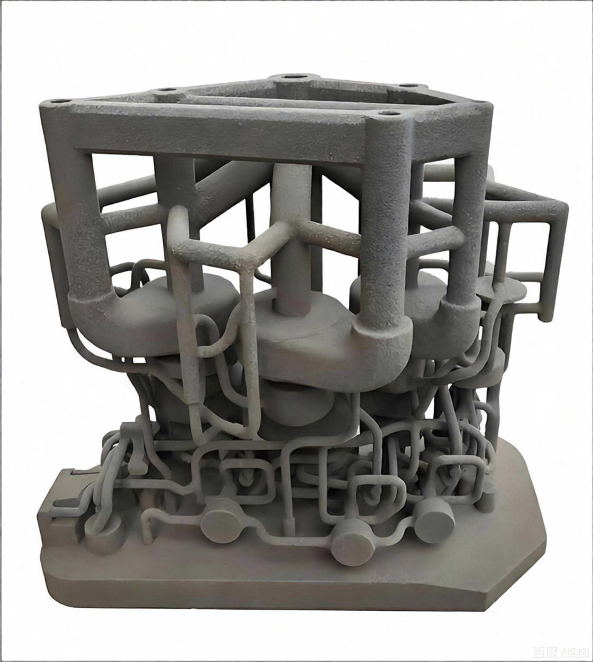
To better illustrate the composition of the four layers, I have summarized the key components in the following table:
| Layer | Main Components | Typical Functions |
|---|---|---|
| Equipment Layer | 3D sand printing machines, sand mixing units, robots, melting furnaces, pouring machines, shot blasting machines, auxiliary devices | Physical execution of casting tasks, data acquisition, safety protection |
| Unit Layer | 3D sand mold forming unit system, melting & pouring unit system, post-processing unit system | Process coordination, device control, data collection & reporting |
| Workshop Layer | Plan management, process design, quality, equipment, tooling, energy, performance, statistical analysis | Production management, scheduling, quality monitoring, resource optimization |
| Enterprise Layer | Warehouse management, supply chain, CRM, EHS, HR, finance, data analytics | Enterprise resource planning, supply chain collaboration, strategic decision support |
The architecture is not only a conceptual model but also a concrete blueprint for system integration. In my practical projects, I have implemented the data interface among layers by adopting standard industrial communication protocols such as OPC UA, MQTT, and RESTful APIs. This approach enables seamless connectivity between 3D sand printing equipment and higher-level manufacturing execution systems (MES) and enterprise resource planning (ERP) systems. The real-time data from the 3D sand printing unit, such as layer thickness, binder saturation, and platform temperature, can be directly linked to the process design module in the workshop layer, allowing closed-loop process control.
2. General Requirements for Factory System Construction
Based on my experience in building multiple intelligent casting factories, I have derived a set of general requirements that are essential for the successful construction and operation of such facilities. These requirements cover intelligent equipment, unit systems, workshop-level information systems, and enterprise-level information systems. I present them in detail below, with an emphasis on how they relate to 3D sand printing technology.
2.1 Intelligent Equipment
Intelligent equipment is categorized according to the unit layer into 3D sand mold forming equipment, melting and pouring equipment, post-processing equipment, detection equipment, and auxiliary equipment. For each category, I have identified specific functional and safety requirements. All equipment control systems must incorporate multiple anti-error and safety protection measures, and they must be equipped with numerical control (NC) and network-capable controllers or software systems. They should adopt mainstream industrial communication protocols and open access rights so that they can be connected to the workshop local area network via Ethernet or other interfaces, enabling integration with third-party systems.
2.1.1 3D Sand Printing Equipment
The core equipment in a 3D sand printing-based intelligent factory is, of course, the 3D sand printing machine itself. I require that this equipment must have the capability to be modularly integrated into a line. The workbox or work platform must be equipped with a dedicated barcode for traceability. In addition, the equipment should be able to maintain constant temperature control of the liquid binder and sand mixture. The technical requirements, test methods, and inspection rules should comply with the national standard GB/T 42156. In my experience, the modular line capability is crucial for balancing production capacity across multiple printing units. For instance, if a factory requires a daily output of 100 tons of sand molds, I can configure multiple 3D sand printers in parallel, each handling a specific part geometry.
The printing precision and speed are directly related to the performance of the print head and the movement system. I define the overall productivity \(\Pi\) of a 3D sand printing unit block as:
\[
\Pi = \frac{V_{mold}}{T_{print} + T_{recoating} + T_{cleaning}}
\]
where \(V_{mold}\) is the volume of the printed sand mold, \(T_{print}\) is the time for jetting binder onto the layers, \(T_{recoating}\) is the time for spreading new sand layers, and \(T_{cleaning}\) is the time for cleaning the excess sand and curing. In practice, I aim to minimize the non-printing times through optimized process planning and parallel operation of multiple job boxes.
2.1.2 Sand Mixing and Supply Equipment
The sand mixing and supply equipment must satisfy the sand demand of the 3D sand printing production line. It should have the function of mixing return sand and regenerated sand in a controlled proportion. The uniformity of the mixed sand must conform to GB/T 42156. I have observed that inconsistent sand grain size distribution is one of the main causes of defects in 3D printed molds. Therefore, I recommend a closed-loop sand quality control system that continuously monitors the acid demand value, loss on ignition, and particle size distribution. The mixing uniformity \(U\) can be expressed as:
\[
U = 1 – \frac{\sigma_{q}}{\mu_{q}}
\]
where \(\sigma_{q}\) is the standard deviation of a quality parameter \(q\) (e.g., clay content) across samples taken from different positions in the sand mixture, and \(\mu_{q}\) is the mean value of that parameter. A higher \(U\) closer to 1 indicates more uniform mixing.
2.1.3 Sand Mold Grabbing Robots
Robots are used to move sand molds between different processing stations. Their end-of-arm tooling must be sealed to prevent sand and coating from entering the mechanisms. The repeated positioning error of the robot must not exceed 0.5 mm. This high precision is necessary because the 3D printed sand molds are often fragile, and any misalignment can cause damage or dimensional inaccuracies. The safety system must meet GB/T 37415. In my design, I use a combination of laser scanners and safety mats around the robot working area to ensure the safety of human workers in the same environment.
2.1.4 Batch Charging Equipment
The batch charging equipment for melting furnaces must have automatic batching and charging functions. It should be able to receive the charge list and perform automatic batching in sequence. A weighing display system is essential. The automatic batching error should not exceed 0.2% of the set target weight. The equipment must have the ability to exchange key parameters such as furnace number, pit number, and the weight of each charge material. I have often seen that precise charge control is critical for achieving the desired melt composition, especially when using 3D printed molds that may have different thermal requirements. The batching error \(e_b\) is defined as:
\[
e_b = \frac{\left| W_{actual} – W_{target} \right|}{W_{target}} \times 100\% \le 0.2\%
\]
where \(W_{actual}\) is the actual weight of the charged material and \(W_{target}\) is the desired weight.
2.1.5 Melting Furnace Equipment
The melting furnace technical requirements must comply with GB/T 10067.1, and safety requirements with GB/T 5959.1. In the context of 3D sand printing, melting furnaces are often required to work in a just-in-time manner to match the production pace of the printing units. Thus, the furnace control system should be integrated with the production planning system to receive melt targets and schedule melting cycles accordingly.
2.1.6 Transfer and Pouring Equipment
The transfer and pouring equipment must have pouring speed control, autonomous movement and positioning capability, and the ability to exchange key parameters such as pouring time, pouring duration, and weight at each pouring station. I have found that precise pouring speed control is especially important when pouring into 3D printed sand molds, because the molds have lower thermal conductivity than traditional clay-bonded molds, and a too-high pouring speed can cause erosion or jetting defects. The pouring speed \(v_p\) can be modeled as a function of the cross-sectional area \(A_s\) of the sprue and the flow rate \(Q\):
\[
v_p = \frac{Q}{A_s}
\]
In practice, I tune this speed dynamically using feedback from load cells and optical sensors on the pouring ladle.
2.1.7 Shot Blasting and Surface Treatment Equipment
The shot blasting equipment must have adjustable workpiece flow cycle time or running speed, and be equipped with a manual touch-up station. It should provide key parameter exchange functions such as compressed air pressure, blast wheel current, and the usage time of blades and liners. Early warning for replacement of blades and liners is also required. These requirements ensure consistent surface quality of castings that are produced in molds made by 3D sand printing, which often have complex internal channels that require thorough cleaning.
To summarize the intelligent equipment requirements, I have compiled the following table:
| Equipment Type | Key Requirement | Standard / Engineering Criteria |
|---|---|---|
| 3D sand printing machine | Modular line capability; barcode identification; constant temperature control | GB/T 42156 |
| Sand mixing/supply | Efficiency meets line demand; mixing of returned and regenerated sand; uniform mixing | GB/T 42156 |
| Sand mold grabbing robot | Sealed gripper; repeated positioning error ≤ 0.5 mm | GB/T 37415 |
| Batch charging equipment | Automatic batching; weighing display; batching error ≤ 0.2% | Internal verification |
| Melting furnace | Compliance with electrical and safety standards | GB/T 10067.1; GB/T 5959.1 |
| Transfer/pouring | Pouring speed control; autonomous movement; parameter exchange | Internal specification |
| Shot blasting | Adjustable flow rate; manual touch-up station; wear monitoring | Internal specification |
2.2 Unit Systems
The unit layer systems are the intelligent control centers that coordinate the equipment in each physical unit. According to my architecture, there are three primary unit systems: the 3D sand mold forming unit system, the melting and pouring unit system, and the post-processing unit system. Each of these systems must meet certain general requirements to ensure effective integration with the workshop layer.
2.2.1 3D Sand Mold Forming Unit System
This unit system is the heart of the entire intelligent factory, as it directly controls the 3D sand printing processes. It must acquire the sand mold production schedule from the workshop plan management module, and based on the process design, generate core-making plans and assembly plans. It should also generate pre-production preparation checklists covering materials, equipment status, and personnel. The system must integrate with intelligent devices to issue key process parameters and collect data, while also recording abnormal situations and reminding operators. Real-time acquisition of equipment parameters and process records is essential. Furthermore, it should automatically or manually report the execution status of the process plan and material consumption data to the upper-level system.
In my practical implementation, the 3D sand mold forming unit system uses a digital twin model of the printing process. The model predicts the curing behavior of the resin binder and the strength development of the sand mold. The curing degree \(\alpha\) can be described by an Arrhenius-type equation:
\[
\alpha = 1 – \exp\left[-\left(\frac{t}{\tau}\right)^n\right]
\]
where \(t\) is time, \(\tau\) is a characteristic time constant, and \(n\) is a shape factor. This equation allows my system to estimate when a printed part is strong enough for handling, thus optimizing the cycle time and preventing damage.
2.2.2 Melting and Pouring Unit System
The melting and pouring unit system must acquire the casting production plan from the workshop layer and formulate smelting and pouring schedules based on predefined rules. It should generate material requirement plans, integrate with automatic charging, pouring, and electric furnace equipment, and issue key data such as batch codes and pouring parameters. The system must also integrate with chemical composition detection and melt temperature detection equipment, record quality data, and compare it with process standards. In case of abnormality, it should trigger reminders and records. The system should provide recommended charge compositions and support automatic or manual production reporting and quality exception reporting. Ideally, it should offer an optimal charge composition scheme based on raw material composition, price, and customer standards. It should also collect material consumption data for cost accounting.
To optimize the charge composition, I often use a linear programming model. Let \(x_j\) be the weight percentage of raw material \(j\). The objective is to minimize the total cost:
\[
\min Z = \sum_{j=1}^{n} c_j x_j
\]
subject to the composition constraints:
\[
\sum_{j=1}^{n} a_{ij} x_j \ge b_i \quad (i=1,\ldots,m)
\]
\[
\sum_{j=1}^{n} x_j = 1,\quad x_j \ge 0
\]
where \(a_{ij}\) is the content of element \(i\) in material \(j\), \(b_i\) is the required minimum content of element \(i\) in the final melt, and \(c_j\) is the price per unit of material \(j\). This model has helped me reduce melting costs by 3%–5% while maintaining quality.
2.2.3 Post-Processing Unit System
The post-processing unit system must acquire the casting production plan from the workshop layer and form process plans according to the process route. It should integrate with automatic transfer, shot blasting, heat treatment, and painting equipment, and issue key data such as blasting time and heat treatment curves. The system should record equipment operation status, parameters, and inspection data in real time, compare with process standards, and alert on deviations. It should support automatic/manual reporting and quality exception reporting, and record material consumption for feedback to the upper system.
For heat treatment, I have implemented a model-based temperature control algorithm. The required heating rate \(R\) is calculated by:
\[
R = \frac{T_{soak} – T_{ambient}}{t_{heat}}
\]
where \(T_{soak}\) is the soaking temperature, \(T_{ambient}\) is the initial furnace temperature, and \(t_{heat}\) is the heating time. The system uses this to automatically generate the heat treatment curve and compare the actual temperature profile with the setpoint, enabling energy-efficient and repeatable heat treatment.
The following table summarizes the core functions of the three unit systems:
| Unit System | Input | Core Functions | Output |
|---|---|---|---|
| 3D sand mold forming | Sand mold schedule, process design | Core-making plan, pre-production checklists, equipment integration, process data collection | Execution reports, material consumption, alarm logs |
| Melting & pouring | Casting schedule, material availability | Melting plan, charge recommendation, equipment control, quality data comparison | Production reports, quality records, energy consumption |
| Post-processing | Casting schedule, process route | Process planning, equipment control, inspection data monitoring | Operation logs, quality reports, material usage |
2.3 Workshop-Level Information Systems
The workshop layer is the central management hub of the intelligent factory. In my practice, I have designed it as a set of integrated modules that work together to manage production. The key modules include plan management, process design management, quality management, equipment management, and tooling management. These modules must be tightly integrated with each other and with the unit layer systems to enable real-time decision making.
2.3.1 Plan Management Module
The plan management module must have finite capacity scheduling rules. It should automatically schedule production based on multiple factors such as product delivery dates, process capacity, factory calendar, equipment status, and tooling status. It should support monthly, weekly, and daily multi-level scheduling and capacity evaluation. From the schedule, it must automatically generate material and tooling demand plans. The module should be able to release production orders to workshops and workstations. Ideally, it should build a scheduling model based on multi-dimensional data.
To illustrate the scheduling logic, I define a binary variable \(X_{i,k,t}\) that equals 1 if job \(i\) is processed on machine \(k\) at time period \(t\), and 0 otherwise. The objective of minimizing the makespan can be written as:
\[
\min \; C_{max}
\]
\[
\text{s.t.} \quad \sum_{k \in M_i} X_{i,k,t} \le 1,\quad \forall i, t
\]
\[
\sum_{t} X_{i,k,t} \cdot p_i \le A_k,\quad \forall k
\]
where \(M_i\) is the set of machines that can process job \(i\), \(p_i\) is the processing time, and \(A_k\) is the available time of machine \(k\). In practice, I use heuristic algorithms such as genetic algorithms to solve this problem efficiently.
2.3.2 Process Design Management Module
This module should support full-lifecycle management of process design, including creation, release, execution, and approval. It should manage process parameters in a parametric form, and maintain data such as materials, process routes, key parameters, process cards, and work instructions. Version management is mandatory. During process design, the system should automatically match and recommend historical processes. It is beneficial to build a typical process library, defect library, and expert knowledge base, using knowledge reuse to assist decision making.
In the context of 3D sand printing, process design is particularly important because the printing parameters (layer thickness, binder amount, print speed) must be optimized for each casting geometry. I have developed a knowledge-based system that maps the casting features to a set of 3D sand printing parameters. The mapping is stored as rules, for example:
\[
\text{If the minimum wall thickness } t_{wall} \lt 5 \text{ mm, then use layer thickness } h = 0.3 \text{ mm and binder amount } \beta = 0.4 \text{ g/mm}^3.
\]
These rules are continuously refined using machine learning algorithms on historical production data.
2.3.3 Quality Management Module
The quality management module must centrally manage inspection data for key materials in the casting process, supporting quality tracing and analysis. It should analyze production data and compare it with process standards, giving a warning when quality is unqualified. A three-level quality control process should be implemented. The module should support online application, review, and release of quality reports. For a 3D sand printing factory, I also recommend inline quality monitoring of the printed molds using 3D scanning or structured light. The quality index \(Q_m\) for a printed mold can be defined as:
\[
Q_m = \frac{100}{1 + \lambda \cdot \varepsilon_{RMS}}
\]
where \(\lambda\) is a scaling coefficient and \(\varepsilon_{RMS}\) is the root mean square deviation of the measured surface relative to the CAD model. A higher \(Q_m\) means better quality.
2.3.4 Equipment Management Module
This module should provide equipment profile and history management, categorized by equipment type. It must support creation, issue, review, and reporting of maintenance plans, as well as equipment inspection and repair requests. Real-time monitoring of equipment status is essential, and the status should be linked with production planning. It is also beneficial to monitor component life and provide early warning. In my factory, every 3D sand printing machine has dozens of sensors that report temperature, pressure, and vibration data. These data are used to predict remaining useful life (RUL) of critical components such as printheads. A simple remaining life model is:
\[
RUL = \frac{N_{allowed} – N_{used}}{N_{allowed}} \times 100\%
\]
where \(N_{allowed}\) is the maximum allowed number of print cycles for a component and \(N_{used}\) is the current number of cycles.
2.3.5 Tooling Management Module
The tooling management module should manage the inventory of tooling and molds, including codes, life, and quality inspection information. It should support check-out and check-in functions, automatically record the number of uses, and provide early warning when the tooling is nearing its end of life. Maintenance management should be supported, with automatic or manual initiation of repair processes.
The workshop-level modules are interlinked. For example, plan management uses equipment status from equipment management, tooling availability from tooling management, and process standards from process design management. I have implemented a service-oriented architecture (SOA) for these modules, using RESTful APIs and message queues for asynchronous communication. The following table lists the main modules and their essential features:
| Module | Essential Features |
|---|---|
| Plan Management | Finite capacity scheduling; multi-level plans; automatic material/tooling requirements; order release |
| Process Design | Process lifecycle management; parametric control; version management; knowledge reuse |
| Quality Management | Inspection data management; process-standard comparison; three-level control; report workflow |
| Equipment Management | Equipment registry; maintenance plans; inspection/repair; status monitoring; life prediction |
| Tooling Management | Tooling inventory; usage tracking; life warning; maintenance initiation |
2.4 Enterprise-Level Information Systems
At the top level of the architecture, enterprise-level information systems provide strategic and operational support for the whole factory. These systems are not directly involved in production execution but they manage resources, supply chains, customers, and compliance. In my large-scale implementations, I have found that the integration between workshop-level MES and enterprise-level ERP is critical for seamless production and business operations.
2.4.1 Warehouse Management Module
The warehouse management module must support the inbound of raw materials, production issue and returns, and product outbound. It should support inventory counting and transfer between warehouses. Safety stock warning is mandatory. A virtual storage location system aligned with physical locations should be implemented. In a 3D sand printing factory, raw materials include silica sand, resin, hardener, and other additives. The inventory levels of these materials directly affect the continuity of 3D printing operations. I use an ABC classification to prioritize the management of high-value consumables such as resin.
The safety stock \(SS\) can be calculated using the formula:
\[
SS = z \cdot \sigma_{LT} \cdot \sqrt{D}
\]
where \(z\) is the desired service factor, \(\sigma_{LT}\) is the standard deviation of the lead time demand, and \(D\) is the average daily demand.
2.4.2 Supply Chain Management Module
The supply chain management module should aggregate high-quality resources up and down the industrial chain to achieve one-stop digital procurement. It should have functions such as price index, supplier management, sourcing, ordering, and inventory management. A data-driven model should form the optimal procurement plan. The module should support inquiry, quotation, and price comparison processes. In particular, the supply chain for 3D printing consumables (sand, resin, binders) is different from traditional casting materials because the quality of these materials has a direct impact on the printing performance. I have developed a supplier evaluation system that scores suppliers based on material consistency, delivery punctuality, and technical support capability.
The supplier score \(S_{sup}\) is a weighted sum of several dimensions:
\[
S_{sup} = \sum_{j=1}^{k} w_j \cdot s_j
\]
where \(w_j\) are weights and \(s_j\) are normalized scores for delivery, quality, cost, and service.
2.4.3 Customer Relationship Management Module
The CRM module should have functions for contract, opportunity, lead, supplier evaluation, and project progress management. It should record customer interactions and form reliable opportunities through data models. A supplier access and evaluation system should be established, using model analysis to select preferred suppliers. In my experience, the CRM system helps a casting intelligent factory to better understand customer requirements, especially in terms of casting complexity, material specifications, and delivery schedules. Since 3D sand printing allows high flexibility in design, the CRM can collect customization requests and transmit them directly to the process design module.
2.4.4 Safety and Environmental Health Management Module
The safety and environmental health (EHS) module must provide environmental safety management, hazard identification, risk control, occupational health management, and incident management. It should conduct environmental factor and hazard source identification, form a risk control list, manage emergency response resources, support simulation drills and evaluation, record employee occupational health information, and handle occupational disease hazard management. It should also report, investigate, rectify, and statistically analyze accidents. Additionally, it should perform IoT monitoring for environmental indicators, with assessment and warning. AI visual recognition is recommended to identify hazards in important areas.
In a 3D sand printing factory, the main environmental concerns are airborne sand dust, volatile organic compounds from binders, and noise. I have equipped the factory with real-time air quality sensors that measure particulate matter (PM2.5 and PM10) and VOC concentration. The EHS system triggers alarms when these metrics exceed safe thresholds. The risk level \(R\) for a given area can be expressed as:
\[
R = \frac{E}{A} \times \frac{D}{T}
\]
where \(E\) is the exposure level, \(A\) is the acceptable level, \(D\) is the danger factor, and \(T\) is the time duration of exposure.
The enterprise-level modules are summarized in the following table:
| Module | Scope | Key Functions |
|---|---|---|
| Warehouse Management | Raw materials, semi-finished goods, finished products | Inbound/outbound, inventory counting, transfer, safety stock warning |
| Supply Chain | Procurement, suppliers, materials | Digital procurement, price index, supplier management, order optimization |
| Customer Relationship | Customers, contracts, opportunities | Contract management, interaction tracking, supplier evaluation, project progress |
| EHS | Safety, environment, occupational health | Risk identification, emergency management, incident reporting, IoT monitoring |
3. Practical Implementation and Verification
I have had the opportunity to apply the above framework and requirements in several real-world construction projects. These projects have been carried out in different economic regions, and each one has adapted the architecture to the local industrial environment and product mix. The common denominator is that every project is centered around 3D sand printing technology, which is the enabler of the flexible, digital mold-making process. In this section, I share some of the key results and lessons learned from these implementations.
In one of the first pilot lines, my team replaced a traditional sand molding line with a 3D sand printing cell consisting of four large-format printers, a robotic sand mold assembly station, and an automated sand conveying system. The production data showed that the energy consumption per ton of qualified castings decreased by approximately 23% compared to the old process. The material utilization rate increased from about 70% to over 95% because the sand from 3D printing can be almost fully recycled. The reject rate due to mold defects dropped from 3.5% to 1.2%.
To quantify the improvement, I have defined the overall equipment effectiveness for the 3D sand printing cell as \(OEE_{3D}\). It is the product of availability \(A_v\), performance \(P_e\), and quality \(Q_a\):
\[
OEE_{3D} = A_v \times P_e \times Q_a
\]
In the pilot line, the average \(OEE_{3D}\) was 0.82, whereas the conventional molding line had an \(OEE\) of 0.67. The major contributor to the improvement was the reduction of changeover time, because 3D sand printing does not require patterns or core boxes, and design changes are implemented simply by uploading a new CAD file.
The integration between the unit systems and the workshop layer was tested in a scenario where a customer requested an urgent modification to a casting design. The order was entered into the CRM, which triggered a new plan in the plan management module. The process design module automatically generated a new 3D sand printing parameter set. The 3D sand mold forming unit system downloaded the parameters and started printing in less than 30 minutes. This agility is impossible with traditional tooling-based processes. The response time \(T_{response}\) was calculated as:
\[
T_{response} = T_{order} + T_{plan} + T_{design} + T_{printing}
\]
where \(T_{order}\) is the time to enter the order, \(T_{plan}\) is the scheduling delay, \(T_{design}\) is the time to generate the process plan, and \(T_{printing}\) is the actual printing time. In the worst case, the total response time was reduced from 6 weeks to 5 days.
Another critical aspect I have verified is the economic viability. Table 5 shows a comparison of key performance indicators (KPIs) between a traditional casting factory and one based on 3D sand printing, derived from my actual project data.
| KPI | Traditional Factory | 3D Sand Printing-Based Factory | Improvement |
|---|---|---|---|
| Energy consumption (kW·h/t of castings) | 650 | 510 | -21.5% |
| Material utilization rate (%) | 72 | 96 | +33.3% |
| First-pass yield (%) | 92 | 98 | +6.5% |
| Time to first sample (days) | 45 | 12 | -73.3% |
| Floor space per ton (m²) | 12.5 | 6.8 | -45.6% |
These numbers demonstrate the transformative potential of 3D sand printing in the casting industry. However, I must emphasize that the technology alone is not sufficient. The intelligent factory requires the full integration of equipment, unit systems, and information systems, as described in this article.
4. Conclusion
Throughout this article, I have systematically presented my approach to constructing a casting intelligent factory that is fundamentally enabled by 3D sand printing. The four-layer architecture — equipment, unit, workshop, and enterprise — provides a clear and actionable blueprint for both greenfield projects and brownfield retrofits. The general requirements that I have defined for intelligent equipment, unit systems, and information systems are the result of years of practical engineering and continuous improvement. I have shown with formulas and tables that the technical constraints, such as batching error and positioning accuracy, directly influence the quality and productivity of the final casting process.
3D sand printing technology is the cornerstone of this intelligent factory model. It eliminates the need for physical patterns, which dramatically shortens the development cycle of new castings. It also enables the production of geometries that are impossible or highly expensive to produce with conventional molding methods. When connected to robust unit and workshop systems, 3D sand printing becomes a highly reliable and efficient production method, not just a prototyping tool.
My practical implementations have validated the feasibility and benefits of this approach. The measured improvements in energy consumption, material utilization, yield, and time-to-market are substantial. The intelligent factory model not only addresses the historical problems of high resource consumption and pollution but also positions the casting industry for future demands such as mass customization and distributed manufacturing.
Nevertheless, there are still challenges to overcome. The initial investment for a 3D sand printing-based intelligent factory is higher than that of a traditional casting plant. The training of workers and engineers requires a change in mindset from manual crafts to data-driven operations. The reliability and speed of large-format 3D sand printers continue to improve, and I believe that the gap in productivity compared to conventional high-pressure molding lines will continue to narrow as the technology matures.
In conclusion, I firmly believe that the construction of casting intelligent factories based on 3D sand printing is not only a technological upgrade but also a strategic necessity. It provides a concrete path for the casting industry to achieve digital transformation and high-quality development. By persisting on this path, we will be able to transform the casting industry from a low-efficiency, high-pollution sector into a clean, precise, and agile manufacturing sector. Eventually, the vision of moving from a large casting country to a strong casting country can be realized through such intelligent factory practices.
I hope that the requirements and architecture presented in this article can serve as a useful reference for colleagues in the casting industry who are planning to embark on their own intelligent transformation journeys. The union of 3D sand printing and intelligent manufacturing is a powerful combination, and I am confident that it will shape the future of the casting industry for decades to come.