
In this article, I present a comprehensive investigation into the casting process of a pulping rotor using 3D sand printing technology. The traditional manufacturing route for pulping rotors relies on wooden patterns, which are not only expensive and time-consuming to produce but also inadequate for complex geometries. By adopting 3D sand printing, the pattern-making step is entirely eliminated, and the sand mold is printed directly from the CAD model. This approach dramatically shortens the production cycle, reduces costs, and improves dimensional accuracy. I utilized Procast simulation software to optimize the gating and risering system, and the results were validated through chemical analysis, mechanical testing, ultrasonic inspection, and 3D scanning. The findings demonstrate that 3D sand printing is a superior alternative for producing intricate pulping rotor castings, offering high quality and efficiency.
Keywords: 3D sand printing; pulping rotor; Procast simulation; casting process; martensitic stainless steel
1. Introduction
The paper-making industry has witnessed rapid technological advancement, requiring higher performance and reliability from equipment components. The pulping rotor is a critical component in the pulping process, responsible for generating centrifugal forces that defiber paper pulp into smaller fragments. It also induces water-flow scouring, which enhances the refining effect. Consequently, the rotor must possess excellent mechanical properties, corrosion resistance, and dimensional precision. The material ZG06Cr13Ni4Mo is a medium-to-high strength martensitic stainless steel widely used in hydroelectric, petrochemical, and aerospace applications due to its outstanding combination of strength, toughness, and corrosion resistance. This material is also increasingly adopted in pulp and paper equipment.
Casting is the fundamental manufacturing method for pulping rotors. However, the complex structure of the rotor, characterized by eight streamlined blades and an internal hollow cavity, poses significant challenges for conventional casting with wooden patterns. The fabrication of a wooden pattern for such a complex geometry can take at least 20 days, and the cost may reach tens of thousands of yuan. Moreover, the need for draft angles and the complexity of molding and core assembly often lead to dimensional deviations and casting defects such as shrinkage porosity, shrinkage cavities, and slag inclusions. These defects degrade the mechanical performance and service life of the rotor.
3D sand printing, also known as binder jetting for sand molds, offers a revolutionary alternative. This technology builds sand molds layer by layer directly from the digital model, eliminating the need for physical patterns. As an exemplary advanced manufacturing technique, it not only shortens the product development cycle but also significantly reduces costs, especially for single-piece or small-batch production. Furthermore, 3D sand printing allows for the creation of internal cavities and complex channels that are difficult or impossible to achieve with traditional pattern-making. Since no draft angle is required, mold assembly becomes more straightforward and efficient, making the technology particularly suitable for complex castings like pulping rotors.
In addition to advanced manufacturing, casting simulation has become an indispensable tool for process design. Simulation software such as Procast enables engineers to predict filling behavior, solidification patterns, and defect formation before actual production. This predictive capability allows for the optimization of gating and riser systems, leading to improved yield and quality. In this study, I combined 3D sand printing with Procast numerical simulation to develop a robust casting process for the pulping rotor. The objective was to achieve a sound casting with minimal defects, high dimensional accuracy, and reduced production lead time.
2. Technical Requirements and Structural Characteristics
2.1 Material Specifications
The pulping rotor is specified to be made of ZG06Cr13Ni4Mo martensitic stainless steel, conforming to GB/T 6967-2009 for engineering structural high-strength stainless steel castings. The chemical composition requirements are listed in Table 1. The mechanical property requirements are listed in Table 2. The internal soundness of the casting must meet the Grade 2 requirements of ASTM A609-12:2018, which governs ultrasonic examination of carbon, low-alloy, and martensitic stainless steel castings.
| C | Si | Mn | S | P | Cr | Ni | Mo |
|---|---|---|---|---|---|---|---|
| 0.06 | 0.8 | 1.0 | 0.035 | 0.025 | 11.5–13.5 | 3.5–5.0 | 0.4–1.0 |
| Yield strength \(R_{p0.2}\) (MPa) | Tensile strength \(R_m\) (MPa) | Elongation \(A_5\) (%) | Reduction of area \(Z\) (%) | Impact energy \(KV\) (J) | Hardness (HBW) |
|---|---|---|---|---|---|
| ≥550 | ≥750 | ≥15 | ≥35 | ≥50 | 221–294 |
2.2 Structure of the Pulping Rotor
The pulping rotor investigated in this study has an outer diameter of 945 mm, a height of 158 mm, and a casting mass of 156 kg. The rotor comprises a central disc structure with eight streamlined blades arranged around the periphery. These blades are critical for the hydrodynamic performance and directly affect the dynamic balance of the rotor; therefore, strict dimensional tolerances are imposed on the blade geometry. The rotor is designed with an internal hollow cavity to reduce weight, which further complicates the casting process. The complex geometry, combined with the material’s high shrinkage tendency, requires careful process design to ensure soundness and dimensional accuracy.
3. Casting Process Design
3.1 Shrinkage Allowance
Since the rotor is made of ZG06Cr13Ni4Mo and produced by gravity casting, a shrinkage allowance of 2.0% was applied to the pattern dimensions. This value accounts for the solidification contraction of the steel from the liquidus to room temperature.
3.2 Gating System Design
A bottom gating system was selected to ensure smooth and quiescent filling of the mold. The ingate diameter was designed as φ60 mm. The molten steel enters from the bottom of the cavity and rises uniformly to the risers, allowing gases and inclusions to float upward into the risers, thereby enhancing the internal quality of the casting. This configuration minimizes turbulence and mold erosion, which is particularly beneficial for large steel castings.
3.3 Machining Allowance
Machining allowances were assigned as follows: 8 mm on the top face, 10 mm on the outer circumference, and 6 mm on the bottom face. The central shaft hole was not cast; it was left to be machined subsequently. The final rough casting mass was calculated to be 187 kg, accounting for the additional material from machining allowances and the attached gating/riser system.
3.4 Riser Design
To feed the solidification shrinkage, a cylindrical riser of φ200 mm × 280 mm was placed at the central hub of the rotor. The modulus of this riser was calculated as 4.5 cm. Additionally, eight insulating risers of φ70 mm × 100 mm were positioned at the root of each blade, providing directional feeding to the thin blade sections. The typical effective modulus of these insulating risers was 1.8 cm. Furthermore, a φ20 mm exhaust riser was located at the outer end of each blade to allow gases to escape during filling. The total mass of molten steel including the gating system and risers was 312 kg. The complete casting layout is illustrated in the process design figure (see Figure below).
3.5 3D Sand Printing Mold Design
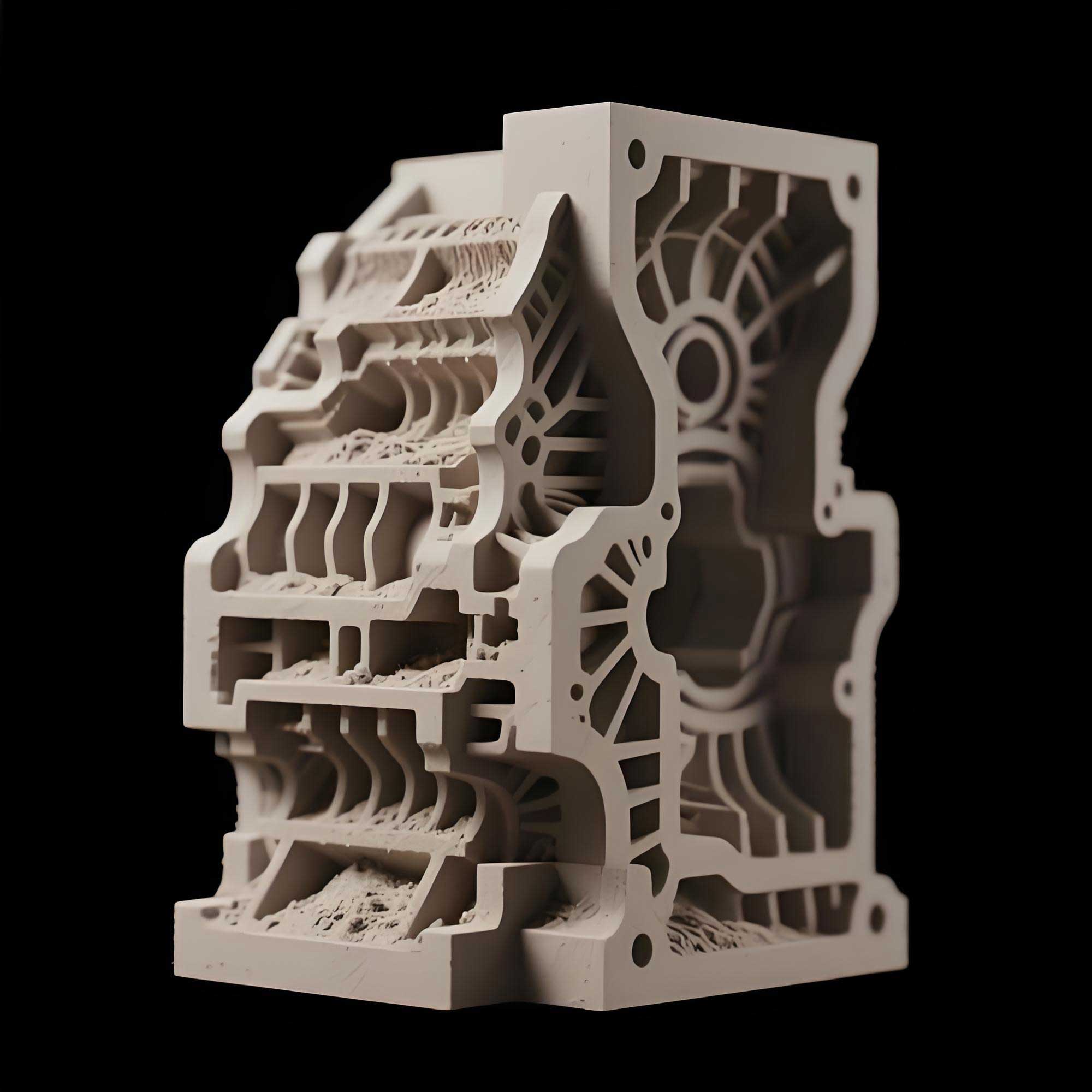
The sand molds for the pulping rotor were manufactured using a 3D sand printing machine, model VX2000. The process employs GS15-type silica sand, a special 3DP resin as binder, a 3DP-specific curing agent, and a 3DP-specific cleaning agent. The maximum printable mold size is 2000 mm × 1000 mm × 1000 mm. The dimensional accuracy of the printed mold is within ±0.3 mm. The layer printing time is ≤32 seconds per layer, with a layer thickness of 0.3 mm. The resin addition was 1.2% by weight of sand, and the curing agent addition was 0.3%. The resulting 3D printed sand mold achieved a compressive strength of 1.4 MPa. The upper and lower sand molds were printed separately, and they were subsequently assembled with core alignment. This approach allows the complex internal cavity of the rotor to be created without traditional core boxes, significantly improving mold dimensional consistency and surface quality.
The use of 3D sand printing completely eliminates the need for wooden patterns. For this rotor, the volume of the printed sand mold was 0.48 m³. The raw material cost for the sand was approximately 0.35 万元/m³, leading to a total raw material cost of about 0.168 万元. In contrast, the estimated cost of a wooden pattern would have been around 3 万元. Therefore, the single-piece cost of 3D sand printing is dramatically lower than that of traditional pattern making, particularly for small-batch and complex castings. The production cycle for the mold was reduced from a minimum of 20 days for the wooden pattern to just 1 day for 3D printing, representing a significant acceleration of the overall manufacturing timeline.
3.6 Melting and Pouring
The steel was melted using a combination of an alkaline electric arc furnace and an AOD (Argon Oxygen Decarburization) refining furnace. To ensure satisfactory corrosion and wear resistance, the carbon content was strictly controlled below 0.03%, and the impurity elements phosphorus and sulfur were also minimized. After tapping, the molten steel was held in the ladle for more than 5 minutes to allow oxides and inclusions to float to the surface. The pouring temperature was controlled at 1560–1580 °C, and a bottom-pour ladle with a φ50 mm nozzle was used to achieve a controlled filling rate.
3.7 Heat Treatment
The as-cast rotor was subjected to a normalization and tempering heat treatment. The normalization temperature was (1020 ± 10) °C with a holding time of 2 hours, followed by tempering at (600 ± 10) °C for 4 hours. The heating rate was limited to ≤100 °C/h in the temperature range of 300–600 °C, and ≤80 °C/h in the range of 600–1020 °C. This heat treatment schedule was designed to achieve the required mechanical properties of martensitic stainless steel, providing a good balance of strength, toughness, and hardness.
4. Solidification Simulation Using Procast
To verify and optimize the proposed casting process, I performed numerical simulations using Procast software. The simulation setup involved meshing the 3D model of the casting with gating and risers. The material properties of ZG06Cr13Ni4Mo were assigned, and the interfacial heat transfer coefficient was set to 500 W/(m²·K). The pouring temperature was 1580 °C, the initial ambient temperature was 25 °C, and the filling time was 6 seconds with a pouring rate of 50 kg/s. The cooling occurred by natural air convection.
The simulation results provided the temperature field evolution during solidification. Figure 7 (in the original article) showed the temperature distribution at the end of solidification, indicating that the risers remained the last to solidify, thus providing adequate feeding to the casting. The shrinkage porosity and cavity distribution predicted by the simulation is shown in Figure 8. The simulation revealed no major shrinkage defects in the structural sections, except for minor porosity confined to the riser areas, which would be removed during riser cutting. This confirms that the designed riser system was effective in feeding all critical regions, including the blade roots and the central hub.
To quantitatively evaluate the feeding efficiency, the modulus of the casting sections was compared with the modulus of the risers. The modulus \(M\) is defined as the ratio of volume to cooling surface area:
$$M = \frac{V}{A}$$
For the main body of the rotor, the calculated modulus was approximately 2.8 cm, while the central riser had a modulus of 4.5 cm. The insulating risers had an effective modulus of 1.8 cm, which was greater than the local modulus of the blade root sections (about 1.2 cm). Thus, the solidification criterion was satisfied:
$$M_{\text{riser}} > f_c \cdot M_{\text{casting}}$$
where \(f_c\) is a safety factor typically taken as 1.2. This analysis confirms the validity of the riser design.
The process yield was calculated as the ratio of the casting mass to the total poured mass:
$$\eta = \frac{m_{\text{casting}}}{m_{\text{poured}}} = \frac{187}{312} \times 100\% \approx 60\%$$
This yield is considered excellent for a steel casting of this complexity, especially when compared to conventional processes that often achieve yields in the range of 50-55%. The optimization of the riser dimensions through simulation contributed to this improved yield.
5. Experimental Verification
5.1 Dimensional Inspection
After the casting was completed, the rotor underwent fettling, riser cutting, heat treatment, and shot blasting. The dimensional accuracy of the eight blades was verified using a surface plate and height gauge. All eight blade heights were consistent and within tolerance, demonstrating the superior dimensional control achieved by 3D sand printing. Unlike traditional sand molds made from wooden patterns, the 3D printed mold does not suffer from pattern wear or draft angle deviations, resulting in more uniform and precise blade geometry.
5.2 Ultrasonic Testing
The rotor was subjected to ultrasonic inspection in accordance with ASTM A609-12. The examination covered the entire volume of the casting, with particular attention to the blade roots and the central hub. No internal discontinuities exceeding the Grade 2 limit were detected. The absence of shrinkage cavities and large porosity indicates that the feeding system was correctly designed, and the bottom gating system minimized the entrapment of slag and gases.
5.3 Chemical Composition and Mechanical Properties
Samples were taken from the casting for chemical analysis and tensile testing. The results, presented in Tables 3 and 4, confirm that the composition and mechanical properties satisfy the specifications. The carbon content was measured at 0.028%, well below the maximum of 0.06%, which is beneficial for corrosion resistance. The yield strength reached 680 MPa, and the tensile strength was 820 MPa, both exceeding the minimum requirements. The elongation was 18% and the impact energy was 68 J, indicating good ductility and toughness.
| C | Si | Mn | S | P | Cr | Ni | Mo |
|---|---|---|---|---|---|---|---|
| 0.028 | 0.65 | 0.85 | 0.012 | 0.018 | 12.5 | 4.2 | 0.6 |
| Yield strength \(R_{p0.2}\) (MPa) | Tensile strength \(R_m\) (MPa) | Elongation \(A_5\) (%) | Reduction of area \(Z\) (%) | Impact energy \(KV\) (J) | Hardness (HBW) |
|---|---|---|---|---|---|
| 680 | 820 | 18 | 42 | 68 | 255 |
5.4 Three-Dimensional Scanning
To fully evaluate the dimensional conformance of the rotor, a three-dimensional scanning was performed using an optical scanner. The scan data were compared with the nominal CAD model. The analysis showed that the maximum deviation was within ±0.8 mm across the entire surface, and the blade-to-blade spacing was uniform. Such accuracy is difficult to achieve with traditional wooden pattern molding, where pattern deformation and mold shift can lead to deviations exceeding 2 mm. The high dimensional accuracy of the rotor is crucial for its dynamic balance and smooth operation at high rotational speeds.
6. Cost and Production Cycle Comparison
To quantify the benefits of 3D sand printing, a cost comparison was conducted between the traditional wooden pattern process and the 3D printed sand mold process for a single pulping rotor. The results are summarized in Table 5.
| Item | Traditional wooden pattern | 3D sand printing |
|---|---|---|
| Pattern/mold production time | ≥20 days | 1 day |
| Cost | ~3 万元 | ~0.168 万元 |
| Draft angle required | Yes | No |
| Dimensional accuracy | ±2 mm (typical) | ±0.3 mm (mold) |
| Mold assembly complexity | High | Moderate (simplified) |
| Surface finish of sand mold | Lower | Higher |
From Table 5, it is evident that 3D sand printing offers a substantial reduction in both lead time and cost for small-batch production. The elimination of the expensive and time-consuming pattern making is particularly advantageous when producing complex castings with frequent design changes or replacement parts.
7. Discussion
The successful production of the pulping rotor using 3D sand printing and Procast simulation highlights the synergy between advanced simulation and additive manufacturing. The simulation allowed me to optimize the riser geometry and placement without physical trial runs, saving both material and time. The final riser design led to a yield of 60%, which is significantly higher than the typical 50% for similar castings produced with conventional practice. The use of insulating risers at the blade roots proved to be highly effective in preventing shrinkage defects in these thin, critical sections.
3D sand printing also provides freedom in designing the gating system. In this process, the bottom gating system was required to supply molten steel to the entire rotor cavity through a central sprue. With 3D printing, the gating channels can be made with smoother transitions and optimized cross-sections, reducing turbulence and erosion. Moreover, the precise dimensions of the printed mold ensured that the cast rotor had a uniform wall thickness, which is essential for consistent solidification and mechanical properties.
Another notable advantage of 3D sand printing is the ability to produce multiple identical molds with tight tolerances. This consistency is valuable when a small batch of rotors is required for a production line, as it ensures interchangeable parts. The printed sand molds also exhibit superior permeability compared to manually rammed molds, facilitating gas escape and reducing the risk of gas defects.
One challenge encountered was the handling and assembly of the large sand mold parts. The upper and lower halves of the mold weighed approximately 120 kg each after printing. Careful handling and alignment were necessary to avoid damage to the delicate blade impressions. However, the repeatability of 3D printing allowed for precise alignment using printed registration features, which simplified the assembly process.
8. Conclusion
In this article, I have demonstrated a complete casting process for a pulping rotor using 3D sand printing and Procast simulation. The following conclusions can be drawn:
1) The Procast simulation successfully validated the casting process design, allowing for the optimization of riser dimensions and achieving a process yield of 60%. The predicted shrinkage defects were located only in the risers, confirming adequate feeding of the casting.
2) The use of 3D sand printing for the production of complex pulping rotor castings significantly improves production efficiency. For single-piece or small-batch production of complex rotors, 3D sand printing is considerably more cost-effective than traditional wooden pattern making. The mold preparation time was reduced from 20 days to 1 day, and the cost was reduced by more than an order of magnitude.
3) The mold parting and assembly were facilitated by 3D sand printing, and the dimensional accuracy of the cast blades was greatly enhanced. The uniform compaction of the printed sand provided a more consistent mold hardness, which translated to improved dimensional consistency of the rotor blades. The final casting met all technical requirements, including chemical composition, mechanical properties, ultrasonic quality, and dimensional tolerances.
4) This integrated approach, combining 3D sand printing with numerical simulation, is a powerful methodology for efficiently producing high-quality, complex steel castings. It is especially beneficial for the pulp and paper industry, where equipment components often have complicated geometries and are required in limited quantities.
In summary, 3D sand printing has transformed the manufacturing of pulping rotors by eliminating the bottleneck of pattern making and providing exceptional design flexibility. The synergy with casting simulation ensures a robust and cost-effective process, paving the way for broader adoption of this technology in the foundry industry.