
1. Introduction
The automotive industry has been under immense pressure to reduce vehicle weight in response to increasingly stringent emission regulations and environmental concerns. Lightweight construction has become a fundamental development trend, and one of the most effective strategies to achieve this goal is the substitution of traditional ferrous materials with aluminum alloys. Among the various automotive components, the cylinder head is a critical powertrain part that operates under extreme conditions of high temperature (up to 300°C) and high pressure (approximately 70 MPa). The cylinder head must combine structural integrity with good heat dissipation and complex internal passages for the intake/exhaust system, water jacket, and oil gallery. As modern engine designs move toward higher power density and improved thermal efficiency, cylinder head geometries have become increasingly complex, with thinner walls (typically around 3–5 mm) and more intricate internal cooling channels.
This evolution toward compact and thin-walled designs has placed unprecedented demands on the casting process. The main challenge lies in fully filling thin-section molds with molten aluminum alloy while avoiding defects such as misruns, cold shuts, gas porosity, shrinkage cavities, and shrinkage porosity. Traditional gravity casting methods often struggle to meet these requirements for complex thin-walled aluminum components. The core obstacle is that during mold filling, the gas back-pressure inside the mold cavity increases as the molten metal advances, especially when the alloy tends to solidify rapidly in thin sections. Furthermore, sand molds made from resin-coated sand generate gas upon contact with high-temperature melt, compounding the problem. This often leads to insufficient filling, gas entrapment, and porosity in finished castings.
In response to these challenges, vacuum casting technology has emerged as a promising solution. By applying a vacuum to the mold environment, the back-pressure of gas in the mold cavity can be significantly reduced, thereby enhancing the mold-filling capability of the molten alloy. Simultaneously, the surrounding vacuum environment facilitates the removal of gases generated from the resin binder, reduces the hydrogen content in the melt, and generally improves the soundness and mechanical properties of the resulting castings. However, integrating vacuum casting with sand mold technology for rapid prototyping or small-batch production has not been systematically explored, particularly in the context of highly complex automotive components.
On the other hand, the lead time for developing a new engine cylinder head is a critical factor for OEMs to gain a competitive edge. Traditional tooling methods using machined metal molds or wooden patterns require significant investment in time and money, often 5–10 months and more than 800,000 RMB for a production-intent mold set. Moreover, any design modifications during the development phase inevitably require expensive rework. To overcome this bottleneck, 3D sand printing—an additive manufacturing technology based on selective laser sintering (SLS) of resin-coated sand—has been widely adopted to produce sand molds and cores directly from computer-aided design (CAD) models without the need for physical tooling. This approach significantly accelerates the prototyping process and allows for cost-effective engineering iteration. Figure 1 illustrates a typical application of 3D sand printing for casting production.
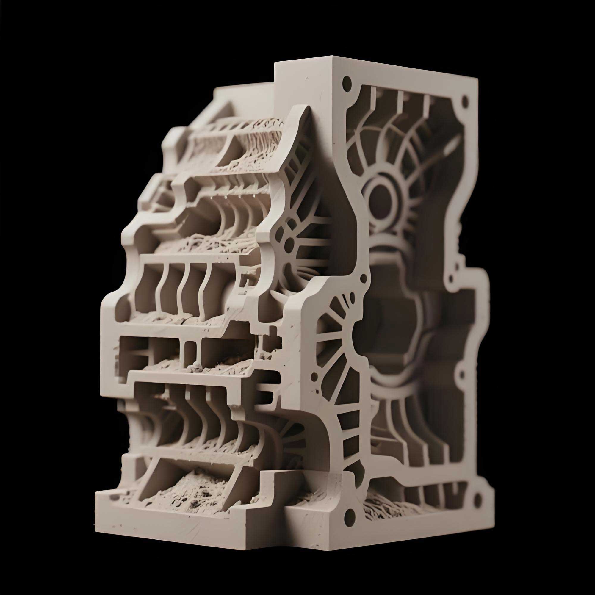
Although 3D printing of sand cores and molds is now a fairly mature technology, its integration with vacuum casting has seen limited application. A critical gap exists in understanding how process parameters such as vacuum level and pouring temperature influence the filling behavior, microstructure evolution, and mechanical properties of thin-walled aluminum alloy castings. While SLS technology provides an efficient route for mold preparation, traditional gravity casting with these resin-bonded sand molds often suffers from a high incidence of defects—specifically gas porosity near the intake/exhaust ports, shrinkage in thick sections, and widespread pinholes on machined surfaces. These defects are predominantly caused by gas generation from the resin binder (phenolic resin and hexamethylenetetramine hardener) at elevated temperatures and the limited heat dissipation of the sand mold.
In this thesis, a novel vacuum-assisted casting process was developed specifically for components made using 3D sand printing molds. The primary objective of this work is to solve the problem of gas-related porosity and insufficient mold filling in gravity-cast cylinder heads produced from 3D-printed sand molds. The research systematically investigated the influence of two key process parameters: vacuum degree inside the casting chamber and pouring temperature of the melt. Through a series of designed experiments using test bars with different wall thicknesses and geometries, the process window was established and optimized. The final manufacturing route of additive-manufactured sand molds combined with vacuum casting was, for the first time, applied to the trial production of a functional cylinder head sample, and the resulting component was thoroughly evaluated in terms of external quality, internal soundness, microstructure, mechanical properties, and dimensional accuracy.
2. Experimental Procedure
2.1 Materials and Equipment
The alloy used in this study was AC4B aluminum alloy (similar to Chinese designation ZL106, AlSi8Cu1Mg). The chemical composition is presented in Table 1.
| Element | Si | Cu | Mg | Zn | Fe | Mn | Ni | Ti | Pb | Sn | Cr | Al |
|---|---|---|---|---|---|---|---|---|---|---|---|---|
| AC4B | 7.0–10.0 | 2.0–4.0 | ≤0.5 | ≤1.0 | ≤1.0 | ≤0.5 | ≤0.35 | ≤0.2 | ≤0.2 | ≤0.1 | ≤0.2 | Balance |
This alloy offers excellent castability, good mechanical properties at both room and elevated temperatures, and is widely employed for thin-walled cast components requiring high structural integrity. The sand molds were fabricated from resin-coated sand consisting of ceramsite base sand, phenolic resin binder, hexamethylenetetramine hardener, and various additives.
Selective laser sintering rapid prototyping equipment (model HRPS-V), developed by Huazhong University of Science and Technology, was used for the production of the sand molds and cores. The maximum forming envelope of this machine is 1000 mm x 1000 mm x 600 mm, with a sintering layer thickness adjustable between 0.1–0.35 mm. The system features a CO2 laser, dynamic focusing mirrors, a temperature-controlled powder bed, and specialized software (PowerRP) that processes triangulated STL geometry data and generates slicing paths for laser scanning.
2.2 Design and Fabrication of Vacuum Casting Apparatus
A special vacuum casting device was designed and manufactured in-house for this research. The design philosophy was rooted in previous observations of vacuum casting systems and tailored specifically to the constraints of 3D-printed sand molds. Two different configurations were initially considered. In the first configuration, only the mold was placed inside a sealed vacuum chamber, while the ladle containing the molten alloy remained in the atmosphere. A flow control valve or a stopper rod was planned to initiate pouring by creating a pressure differential. However, this design was rejected due to safety concerns, the risk of uncontrolled melt delivery, and a high probability of turbulent flow and melt oxidation because the metal stream would pass through a gas interface. Moreover, this dual-chamber approach would make it difficult to control the actual pouring process in a reproducible way.
The second configuration, which was ultimately adopted, places both the ladle containing the melt and the assembled sand mold inside a single vacuum chamber. This setup allows for simultaneous evacuation of the entire environment, thereby ensuring that both the mold cavity and the free surface of the melt are subjected to the same reduced pressure. This design ensures that the flow of metal into the mold is driven purely by gravity head, without any additional pressure differential that could cause sudden or impulsive filling. It also allows for dissipation of dissolved hydrogen from the melt prior to pouring and reduces contact with the atmosphere during the entire pouring operation. Figure 2 prototyped the final construction, which consists of several integral components: a stainless steel vacuum chamber, a hinged door on the front, a viewport, a vacuum gauge, a rotation mechanism for controlled tipping of the ladle, a water-ring vacuum pump unit with a surge tank, a filter, an external control cabinet, and interconnecting isolation valves and piping.
The water-ring vacuum pump was chosen specifically for this application because of its capacity to handle a certain amount of dust (from sand molds), absorb water vapor (released during casting), and tolerate elevated gas temperatures. The maximum attainable pressure difference of this vacuum system is approximately -0.09 MPa relative to atmospheric pressure, with a pumping capacity of 4.66 m³/min. This order of magnitude of vacuum level is sufficient to create the desired pressure reduction in the mold cavity without the need for a high-vacuum system. During the filling stage, the vacuum chamber is sealed, and the pump continuously removes gas until the preset pressure is reached and stabilized. After the melt has been poured into the mold, the pump continues to run until the metal has solidified sufficiently to maintain its shape, at which point the chamber is vented to allow cooling at atmospheric pressure.
2.3 Mold Preparation through 3D Sand Printing
The CAD models of the various test bars and the target cylinder head were created using Pro/E. The solid models were exported in STL format into the RP Power job control software. The slicing parameters were chosen based on previous trials. For the test bar molds, a layer thickness of 0.2 mm was selected, while for the more intricate cylinder head molds, 0.25 mm was used. The laser power, scanning speed, and sintering temperature were maintained in the ranges typically used for resin-coated sand printing. Figure 3 shows the raw 3D-printed sand mold(s) and the post-cured molds. The porous sand structure with the new binder is visible, demonstrating the ability of this technology to create complex geometries without parting lines or draft angle constraints.
After printing, loose sand around each part was removed, and all the mold components were subjected to a post-curing heat treatment in an air circulation oven. During this step, the components were embedded in glass beads to avoid deformation, then heated to 200°C and held for 3 hours. This post-curing step partially melts and cross-links the phenolic resin, thereby increasing the strength of the sand molds and reducing the amount of volatiles that could be released during pouring. This is a critical step to minimize the gas evolution in the subsequent casting stage.
2.4 Melting and Casting Process
Prior to melting, the AC4B ingots and some returning scrap (less than 30% of total charge) were weighed and charged into a resistance furnace. The melt was heated to approximately 730°C. Refining flux was added to the melt surface for gas and oxide removal. A rotary impeller degassing unit with a rotation speed of 260 rpm was subsequently used to purge the melt with dry nitrogen for 15 min, which effectively reduces dissolved hydrogen to levels below 0.15 mL/100g Al. The melt was then skimmed and held still at temperature. All melting tools and the ladle were cleaned, coated, and preheated before contact with molten aluminum to avoid any contamination and to reduce hydrogen pickup.
The experimental program encompassed two independent series of casting trials. In the first series, the pouring temperature was kept constant at 710°C, and the vacuum level was varied across four conditions: 0 MPa (atmospheric pressure), -0.02 MPa, -0.04 MPa, and -0.06 MPa. In the second series, the vacuum level was fixed at -0.04 MPa (based on the results from the first series), and the pouring temperature was varied from 620°C to 670°C. For comparison, some additional reference samples were cast at atmospheric pressure at the same temperature levels (i.e., gravity casting). The detailed experiment parameters are listed in Table 2. In every trial, the melt temperature was monitored with a thermocouple directly inserted into the ladle, and filling was started when the melt reached the target temperature.
| Series | Sample No. | Pouring temperature (°C) | Vacuum level (MPa) | Notes |
|---|---|---|---|---|
| I | 1 | 710 | 0 | Gravity reference |
| I | 2 | 710 | -0.02 | Low vacuum |
| I | 3 | 710 | -0.04 | Intermediate vacuum |
| I | 4 | 710 | -0.06 | High vacuum |
| II | 5 | 670 | -0.04 | High temperature |
| II | 6 | 650 | -0.04 | Intermediate temperature |
| II | 7 | 620 | -0.04 | Low temperature |
| II | 8 | 670 | 0 | Gravity reference |
| II | 9 | 650 | 0 | Gravity reference |
| II | 10 | 620 | 0 | Gravity reference |
2.5 Testing and Characterization Methods
To understand the effect of vacuum on mold-filling capacity, two test coupons with different thicknesses were designed. One is a stepped plate profile with a width of 30 mm, a thickness of 3 mm over one-half the length and 12 mm over the other half, and a total length of 260 mm. This design allows evaluation of both thin and thick section filling in a single pour, where the length of the 3 mm section that was completely filled serves as a quantitative metric of mold-filling ability. The second specimen was a standardized tensile test bar with a reduced section diameter of 12 mm, designed to measure the influence of pouring temperature on mechanical properties.
For microstructural investigation, samples were sectioned from identical locations of the cast bars, ground progressively on silicon carbide abrasive papers (from #240 up to #2000 grit), polished with diamond paste (1 µm), and then etched with a 0.5 vol.% HF solution to reveal the metallurgical structure. Optical microscopy was performed using a Leica microscope. The secondary dendrite arm spacing (SDAS) was measured using a linear intercept method, where the total length of a group of secondary dendrite arms is divided by the number of arms, corrected for the magnification. For statistical validity, at least five groups of dendritic structures were measured per sample.
The tensile properties were evaluated at room temperature using a universal testing machine at a crosshead speed of 2 mm/min. The tensile test bars were machined according to the Chinese national standard GB/T 6397-86, maintaining a gauge diameter of 10 mm and gauge length of 50 mm. Interrupted immersion density measurement was implemented on multiple small specimens (approximately 10 mm x 10 mm x 10 mm) taken from the corresponding areas, applying Archimedes’ principle. The density was calculated as follows:
\[
\rho = \frac{M_1}{M_1 – M_2} \rho_{water}
\]
where \(M_1\) is the mass of the sample in air, \(M_2\) is the apparent mass of the sample suspended in deionized water, and \(\rho_{water}\) is the density of water at the measurement temperature. reported values represent the average of at least three measurements. The porosity level of the fractured cross sections was examined via optical microscopy and conventional image analysis, allowing a semi-quantitative comparison of pore size and distribution.
Brinell hardness (HB) was measured on the polished surface using a steel ball indenter with a diameter of 5 mm and a testing load of 2452 N, applied for 30 seconds. The hardness was converted from the indentation diameter using the standard relationship:
\[
HB = \frac{0.102 \, F}{\frac{\pi D}{2} \left(D – \sqrt{D^2 – d^2}\right)}
\]
where \(F\) is the applied force, \(D\) is the diameter of the ball indenter, and \(d\) is the diameter of the residual indentation. After casting and initial evaluation, the test specimens and sectioned cylinder head samples were subjected to a heat treatment consisting of solution annealing at 515°C for 4 hours, quenching in hot water (around 60–80°C), followed by artificial aging at 185°C for 4 hours.
3. Research Findings and Discussion
3.1 Effect of Vacuum Level on Mold-Filling Capacity
The influence of applied vacuum on the filling length of the stepped test bar is presented in Table 3. The quantity reported is the fluidity length, which corresponds to the total length along the test bar from the gate side to the leading edge that was fully filled. All castings were produced at a melt temperature of 710°C.
| Vacuum level (MPa) | Filling length of 3 mm section (mm) | Filling length of 12 mm section (mm) |
|---|---|---|
| 0 | 120 | 260 (full) |
| -0.02 | 223 | 260 (full) |
| -0.04 | 260 (full) | 260 (full) |
| -0.06 | 260 (full) | 260 (full) |
As can be seen from Table 3, the thickness of 12 mm was filled to full length in all cases, regardless of the vacuum level. This indicates that for relatively thicker sections, the gas back-pressure in the cavity has only a moderate effect on the filling end point because a larger cross-section provides a more favorable surface-to-volume ratio, lower friction losses, and slower cooling. However, the behavior of the 3 mm thin section was more dramatic. When no vacuum was applied, the metal solidified after filling a length of 120 mm. Observing the tip of the flow, it was evident that the melt had gradually lost its superheat, its flow front had cooled, and eventually the surface tension force had become the dominant resistive factor, causing the leading edge to stop. With a slight vacuum of -0.02 MPa, the filling length increased nearly two-fold to 223 mm. At a vacuum of -0.04 MPa, the thin section filled to its full length of 260 mm. Increasing the vacuum to -0.06 MPa produced no substantial improvement beyond what was already achieved at -0.04 MPa.
From a fluid mechanics perspective, the resistance to flow of the liquid metal front can be considered as the sum of the inertial force, gravity force, surface tension (Laplace) force, and viscous shear stress. The gas back-pressure acts as a throttle opposing the driving gravity head. In a closed mold cavity, the gas initially present in the cavity and the gas evolved from the resin binder upon contact with the molten metal induce a pressure that increases while molten metal is penetrating into the mold. The gas back-pressure term can be expressed as:
\[
P_g = \frac{N \cdot k_B \cdot T}{V}
\]
where \(N\) is the number of gas molecules in the cavity, \(k_B\) is Boltzmann’s constant, \(T\) is the temperature, and \(V\) is the remaining cavity volume. When a vacuum is applied, the initial gas pressure is reduced; hence, the rise rate of \(P_g\) during pouring becomes less severe. Moreover, the suction pressure difference across the sand mold assists in directing the gases released from the binder into the surrounding sand rather than into the flowing alloy, a phenomenon analogous to air evacuation in V-process casting. Therefore, the melting metal can maintain a higher degree of superheat at the flow front for a longer distance. The especially large improvement from -0.02 MPa to -0.04 MPa indicates that at moderate pressure reductions, the system is still sensitive to changes in vacuum; however, once most of the free gas volume is removed, further increase of vacuum degree offers diminishing returns because the residual gas originates from diffusion through the mold walls or from the binder decomposition, and thus cannot be entirely eliminated even at high vacuum.
It should also be noted that for thin sections of 3 mm thickness, the contribution of surface tension is crucial. According to Young-Laplace equation, the pressure required to overcome surface tension in a rectangular channel is inversely proportional to the section thickness. In the current context, this additional pressure term is given by \(\Delta P_\sigma=\frac{4\sigma}{\delta}\), where \(\sigma\) is the surface tension of the molten alloy and \(\delta\) is the channel height. When the vacuum level is increased, the alloy has a lower tendency to form oxide films at the surface because of the reduced oxygen partial pressure, thereby lowering the effective surface stress at the flow front and improving the fill capability. The final recommendation derived from these experiments was to set the vacuum level at -0.04 MPa to -0.06 MPa as the optimal process window for this combination of alloy and sand mold system.
3.2 Effect of Vacuum on Density and Section Porosity
To further assess the internal integrity of the cast sections, density measurements were performed on samples taken from the 12 mm thick bars. Table 4 shows the density values obtained at each vacuum level. The reference theoretical density of the fully solid AC4B alloy is approximately 2.77 g/cm³. As expected, the density values are slightly lower than theoretical density because of the presence of some porosity. Nevertheless, a monotonic increase in density with increasing vacuum level was observed.
| Vacuum level (MPa) | Sample 1 density (g/cm³) | Sample 2 density (g/cm³) | Sample 3 density (g/cm³) | Average density (g/cm³) |
|---|---|---|---|---|
| 0 | 2.7080 | 2.7102 | 2.7154 | 2.7112 |
| -0.02 | 2.7168 | 2.7146 | 2.7231 | 2.7182 |
| -0.04 | 2.7211 | 2.7237 | 2.7294 | 2.7247 |
| -0.06 | 2.7376 | 2.7375 | 2.7375 | 2.7375 |
The density improvement from the as-cast condition at atmospheric pressure to the highest vacuum level was about 0.026 g/cm³, which is around 1.0% relative improvement. This change is not merely due to the elimination of a small fraction of gas voids but also due to a more structurally sound solidification. This behavior can be interpreted through the lens of reduced initial gas content and reduced back-pressure during mold filling. A lower pressure environment shifts the equilibrium of dissolved hydrogen in the melt. Henry’s law suggests that the solubility of a diatomic gas in a liquid is proportional to the square root of its partial pressure. At reduced partial pressure of hydrogen in the surrounding atmosphere, the equilibrium hydrogen content in the melt decreases; hence, less hydrogen is available to form porosity upon solidification.
In addition to density measurements, the polished cross-sections were examined under the optical microscope to compare the pore size distribution at 0 MPa and -0.04 MPa. Image analysis confirmed a significantly lower fraction of visible pores in the vacuum-cast samples. In the gravity-cast samples, a cluster-like distribution of large pores (diameter ranging from 50 µm to 200 µm) was observed. In contrast, the vacuum-cast samples showed only a few small, isolated porosity spots. This was further confirmed by the fact that vacuum-cast samples exhibited a more homogeneous microstructure from the surface to the center of the cross-section. The reduction in porosity is particularly pronounced near the surface of the castings, where the rapid cooling promotes gas entrapment in gravity casting. Under vacuum, the driving force for gas bubble nucleation is substantially reduced, and the gas that does form tends to nucleate late and grow slowly, allowing it to be pushed along the solidification front toward the riser.
3.3 Effect of Pouring Temperature on Filling Ability
The second major parameter investigated in this research was the pouring temperature. A lower pouring temperature is desirable because it reduces the total amount of shrinkage that must be compensated by feeding, lowers gas adsorption and oxidation, and refines the solidification microstructure. However, if the pouring temperature is too low, the melt viscosity and solid fraction increase, leading to incomplete filling. Hence, there exists a minimum pouring temperature below which the casting cannot be filled completely. Understanding how vacuum can lower this threshold was one of the core objectives of this study.
Table 5 shows a compact overview of the filling behavior of the tensile test bar mold with respect to pouring temperature under two environments: atmospheric pressure and a vacuum level of -0.04 MPa. The test bar had a diameter of 12 mm in the reduced section and 16 mm in the gripping ends.
| Pouring temp. (°C) | Vacuum: 0 MPa | Vacuum: -0.04 MPa |
|---|---|---|
| 670 | Full filling | Full filling |
| 650 | Full filling (with minor edge defect at the top) | Full filling |
| 640 | Incomplete filling | Full filling |
| 620 | Only about 50% of the gauge length filled | Gauge fully filled; only the upper gripping head is slightly short |
The reference samples cast at atmospheric pressure started to exhibit incomplete filling when the pouring temperature dropped to 640°C. At 620°C, the melt became noticeably viscous, and the flow stopped after filling only a fraction of the test bar length. On the other hand, under a vacuum of -0.04 MPa, the mold was completely filled at 640°C, and even at 620°C, the critical gauge section was fully formed. Only the upper grip end was somewhat under-filled. This result demonstrates a remarkable benefit of vacuum: the minimum pouring temperature necessary for complete mold filling can be lowered by at least 30 K, and up to 50 K depending on the complexity of the section.
The mechanism for this improvement lies in the role of gas back-pressure on the flow stopping condition. In conventional gravity casting, the molten metal front decelerates because the gas pressure in front of the metal increases as the air in the cavity is compressed by the entering liquid. This compression heats the gas, further increasing its pressure. Eventually, the driving pressure head is balanced by the back-pressure plus friction losses, and the flow stops. When this occurs before the metal has completely filled the mold, a misrun is formed. In a vacuum environment, the initial cavity pressure is nearly zero; therefore, the same volume of metal can penetrate a much longer distance before the accumulated back-pressure becomes significant. This is especially impactful in thin-walled molds, where the volume of the cavity is large relative to the cross-sectional area of the flow, and thus the relative pressure increase is amplified.
3.4 Microstructural Evolution at Different Pouring Temperatures
The optical micrographs of cast samples taken from the center of the tensile gauge sections are shown in Figure 4 and described as a function of pouring temperature. At the highest temperature of 670°C, the microstructure was dominated by a columnar dendrite and rosette-like dendrite morphology. The primary columnar grains had grown with a distinct preferential direction, and well-developed secondary dendrite arms (SDAs) could be observed. At 650°C, a noteworthy transition in morphology occurred: the frequency of columnar dendrites decreased and the development of secondary arms became less prominent, while a portion of the dendrites began to fragment into more rounded and globular-like features. The overall structural homogeneity and randomness increased, indicating a shift in the solidification regime away from a strong directionally oriented growth. At a reduced pouring temperature of 620°C, which is close to the liquidus temperature for this alloy, the structural morphology further evolved into predominantly spherical or granular-like grains. Although a perfect equiaxed structure was not achieved, the morphology was undeniably more globular and less branching compared to the rose-like dendrites observed in the high-temperature casting.
This structural evolution has its origin in the strong dependence of nucleation and growth on melt undercooling. In the high-temperature casting process, the superheat of the melt is realized in a larger thermal mass, leading to a lower cooling rate and a longer solidification time. Accordingly, a smaller number of nuclei survive and grow to large sizes, and the solid/liquid interface is more likely to develop perturbances and form secondary arms. On the contrary, at a pouring temperature close to the liquidus, the melt undercooling at the mold wall is much larger at the start of solidification. Nucleation is more copious, and the particles are smaller, so they are more easily transported to and concentrated in the center. Crystal multiplication is further enhanced by the fragmentation of the primary dendrites. Given that the thermal gradient is more uniform, these nuclei tend to grow in a more isotropic fashion, leading to globular or near-globular morphologies.
These microstructural differences should have a direct consequence on the mechanical properties. The tensile test results shown in Table 6 confirm that the ultimate tensile strength (UTS) increases as the pouring temperature decreases. At 670°C, the UTS was 376 MPa. At 650°C, this rose slightly. At the lowest temperature of 620°C, the UTS reached 420 MPa, an improvement of approximately 12% over the high-temperature castings. This trend is explained by the Hall-Petch-type strengthening related to the refined grain size and the more globular and uniform microstructural features. The fine-grained and globular structure restricts the propagation of cracks along the grain boundaries, thus requiring a higher stress to achieve similar plastic deformation. Additionally, lower pouring temperature reduces the dissolved gas content, which in itself improves tensile properties by minimizing the number of micropores.
| Pouring temperature (°C) | UTS (MPa) | Elongation variation trend |
|---|---|---|
| 670 | 376 | Lower ductility |
| 650 | 385 | Moderate ductility |
| 640 | 390 | Moderate ductility |
| 620 | 420 | Higher ductility |
The fracture surfaces of the tensile test bars were analyzed by scanning electron microscopy (SEM). At a pouring temperature of 670°C, the fracture surface displayed a combination of quasi-cleavage facets and shallow dimples, consistent with a brittle-dominated failure. There were also a number of large pores that contributed to the early fracture by effectively reducing the load-bearing cross-section. At 620°C, the fracture morphology changed to a homogeneous distribution of fine and deep dimples. These are characteristic of a ductile microvoid coalescence fracture mode, indicating a higher resistance to crack propagation.
3.5 Gas Porosity and Segregation Defects
During the experiment, another important microstructural observation was made concerning gas porosity. In gravity casting at 670°C, many dispersed pinholes appeared in the micrograph. These pinholes are the result of hydrogen precipitation during solidification. The solubility of hydrogen in liquid and solid aluminum is known to be very different. At the melting point of aluminum, the ratio of hydrogen solubility in the liquid state to that in the solid state is approximately 20:1, with the liquid able to dissolve significantly more gas. When casting at a higher temperature, more hydrogen is absorbed into the liquid. As the alloy solidifies, the dissolved hydrogen is rejected from the solid phase and concentrates in the remaining liquid, eventually forming bubbles. If the melt pour temperature is too high, solidification takes longer, allowing more time for the hydrogen to diffuse and precipitate as coarse porosity. In contrast, in vacuum-cast samples at the same pouring temperature, pinholes were almost completely absent. The vacuum system removes hydrogen from the melt surface before pouring and keeps the partial pressure of hydrogen low, thereby shifting the equilibrium toward the expulsion of gas from the melt. This difference in gas content is a major contributor to the improvement in density observed in Table 4.
It is also worth noting that, at high pouring temperatures, both vacuum and gravity castings showed some evidence of micro-segregation. The high pouring temperature causes a large temperature gradient between the surface and the center, giving rise to a wide mushy zone at the solidification front. Within this zone, the evolution of dendrites with long secondary arms retards the diffusion of solute in the remaining liquid, so that the last liquid to solidify contains a higher percentage of eutectic constituents. This non-equilibrium segregation is detrimental to the uniformity of the mechanical properties. The lower pouring temperature used in vacuum casting reduces the size of the mushy zone and promotes the formation of a more finely divided, less segregated structure.
4. Application to a 3D-Printed Cylinder Head Casting
4.1 Component Analysis and Tooling Strategy
After establishing the optimized process window—namely a vacuum level of -0.04 MPa and a pouring temperature of about 650–710°C depending on the section thickness—the process was transferred to the production of an actual engine cylinder head. The cylinder head shown in Figure 5 is representative of a modern automotive four-valve engine. Its overall dimensions are approximately 450 mm in length, 180 mm in width, and 90 mm in height. The geometric complexity is remarkable: the casting consists of curved combustion-roof surfaces at the bottom, flat mating surfaces at the top for the camshaft carrier, and inward passages for intake and exhaust ports. Internally, the casting is hollowed out by an intricate sand core system that includes water jacket cores, intake-exhaust port cores, and an oil gallery core. In the as-cast condition, it must have minimal draft angles and tight dimensional tolerance to accommodate subsequent machining operations.
The sand molds and cores used for the automotive prototype casting were produced in one batch using the SLS process. A full set includes a bottom mold (which forms the combustion chamber surface), side molds (front and rear end molds), water jacket cores (which are surrounded by 4 to 5 mm thick metal walls), the intake and exhaust port cores, an oil gallery core, and a riser neck mold. Through the process of 3D sand printing, the designer has the freedom to optimize the core layout without having to worry about core pulling angles. The outer sand molds were printed in segments that could be readily assembled. The measured dimensional accuracy of the printed cores was within ±0.5 mm for the overall dimensions and within ±0.2 mm on critical sealing surfaces. Figure 5 shows the full assembly of the dry cores and molds prior to closure.
4.2 Casting and Quality Evaluation of the Cylinder Head
The gating system for the cylinder head was designed in a top-tinted riser configuration where the metal enters at the top of the casting and flows downwards by gravity. In this design, the combustion chamber face is filled first, followed by intermediate sections, and finally by the riser at the top. This enables a bottom-up solidification sequence from the combustion roof toward the risers, which is beneficial for compensating solidification shrinkage by gravity-fed liquid. However, the gravitational filling may lead to an initial turbulent phase; this is relieved by lowering the inlet velocity through the runner bars and using a curved sprue with an integrated filter to prevent oxidation films and slag from entering the casting.
Before the metal was poured, the assembled mold was placed in the vacuum chamber and the pre-prepared alloy was poured into a tip-ladle positioned directly above the sprue. After the chamber was evacuated to -0.04 MPa, the ladle was rotated, and the metal flowed gently into the mold. After about 3 minutes, when the riser surface began to solidify, the vacuum pump was switched off, and the chamber was vented to atmosphere. The solidified casting was allowed to cool in the mold for about 2 hours before shakeout. The process flow and the images of the casting operation are illustrated in Figure 6.
4.3 Evaluation of Macrostructure and Surface Quality
The shakeout casting was visually inspected. Figure 7 shows the cast cylinder head after fettling operations. According to the inspection results, all external surfaces had a smooth finish with no evidence of flash, misrun, cold shut, or surface pinholes. The combustion chamber surface and the complete water jacket cavity were cast completely. The intake and exhaust ports were open and smooth, and the core prints were intact. The cylinder head was pressure-tested with water at 200 kPa to check the fluid-tightness of the water jacket and the oil passages. No leakage was identified, indicating that the internal integrity of the component was high.
A critical comparison was made with the previous gravity-cast cylinder heads made by the same sand mold technology. The gravity-cast heads had commonly shown four types of defects: (i) gas blowholes in the area of the intake and exhaust ports (due to resin gas generation from the cores); (ii) shrinkage cavities in the thick sections near the tappet holes (caused by lack of adequate feeding); and (iii) numerous pinholes distributed over the machined surfaces. In the vacuum-cast cylinder head, none of these defects were detected. Longitudinal cross-sectioning of the cylinder head, as seen in Figure 7, confirmed that the valve guide holes, the intake and exhaust port cores, and the combustion-roof zones were fully dense. The absence of blowhole defects is associated with two main mechanisms. First, the vacuum pumps reduce gas pressure, enabling gas bubbles to nucleate in the metal and be withdrawn through the sand mold walls rather than being trapped in the casting. Second, the sand cores were pre-treated by firing at 200°C for 3 hours, which removes a fraction of the volatile resin constituents. Combined together, the mold gas attack is drastically reduced.
4.4 Microstructure and SDAS Analysis
To assess the metallurgical quality of the cylinder head, metallographic samples were taken from three strategic locations: the combustion chamber face (area a), the vicinity of the water jacket (area b), and the top camshaft face near the riser (area c). These positions correspond to different local solidification times during casting: area a is the first to solidify, area c is the last to solidify. The measured SDAS values are shown in Table 7.
| Location | SDAS (µm) | Interpretation |
|---|---|---|
| Combustion chamber face (a) | 50 | Rapid cooling, first solidified |
| Water jacket proximity (b) | 56 | Moderate cooling rate |
| Camshaft face near riser (c) | 63 | Slowest cooling, last solidified |
These results reveal a gradual increase in SDAS from the combustion face to the top face, which is consistent with a directional solidification regime from bottom to top. The local solidification time can be approximated by the SDAS to be proportional to \(\lambda_2^3\). A lower SDAS at the combustion chamber face implies a shorter local solidification time and a finer dendrite structure. This is attributed to the strong chilling effect of the bottom mold in combination with the vacuum-enhanced contact between the melt and the mold surface. The high heat extraction rate is beneficial for achieving the fine microstructure requested for the combustion chamber surface of a cylinder head.
A comparison of the microstructure of the vacuum-cast cylinder head with that of the gravity-cast one is notable. At the same location (combustion chamber face), the gravity-cast sample displayed a coarser dendrite structure with visible shrinkage pores. The vacuum-cast sample showed a more refined and more uniform network of α-Al solid solution and Al-Si eutectic. This refinement is primarily the result of the lower pouring temperature that was made possible by the vacuum-enhanced mold filling. Moreover, the reduced gas content in the metal promoted a healthier solidification with less porosity.
4.5 Mechanical Property Validation
After heat treatment, tensile test specimens were extracted from the cylinder head at the combustion chamber face, along the vertical section, and at the camshaft face. The results of the tensile tests are summarized in Table 8. Vacuum-cast samples consistently provided higher tensile strength than gravity-cast ones at the respective locations. At the combustion chamber face, the vacuum-cast sample achieved a UTS of 272 MPa, comfortably exceeding the technical specification of greater than or equal to 245 MPa. The gravity reference sample yielded around 268 MPa, which also meets the requirement but was inferior in consistency. The vertical specimen fractured near the camshaft face, which is the last solidified area and shows a lower tensile strength due to the coarser microstructure, but still stays above the specification limit.
| Sampling position | Vacuum-cast UTS (MPa) | Gravity-cast UTS (MPa) | Specification (MPa) |
|---|---|---|---|
| Combustion chamber | 272 | 268 | ≥245 |
| Vertical (from combustion to camshaft) | 264 | 255 | ≥245 |
| Camshaft face | 250 | 243 | ≥245 |
Hardness measurements were also taken at the combustion chamber face and camshaft face. Vacuum-cast cylinder heads yielded values of 107 HB at the combustion face and 98 HB at the camshaft face, both within the specified range (95–115 HB for the bottom face and 90–110 HB for the top face). The maximum hardness difference between the two areas was 9 HB, well below the allowed difference of 15 HB.
4.6 Density Verification
As shown in Table 9, the density of samples at the same three locations of the cylinder head was determined. Vacuum-cast samples showed a stable density of about 2.72 g/cm³ at the combustion chamber, slightly more than 2.71 g/cm³ at the water jacket regions and the camshaft face. Compared to the gravity-cast cylinder head, the water-jacket area shows the largest improvement, from 2.69 g/cm³ to 2.71 g/cm³. This is a significant and meaningful advance since it is the location that suffers from gas entrapment due to the presence of a large core. High local integrity is essential to prevent leakage of cooling water through the walls into the combustion zone or oil passages.
| Sampling position | Vacuum-cast density (g/cm³) | Gravity-cast density (g/cm³) |
|---|---|---|
| Combustion chamber | 2.724 | 2.713 |
| Water jacket proximity | 2.716 | 2.690 |
| Camshaft face | 2.710 | 2.695 |
The overall mechanical performance of the vacuum-cast cylinder head met all specified quality standards. Moreover, the manufacturing route was completed in a short time: CAD data processing required two days, printing of all cores and molds took another two days, post-curing and core assembly another day, casting one day, and final inspection one day. This totals to less than one week of turnaround time, which is a notable advantage for rapid product development in the automotive sector.
5. Theoretical Analysis of Vacuum Filling in Sand Molds
Based on the experiments described above, we can propose a more comprehensive theoretical framework for the filling of a 3D-printed sand mold in a vacuum chamber. Let us consider a simple case of a rectangular channel of thickness \(\delta\) and width \(w\). The pressure balance at the flow front can be written as:
\[
\rho_m g h = \frac{4\sigma}{\delta} + \Delta P_{friction} + \Delta P_{viscous} + P_{gas}(t)
\]
where \(\rho_m\) is the melt density, \(h\) is the metallostatic head, \(\sigma\) is the surface tension of the melt, \(\Delta P_{friction}\) and \(\Delta P_{viscous}\) represent the frictional and viscous pressure drops (usually modeled by the Hagen-Poiseuille equation), and \(P_{gas}(t)\) is the instantaneous gas pressure in the unfilled portion of the cavity. When vacuum is applied, the initial value of \(P_{gas}(0)\) is \(P_{vac}\), which is close to zero, whereas under atmospheric gravity casting \(P_{gas}(0) \approx 101\) kPa. For the specific geometry of our thin wall section of 3 mm, the capillary pressure \(\frac{4\sigma}{\delta}\) is of the order of 30–50 kPa, while the total driving pressure from metallostatic head is only about 20–30 kPa for a 300 mm tall filling system. Thus, in the atmospheric case, the gas back-pressure can easily stop the metal as it is compressed to a small volume. Under vacuum, the gas back-pressure term is negligible, leaving the capillary and friction terms as the main limiting factors. In this context, reducing the gas pressure helps not only in filling longer sections but also in forming sharper corners and thin-sections that would otherwise not fill due to the Laplace pressure.
Vacuum casting also has an indirect benefit with respect to feeding. During solidification, the vacuum in the chamber creates a uniform pressure gradient across the sand mold. The pressure difference between the interior of the still-liquid metal (at atmospheric chamber pressure after venting) and the mold wall improves the contact between the melt and the mold. Better thermal contact translates into more effective cooling at the mold wall. This can promote a faster solidification rate and directionality. In addition, the pressure difference allows the outer oxide layer around the casting to be pushed inward by the atmosphere after venting, potentially contributing to squeeze-out of gas porosities and the reduction of shrinkage cavities.
Another point that deserves consideration is the influence of the mold itself. The sand used for 3D printing is usually not fully dense; its permeability ranges between 1.5–3.5 cm²/(kPa·s). This permeability, which is higher than that of conventional green sand, facilitates the passage of air through the mold walls to the outside. Under vacuum, the gas that is generated at the metal-mold interface is effectively sucked away into the chamber rather than being pushed into the metal. This phenomenon further enhances the quality of the vacuum-cast component.
6. Process Optimization Recommendations
From the observed behavior, several key parameters need to be optimized when using the 3D sand printing + vacuum casting process. The first is, of course, the vacuum level. The current study demonstrates that a vacuum of -0.04 MPa is sufficient for simple shapes; more complex shapes with thin fins or long blind passages may require -0.06 MPa. However, excessively high vacuum could increase the risk of air aspiration through the mold joints or the sprue, leading to unwanted air incorporation, although the water-ring pump used in this study is limited to -0.09 MPa, and thus this risk is mitigated. The second is the pouring temperature: lower pouring temperatures are favorable for mechanical properties and internal soundness, and the vacuum enables a lower pouring temperature without reducing filling capacity. The induction of a 30–50 K reduction is significant because it reduces the energy required for superheating, reduces the casting time, and minimizes oxidation. The third important parameter is the preheating of the sand molds. Although not systematically studied in the current work, it is known from the literature that preheating the mold to 100–150°C removes residual moisture and further reduces gas evolution. This would also require some balance against the cooling rate; a too-hot mold would increase the risk of shrinkage porosity. The fourth parameter of importance is the mold coating. As the 3D-printed sand core surface is relatively rough, applying a mold wash with zircon or mica can improve the surface finish of the casting and somewhat hinder the direct chemical reaction between the metal and the resin sand. The combination of vacuum and coating has shown promising results in preliminary tests.
A further aspect of improvement arises from scenario analysis of the actual casting cycle. The duration of the vacuum application depends on the total gas load. For a cylinder head with a mold surface area of about 0.3 m², the pump used in the experiments needed about 90 seconds to reduce the chamber pressure from atmospheric to -0.04 MPa, and the pressure remained stable meanwhile. Therefore, this process still benefits from an efficient pumping system to shorten cycle time. The process is also scalable: multiple molds can be placed in a bigger chamber, and casting can be achieved by similar tilting ladles or perhaps by a bottom-fill system driven by vacuum differential, similar to low-pressure casting. The practical implications for small and medium batch production on-demand components are significant.
7. Economic and Industry Implications
The outcome of this research directly addresses the current industrial dilemma of producing cast components with complex internal geometry at low volume. The manufacturing paradigm enabled by the 3D sand printing technology offers flexibility and time-to-market advantages. Printing the mold and cores for a cylinder head directly from a CAD model avoids the costly and time-consuming pattern fabrication process. The time from geometry finalization to first cast samples can be compressed from months to just days. This technology also eliminates the storage and maintenance costs for physical patterns. Since the mold is designed digitally, engineering changes can be implemented overnight by modifying the CAD model and printing a new core.
Moreover, the vacuum casting process is implementable with relatively simple equipment. The vacuum chamber and pump unit used in this work represent a capital expenditure that is only a small fraction of a typical low-pressure or counter-pressure casting cell. The opportunity to pour the melt at lower temperature allows the use of a smaller crucible and reduces the energy consumption per casting. The reduced scrap rate (defect-free castings in this study) further contributes to cost reduction. Therefore, for those industries where the production volume is limited but the part complexity is high, such as in motorsports, aerospace, defense, and automotive research and development, the combination of 3D sand printing and vacuum casting forms a compelling business case.
In a broader perspective, this technology supports the current trend towards agile manufacturing of heavy equipment, where the goal is to produce high-performance castings on demand. As the additive manufacturing of sand molds becomes more integrated into the casting industry, it is likely to replace pattern making for even medium-sized series of engine components. The results of this thesis contribute to establishing a robust process window for the integration of SLS-printed sand molds with vacuum-assisted filling. The findings also deliver a scientific understanding of how the vacuum level influences the flow and solidification of aluminum in complex molds.
8. Conclusion
This study successfully developed and validated a vacuum-assisted casting process integrated with 3D sand printing, specifically for the production of complex thin-walled aluminum alloy castings. Based on the current results, the following conclusions can be formulated for the process of 3D-printed sand mold casting:
(1) Vacuum casting improves the mold-filling capacity of AC4B alloy significantly. In a thin-wall test bar of 3 mm thickness, the filling length increased by more than 80% when the vacuum was raised from 0 MPa to -0.02 MPa, and complete filling was achieved at -0.04 MPa. A further increase in vacuum to -0.06 MPa offered only marginal benefit. Thus, the vacuum range of -0.04 MPa to -0.06 MPa is recommended for 3D-printed sand mold casting of aluminum.
(2) Vacuum application increases the density of the castings and reduces the pore fraction. Density increased progressively from 2.7112 g/cm³ at atmospheric pressure to 2.7375 g/cm³ at -0.06 MPa. Metallographic examination confirmed a substantial reduction in the number and size of micro-pores.
(3) The minimum pouring temperature necessary to fill a tensile test bar mold is lowered by at least 30–50 K when vacuum is applied. At a pouring temperature of 620°C, which is only slightly above the liquidus, the gauge section of the test bar could be completely filled under -0.04 MPa vacuum, whereas gravity casting at the same temperature resulted in an incomplete mold fill.
(4) Lower pouring temperatures align with the benefits of vacuum, resulting in a more refined and globular microstructure. As the pouring temperature was reduced from 670°C to 620°C, the columnar dendrites transformed into rosettes and, eventually, into nearly globular grains. This structural transition increased the ultimate tensile strength from 376 MPa to 420 MPa, while also improving fracture ductility.
(5) Vacuum casting also effectively suppresses gas porosity and segregation defects that appear in the high-temperature casting of Al-Si-Cu alloys. Dissolved hydrogen is expelled during the hold under vacuum, resulting in low porosity levels and limited micro-segregation.
(6) Applying the optimized process to a 3D-printed cylinder head confirmed the feasibility. The casting was complete and free of blowhole defects. The microstructure of the combustion chamber surface showed a SDAS of 50 µm, providing an acceptable mechanical property profile. The tensile strength and Brinell hardness met the specification for the cylinder head. The density at the problematic water-jacket region improved by about 1% compared to gravity casting.
(7) The combined use of 3D sand printing and vacuum casting reduces development time from months to less than a week and provides superior casting quality, making it a suitable alternative for rapid prototyping and small-series production of complex thin-walled aluminum components.
9. Future Research Directions
Although the current study achieved its aims, there are several directions for future work. First, a deeper understanding of the fluid dynamics during vacuum filling could be obtained through computational fluid dynamics (CFD) simulations. This would allow predictions of the flow front in complex geometries under given vacuum pressures. It would also enable virtual optimization of the gating system to prevent jetting and turbulence. These simulations could be validated by watching the filling process in a transparent mold model using water analog fluids. Second, the influence of vacuum on the solidification kinetics deserves further quantitative examination. In-situ measurement of cooling curves at strategic locations in the mold would give additional insight into the rate of solidification and feeding behavior. This would enhance the understanding of the SDAS gradient that was observed. Third, for the production of cylinder heads, the application of a combined vacuum and local cooling (or even pressure support after filling) might extend the process window and reduce the possibility of shrinkage in thick sections. Fourth, the effect of the sand mold surface roughness and the application of different mold coatings on the final product quality should be systematically investigated to further enhance the surface finish. Finally, the mechanical properties of this alloy could be improved by optimizing the heat treatment cycle, potentially through two-step solution treatment and aging, to target specific SDAS values. These improvements will close the gap between prototype, limited-series, and mass production parts manufactured by this process.
To sum up, the combination of 3D sand printing with vacuum casting is a viable, efficient, and high-quality route for producing thin-walled aluminum castings. The research findings of this thesis—covering process design, parameter optimization, defect analysis, and component trial—have established a solid foundation for further industrial applications. The results are expected to contribute to the advancement of lightweight automotive components and to enable more flexible manufacturing paths in the aerospace and defense sectors as well.