
I developed and qualified an investment casting process for a large second stage turbine moving blade. The blade has a complex internal cavity, tight dimensional tolerances, and a demanding water flow requirement. Its overall envelope is approximately 351 mm × 168 mm × 89 mm. The airfoil length is 203 mm. The tip region is vulnerable to deformation during solidification. The distance between the tip waist-shaped hole and the airfoil is only about 2.6 mm, which makes shell preparation difficult. The tenon pocket on the suction side is deep, so the shell can dry poorly and produce excess metal that is difficult to remove. The internal grid is complex, and the exhaust trailing slot must be held to 1.2 mm ± 0.2 mm. Water flow testing is also required. During early trials, I observed ceramic core cracking during wax injection and low shell strength at the blade tip. I solved these issues by adjusting wax injection parameters, filling weak core areas with wax support, modifying shell-making details, and controlling melting and pouring parameters. The final castings passed fluorescence inspection, radiographic inspection, and dimensional inspection.
Full mold casting is sometimes considered for large castings because the pattern is expendable and tooling can be simplified. However, for this blade, full mold casting was not selected because the internal ceramic core must remain intact during wax injection and shell building, and the 1.2 mm exhaust slot cannot be reliably formed by a foam pattern. I compared full mold casting with investment casting and concluded that investment casting provides the necessary dimensional control, shell strength, and core stability. In full mold casting, the pattern is vaporized by the metal, but here the ceramic core must survive high-temperature pouring and then be leached out. The full mold casting route would also make it difficult to inspect the internal grid before pouring. Therefore, I focused on investment casting while keeping full mold casting as a reference for riser design and gating concepts. A typical full mold casting arrangement is shown below for comparison with the investment casting shell system.
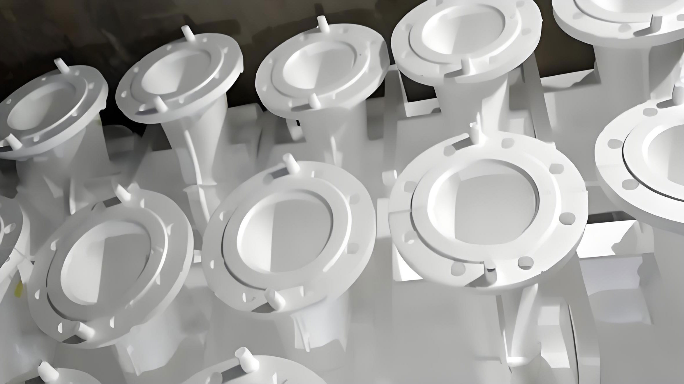
Although full mold casting can be economical for certain geometries, the thin tip, the 2.6 mm gap, and the complex ceramic core made full mold casting unsuitable for this component. I also evaluated full mold casting for the tenon pocket region, but the deep pocket would be difficult to coat uniformly in a full mold casting process. The full mold casting approach would likely produce bridging or incomplete coating in the narrow tip space. For these reasons, the production route remained investment casting.
1. Blade Geometry and Casting Challenges
The second stage moving blade is a hollow structure with a ceramic core that forms the internal cooling passages. The exhaust side has a complex grid, and the cylindrical connection near the tenon-side core print is fragile. The thinnest tip wall is only 3 mm. These features create several challenges. First, the ceramic core can crack during wax injection because the wax pressure and flow can impose bending and shear stresses on thin core sections. Second, the tip region has a narrow space of about 2.6 mm between the waist-shaped hole and the airfoil, which can cause shell bridging when coarse sand is used. Third, the deep tenon pocket on the suction side dries slowly, leading to shell delamination and excess metal. Fourth, the exhaust trailing slot must be 1.2 mm ± 0.2 mm, which requires precise core positioning and shell dimensional stability. Fifth, the water flow test demands clear and consistent internal passages.
I summarized the main geometric parameters in Table 1. These values guided the wax injection, shell-making, and melting schemes.
| Feature | Nominal value | Process implication |
|---|---|---|
| Overall envelope | 351 mm × 168 mm × 89 mm | Requires top pouring and sufficient shell strength |
| Airfoil length | 203 mm | Tip deformation risk during solidification |
| Tip waist hole to airfoil distance | ≈ 2.6 mm | Narrow space, bridging risk in shell |
| Thinnest tip wall | 3 mm | Core support and wax filling must be controlled |
| Exhaust trailing slot | 1.2 mm ± 0.2 mm | Core positioning and shell rigidity critical |
| Tenon pocket depth | Deep | Poor drying, excess metal, shell delamination |
| Internal grid | Complex | Water flow test requirement |
The dimensional tolerance for the profile was +0.75 mm / −0.5 mm. This is a tight tolerance for a casting of this size. I used the following relationship to estimate the required shell rigidity:
$$ \sigma_{\text{shell}} \geq \frac{F_{\text{metal}}}{A_{\text{contact}}} $$
where σshell is the shell strength, Fmetal is the metallostatic force, and Acontact is the contact area. This simple inequality helped me judge whether the shell layers and stucco grades were sufficient. In full mold casting, the mold strength is often lower than in investment casting, which is another reason I did not choose full mold casting for this blade.
2. Wax Pattern Scheme
The blade is hollow, and the ceramic core defines the internal passages. The exhaust side grid is complex, and the tenon-side core print has a cylindrical connection that can break. The weakest tip region has a thickness of 3 mm. Before wax injection, I filled the weak areas with R839 runner wax. The filling had to be dense and well bonded; any virtual connection between the filling wax and the ceramic core would create a defect. I used the following criteria for the filling:
$$ \text{Bond quality} = \begin{cases} \text{acceptable}, & \text{if no gap and no virtual connection} \\ \text{unacceptable}, & \text{if gap or virtual connection exists} \end{cases} $$
I adjusted the wax injection parameters to reduce core stress and improve filling. The optimized parameters are given in Table 2.
| Parameter | Value | Purpose |
|---|---|---|
| Wax cylinder temperature | 80 ± 5 °C | Control viscosity and fluidity |
| Nozzle temperature | 80 ± 5 °C | Prevent premature freezing |
| Injection pressure | 5 ± 2 bar | Fill thin sections without core damage |
| Flow rate | 40 ± 5 cc/s | Balance filling speed and core stress |
These parameters can be expressed as:
$$ T_{\text{cylinder}} = 80 \pm 5^\circ C $$
$$ T_{\text{nozzle}} = 80 \pm 5^\circ C $$
$$ P_{\text{injection}} = 5 \pm 2 \text{ bar} $$
$$ Q_{\text{wax}} = 40 \pm 5 \text{ cc/s} $$
First, I injected wax without the ceramic core to check the surface quality. The wax pattern showed only slight flow lines. Then I inserted the ceramic core and a cold wax block. The surface flow lines disappeared, but the exhaust side was not completely filled. I performed short-shot experiments at 5 s, 10 s, 12 s, 13 s, 14 s, and 15 s. The filling behavior was as follows: within the first 10 s, the basin side and the back side filled at nearly the same speed. In the final stage, the back side encapsulated faster than the basin side. As a result, the basin side exhaust edge had insufficient space for wax to enter, and the basin side exhaust edge remained unfilled.
I used the following flow continuity equation to analyze the filling imbalance:
$$ Q_{\text{total}} = Q_{\text{basin}} + Q_{\text{back}} $$
At the end of filling, Qbasin decreased because the basin side exhaust edge became a narrow gap. The back side continued to receive more wax, causing the back side to encapsulate first. To solve this, I increased the wax cylinder temperature so that the wax still had enough fluidity at the end of filling. However, the temperature could not be raised too high, because excessive wax temperature increases solidification shrinkage and can squeeze the ceramic core. The shrinkage stress can be approximated by:
$$ \sigma_{\text{core}} = E_{\text{core}} \alpha_{\text{wax}} \Delta T $$
where Ecore is the core elastic modulus, αwax is the thermal expansion coefficient of the wax, and ΔT is the temperature change. I kept the temperature within the range 80 ± 5 °C to avoid core cracking. After optimization, I pressed 10 parts. After complete cooling, I dissolved the wax and inspected the ceramic core. No cracks were found.
I also designed the wax pattern assembly. The blade length in the Z direction is 351 mm. A top pouring scheme can satisfy feeding. Based on the blade envelope and the tenon Z-section length of about 80 mm, I set the riser width to 75 mm and the riser height to about 40 mm. I used a split riser. First, I joined the riser to the tenon. Then I bonded the remaining part with binder wax. The transition between the part and the riser was smooth. The riser dimensions are summarized in Table 3.
| Riser parameter | Value | Note |
|---|---|---|
| Riser width | 75 mm | Based on tenon section |
| Riser height | ≈ 40 mm | Adjusted for metallurgical quality |
| Pouring position | Top | Feeds the 351 mm length |
| Assembly method | Split riser | Riser first bonded to tenon, then remaining part |
Full mold casting would not allow this split riser approach in the same way because the foam pattern is a single expendable body. In full mold casting, the riser is often formed together with the pattern, which reduces flexibility in feeding design. For this blade, the split riser was important for smooth wax flow and later shell preparation.
3. Shell-Making Scheme
The shell must withstand the metallostatic pressure and thermal shock during pouring. The deep tenon pocket and the narrow tip space are the two most critical regions. The tenon pocket dries slowly because it is deep and enclosed. The tip space is about 2.6 mm wide, so coarse stucco can bridge across the gap. Bridging reduces shell strength and can cause core shift or incomplete shell coverage. I modified the shell-making process to address these issues.
For the tenon pocket, I used the following procedure:
- After the transition layer, I dried the shell for 2 h.
- Then I inserted a compressed air tube into the pocket to force air circulation.
- Before slurry dipping, I cleaned loose sand from the basin-side and back-side tenon pockets with compressed air.
- This cleaning step prevented shell delamination.
For the narrow tip space, I used finer stucco for layers 2 and 3. I selected 30–60 mesh mullite sand. Before each layer, I cleaned loose sand from the narrow space. The shell-making scheme is given in Table 4.
| Layer | Powder and specification | Slurry viscosity / s | Stucco material and specification |
|---|---|---|---|
| 1 | Zircon sand, 325 mesh | 36 | Zircon sand, 100 mesh |
| 2–3 | Mullite powder, 200 mesh | 15 | Mullite sand, 30–60 mesh |
| 4–10 | Mullite powder, 200 mesh | 12 | Mullite sand, 16–30 mesh |
| 11 | Mullite powder, 200 mesh | 10 | — |
The shell was sealed after 10 layers. The pouring mass was about 15 kg. I estimated the required shell thickness using the following relation:
$$ t_{\text{shell}} = k \sqrt{\frac{P_{\text{metal}} R}{\sigma_{\text{allow}}}} $$
where tshell is the shell thickness, k is a geometry factor, Pmetal is the metallostatic pressure, R is the local radius, and σallow is the allowable shell stress. The 10-layer shell with the stucco grades in Table 4 provided sufficient strength for the 15 kg pouring mass. I verified this by dimensional inspection after casting. Full mold casting would require a different coating system, and the coating thickness in full mold casting is often less controllable in deep pockets. This is another reason why full mold casting was not adopted.
The bridging phenomenon can be described by a simple capillary criterion:
$$ P_{\text{cap}} = \frac{2 \gamma \cos \theta}{d} $$
where Pcap is the capillary pressure, γ is the slurry surface tension, θ is the contact angle, and d is the gap width. When d is about 2.6 mm, coarse sand particles can easily bridge. By using 30–60 mesh mullite sand and cleaning loose sand, I reduced bridging and improved shell strength at the tip. In full mold casting, similar bridging can occur if the coating is not uniform in narrow gaps.
4. Melting and Pouring Scheme
I used a K444 alloy for the second stage moving blade. K444 is a nickel-based precipitation-hardening equiaxed cast superalloy. Its service temperature is below 900 °C. It has good high-temperature strength and hot corrosion resistance. Its melting range is 1262–1319 °C. Based on the melting range and the blade geometry, I set the pouring temperature to 1440–1470 °C.
The shell preheating was performed with the gate cup facing downward. The preheating temperature was 1100 ± 10 °C, and the holding time was at least 1 h. I controlled the vacuum to 10 Pa or less. The refining temperature was 1520 ± 10 °C, and the refining time was at least 3 min. The pouring speed was controlled within 2 s. After pouring, I held the mold for at least 10 min before furnace cooling. The casting was cooled for at least 6 h before knock-out. The melting and pouring parameters are summarized in Table 5.
| Parameter | Value | Purpose |
|---|---|---|
| Alloy | K444 | Nickel-based equiaxed superalloy |
| Melting range | 1262–1319 °C | Reference for superheat |
| Shell preheating | 1100 ± 10 °C | Reduce thermal shock |
| Preheating hold time | ≥ 1 h | Uniform shell temperature |
| Vacuum | ≤ 10 Pa | Prevent oxidation |
| Refining temperature | 1520 ± 10 °C | Melt homogeneity |
| Refining time | ≥ 3 min | Remove inclusions |
| Pouring temperature | 1440–1470 °C | Fill thin sections |
| Pouring speed | ≤ 2 s | Avoid turbulence and cold shut |
| Post-pour hold | ≥ 10 min | Promote directional solidification |
| Cooling before knock-out | ≥ 6 h | Prevent cracking |
The superheat can be expressed as:
$$ \Delta T_{\text{superheat}} = T_{\text{pour}} – T_{\text{liquidus}} $$
With Tliquidus approximately 1319 °C and Tpour between 1440 °C and 1470 °C, the superheat is about 121–151 °C. This superheat range provided enough fluidity to fill the thin tip and the 1.2 mm exhaust slot without causing excessive core erosion. The pouring speed was limited to 2 s to reduce turbulence. The Reynolds number for the pouring stream can be estimated as:
$$ Re = \frac{\rho v D}{\mu} $$
where ρ is the alloy density, v is the flow velocity, D is the stream diameter, and μ is the dynamic viscosity. A lower pouring speed reduces Re and helps avoid entrainment of gas and inclusions. In full mold casting, the foam decomposition products can also affect the flow, but that mechanism does not apply here because I used investment casting.
5. Inspection Results
After pouring, I cleaned the castings and cut off the risers. The castings showed no misrun and no lack of material. I used blue light scanning to check the profile dimensions. The dimensional tolerance was +0.75 mm / −0.5 mm. The measured dimensions satisfied the tolerance. The shell layers and shell strength were sufficient to maintain the casting dimensions. The basin-side and back-side dimensions were both within the allowed range.
After dimensional inspection, I repaired surface defects and used wire cutting to form the tenon teeth. Then I performed fluorescence inspection. The fluorescence inspection showed no excessive defects, and the surface condition was good. I also performed radiographic inspection according to HB/Z60. The radiographic results showed no excessive defects. The inspection summary is given in Table 6.
| Inspection | Method | Result |
|---|---|---|
| Profile dimension | Blue light scanning | Within +0.75 mm / −0.5 mm |
| Surface defect | Fluorescence inspection | No excessive defects |
| Internal defect | Radiographic inspection per HB/Z60 | No excessive defects |
| Water flow | Water flow test | Passed |
| Shell strength | Dimensional stability | Satisfactory |
I also checked the exhaust trailing slot dimension. The measured values were within 1.2 mm ± 0.2 mm. The water flow test passed, indicating that the internal grid was clear and the ceramic core was properly positioned. The castings met the requirements for fluorescence, radiography, and dimensions.
6. Process Summary and Discussion
The final process can be summarized by the following equations and tables. The wax injection parameters are:
$$ T_{\text{cylinder}} = 80 \pm 5^\circ C $$
$$ T_{\text{nozzle}} = 80 \pm 5^\circ C $$
$$ P_{\text{injection}} = 5 \pm 2 \text{ bar} $$
$$ Q_{\text{wax}} = 40 \pm 5 \text{ cc/s} $$
The shell-making parameters are:
$$ N_{\text{layers}} = 10 \text{ layers before sealing} $$
$$ \text{Stucco for layers 2–3} = 30 \sim 60 \text{ mesh mullite sand} $$
$$ \text{Stucco for layers 4–10} = 16 \sim 30 \text{ mesh mullite sand} $$
The melting and pouring parameters are:
$$ T_{\text{preheat}} = 1100 \pm 10^\circ C $$
$$ T_{\text{refine}} = 1520 \pm 10^\circ C $$
$$ t_{\text{refine}} \geq 3 \text{ min} $$
$$ T_{\text{pour}} = 1440 \sim 1470^\circ C $$
$$ t_{\text{pour}} \leq 2 \text{ s} $$
$$ t_{\text{hold}} \geq 10 \text{ min} $$
$$ t_{\text{cool}} \geq 6 \text{ h} $$
I compared the investment casting route with full mold casting at several decision points. Full mold casting is attractive for reducing pattern cost, but it does not provide the same core stability. In full mold casting, the foam pattern is consumed by the metal, and the decomposition products can cause gas defects. For this blade, the internal ceramic core and the 1.2 mm exhaust slot require a rigid shell and precise core location. Full mold casting would not meet these requirements. The full mold casting route was therefore rejected. I also noted that full mold casting would make the tip narrow space more difficult to coat, because the foam pattern would be surrounded by a coating that could bridge the 2.6 mm gap. In investment casting, I could clean loose sand and use fine stucco to avoid bridging. Full mold casting also lacks the same level of dimensional control for the water flow passages. For these reasons, I maintained investment casting as the production process.
The key process windows are listed in Table 7. These windows were established through trials and validated by the final inspection.
| Stage | Key parameter | Window |
|---|---|---|
| Wax injection | Cylinder temperature | 80 ± 5 °C |
| Wax injection | Nozzle temperature | 80 ± 5 °C |
| Wax injection | Pressure | 5 ± 2 bar |
| Wax injection | Flow rate | 40 ± 5 cc/s |
| Shell making | Layers before sealing | 10 |
| Shell making | Layers 2–3 stucco | 30–60 mesh mullite sand |
| Shell making | Layers 4–10 stucco | 16–30 mesh mullite sand |
| Melting | Refining temperature | 1520 ± 10 °C |
| Melting | Refining time | ≥ 3 min |
| Pouring | Pouring temperature | 1440–1470 °C |
| Pouring | Pouring speed | ≤ 2 s |
| Pouring | Post-pour hold | ≥ 10 min |
| Cooling | Before knock-out | ≥ 6 h |
I also considered the thermal balance during solidification. The cooling rate can be approximated by:
$$ \dot{T} = \frac{h A (T – T_{\infty})}{\rho V c_p} $$
where h is the heat transfer coefficient, A is the surface area, T is the casting temperature, T∞ is the environment temperature, ρ is the density, V is the volume, and cp is the specific heat. A controlled cooling rate helps avoid hot tears and reduces residual stress. The 6 h cooling before knock-out ensured that the casting reached a sufficiently low temperature. In full mold casting, the cooling rate can be different because the foam pattern affects heat transfer, but that route was not used.
The gating and feeding design can be evaluated by the feeding distance:
$$ L_{\text{feed}} = C \sqrt{\frac{T_{\text{pour}} – T_{\text{solidus}}}{G}} $$
where Lfeed is the feeding distance, C is a constant, G is the temperature gradient, and Tsolidus is the solidus temperature. The top pouring scheme with the split riser provided sufficient feeding for the 351 mm blade. The riser width of 75 mm and height of 40 mm were selected to maintain a positive thermal gradient toward the riser. The final radiographic inspection confirmed that no shrinkage defects exceeded the acceptance criteria.
The shell strength was also checked by the dimensional results. The profile tolerance of +0.75 mm / −0.5 mm was met. This indicates that the 10-layer shell and the sealing layer provided enough rigidity. The fine stucco in layers 2–3 prevented bridging at the tip. The compressed air drying in the tenon pocket prevented shell delamination. These measures were essential for producing a sound casting.
7. Conclusions
I established a robust investment casting process for the second stage moving blade. The main conclusions are as follows:
- The wax injection parameters are: wax cylinder temperature 80 ± 5 °C, nozzle temperature 80 ± 5 °C, injection pressure 5 ± 2 bar, and flow rate 40 ± 5 cc/s.
- The shell is made with 10 layers and then sealed. Layers 2–3 use 30–60 mesh mullite sand to avoid bridging in the 2.6 mm tip space. Layers 4–10 use 16–30 mesh mullite sand. The deep tenon pocket is dried with compressed air after 2 h of drying, and loose sand is cleaned before each slurry dip.
- The melting and pouring parameters are: refining temperature 1520 ± 10 °C, pouring temperature 1440–1470 °C, refining time at least 3 min, pouring speed within 2 s, and post-pour holding for at least 10 min. The casting is cooled for at least 6 h before knock-out.
- The castings produced with these parameters passed fluorescence inspection and radiographic inspection with no excessive defects. The profile dimensions met the +0.75 mm / −0.5 mm tolerance. The exhaust trailing slot met 1.2 mm ± 0.2 mm, and the water flow test passed.
Full mold casting was evaluated as an alternative but was not selected because the internal ceramic core, the 1.2 mm exhaust slot, and the 2.6 mm tip gap require the dimensional control and shell strength of investment casting. Full mold casting would introduce additional risks related to foam decomposition, coating uniformity, and core stability. Although full mold casting can be useful for other components, the second stage moving blade is best produced by investment casting. I will continue to monitor the process and apply the same structured approach to similar blades.
The final process capability can be summarized by the following relationship between the input parameters and the output quality:
$$ Q_{\text{casting}} = f(T_{\text{wax}}, P_{\text{wax}}, Q_{\text{wax}}, N_{\text{layer}}, T_{\text{preheat}}, T_{\text{pour}}, t_{\text{pour}}, t_{\text{cool}}) $$
where Qcasting represents the overall casting quality, including dimensional accuracy, internal soundness, and water flow performance. By controlling each parameter within the windows listed in Table 7, I achieved a stable and repeatable process. The successful production of qualified castings confirms that the investment casting scheme is suitable for the second stage moving blade. Full mold casting remains a useful reference for other projects, but for this blade the investment casting route is the correct choice.