
In this work, I investigated the investment casting process for a specific AlSiCuSc alloy turbine volute. The turbine volute is a key pressure-bearing component of a turbocharger, and its internal quality directly determines the reliability and lifespan of the turbocharger. Investment casting is a common method for producing such complex thin-walled parts, but improper process design can easily lead to shrinkage cavities, shrinkage porosity, and cracks. My research used ProCAST software to numerically simulate three designed process schemes, compare and analyze the locations and causes of casting defects, determine the optimal process scheme, and conduct experimental verification. The results show that the simulation and experimental results are consistent, verifying the feasibility and accuracy of the simulation. This research provides a reliable theoretical basis and process optimization approach for high-quality and high-yield investment casting production of turbine volutes. Throughout this article, I also draw parallels to full mold casting because the numerical simulation of full mold casting shares many governing equations and defect criteria with investment casting. In full mold casting, the pattern is decomposed by the molten metal, which introduces additional gas and flow complexities, but the fundamental heat transfer and feeding mechanisms remain similar. Therefore, the methodology I present here can be extended to full mold casting of similar AlSiCuSc components.
The turbocharging technology is one of the key core technologies for improving internal combustion engine power, increasing operating efficiency, and reducing exhaust emissions. The turbine volute, as the core component of this technology, operates for a long time in harsh environments of high temperature, high pressure, and frequent thermal cycles. It has extremely high requirements for the high-temperature mechanical properties of the material, and it must ensure structural integrity and long-term operational reliability. The investment casting process has unique advantages because it can manufacture castings with complex shapes, high dimensional accuracy, and excellent surface finish, making it an ideal choice for manufacturing precision key components such as turbine volutes. However, the turbine volute structure is extremely complex, and there is generally a problem of uneven wall thickness distribution. The spiral flow channel area and the inlet flange connection often form significant thick hot spots. In traditional investment casting processes, if the gating system design is improper, the riser feeding measures are unreasonable, or the cooling condition control is poor, the molten metal can easily produce severe internal metallurgical defects such as shrinkage cavities and shrinkage porosity in these hot spot areas during solidification. Such defects can significantly reduce the fatigue strength and high-temperature creep resistance of the part, making it easy to become a crack initiation source under actual working conditions, ultimately leading to premature failure of the part and seriously affecting the overall performance and safety of the machine. The traditional process development model mainly relies on the experience accumulation of engineers and repeated trial production verification. This trial and error method is not only costly and has a long cycle, but also difficult to achieve accurate prediction and effective control of internal defects. The same challenges are present in full mold casting, where the absence of a rigid mold and the decomposition of the foam pattern can further complicate defect prediction. Hence, numerical simulation is essential for both investment casting and full mold casting.
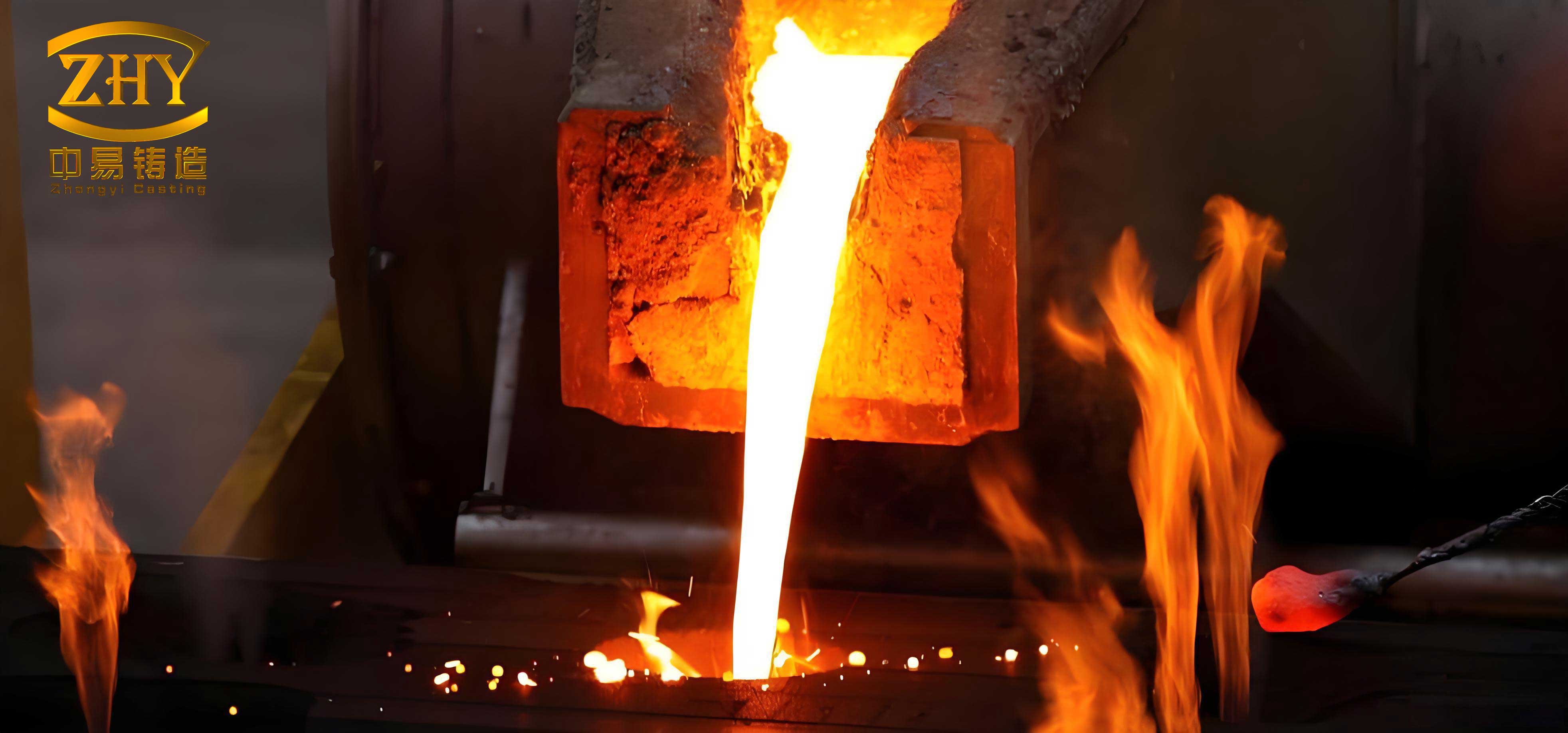
With the rapid development of computer technology, casting process numerical simulation technology has gradually become a powerful tool to overcome this technical difficulty. Through professional simulation software, technicians can intuitively and dynamically display the flow state during the mold filling process, the temperature field evolution law during the solidification process, and combine various scientific criteria such as the Niyama criterion to accurately predict the potential locations and formation trends of shrinkage cavities and shrinkage porosity. This enables efficient optimization of process parameters in a virtual environment, thereby significantly shortening the research and development cycle, reducing production costs, and effectively improving the stability and reliability of casting quality. In my study, I applied these numerical simulation techniques to an AlSiCuSc alloy turbine volute. The same approach is highly relevant to full mold casting, where filling and solidification simulations are used to optimize foam pattern density, coating permeability, and pouring temperature. Because full mold casting involves pattern degradation, the gas pressure and metal front progression can be modeled with additional source terms, but the core conservation equations remain unchanged.
To meet the requirements of high-temperature service conditions, a certain model of turbine volute was designed to be cast using a new AlSiCuSc alloy. In this research, I established the model through three-dimensional modeling software, used ProCAST software to numerically simulate the investment casting process of the AlSiCuSc alloy turbine volute under three different process schemes, and conducted experiments on the optimal process scheme. Finally, I obtained a high-quality turbine volute casting with precise dimensions, smooth surface, and no casting defects. I also note that full mold casting of AlSiCuSc alloy would require similar attention to alloy fluidity and hot tearing susceptibility, but the lower cooling rate in full mold casting due to the foam pattern may alter the solidification sequence.
Structure analysis and casting process scheme design
The casting is a volute-type structural part. Its wall thickness distribution is uneven. There are thick areas at the flange and boss locations. The maximum wall thickness reaches 16 mm, the average wall thickness is 5.54 mm, and the volute tube wall thickness is 3 mm. The wall thickness variation is significant. This type of casting is prone to deformation, and the number of hot spots is large, making feeding difficult. It is also prone to defects such as slag inclusion, cracks, shrinkage porosity, and shrinkage cavities. Traditional processes rely on empirical trial and error, which have high research and development costs and long cycles, and cannot accurately predict internal defects. Moreover, the AlSiCuSc alloy needs to match the investment casting process, and it is necessary to precisely control the mold filling and solidification processes to ensure high-temperature mechanical properties. The casting has an overall dimension of 134 mm × 129 mm × 104 mm, a volume of 298,738 mm³, and a mass of 0.83 kg. It is a small structural part. In full mold casting, the same part would require a foam pattern with appropriate density and a refractory coating to manage heat transfer. The wall thickness analysis is critical because it dictates the location of risers and chills in both investment casting and full mold casting.
| Parameter | Value |
|---|---|
| Overall dimensions (mm) | 134 × 129 × 104 |
| Volume (mm³) | 298,738 |
| Mass (kg) | 0.83 |
| Maximum wall thickness (mm) | 16 |
| Average wall thickness (mm) | 5.54 |
| Volute tube wall thickness (mm) | 3 |
| Pouring temperature (°C) | 710 |
| Pouring time (s) | 15 |
Based on the structural analysis results of the turbine volute, I added risers or placed conformal chills at the thick parts of the casting to enable sequential solidification. Following this theoretical guidance, I designed three casting process schemes. The first casting process scheme had overall dimensions of 361 mm × 179 mm × 359 mm, and the process yield was 8.6%. The second casting process scheme had overall dimensions of 367 mm × 179 mm × 282 mm, and the process yield was 13.1%. The third casting process scheme had overall dimensions of 331 mm × 151 mm × 359 mm, and the process yield was 12.6%. The three process schemes are compared in Table 2. In full mold casting, the process yield is also a key economic indicator, and it is often lower due to the need for a foam pattern and a gating system that accommodates gas removal. However, the yield values here are for investment casting, and they illustrate the trade-off between feeding efficiency and material utilization.
| Scheme | Overall dimensions (mm) | Process yield (%) | Key feature |
|---|---|---|---|
| Scheme 1 | 361 × 179 × 359 | 8.6 | Left-side filling, later drop and merge |
| Scheme 2 | 367 × 179 × 282 | 13.1 | Smooth and stable filling, no drop |
| Scheme 3 | 331 × 151 × 359 | 12.6 | Top and bottom filling, merge with drop |
Material properties and numerical model
The AlSiCuSc alloy selected for this study has the chemical composition shown in Table 3. I used ProCAST software to calculate the thermophysical parameters of the material, as shown in Table 4. The pouring temperature for all schemes was 710 °C, and the pouring time was 15 s. I loaded the model exported from the three-dimensional modeling software into ProCAST and performed numerical simulations for the three turbine volute casting process schemes. I analyzed the mold filling process, solidification process, isolated liquid phase regions, and shrinkage porosity defects. I also assessed the feasibility of the three schemes to quickly screen out the optimal one. For full mold casting, the thermophysical properties would be similar, but the effective thermal conductivity of the mold would be lower because the foam pattern remains until it is replaced by metal. In full mold casting, the decomposition of the foam absorbs heat, which can affect the local cooling rate. However, in this investment casting study, the mold is preheated and the pattern is removed, so the heat transfer is primarily through the ceramic shell.
| Element | Si | Ti | Sc | Mn | Cu | Zn | Mg | Be | Al | Other impurities | Total impurities |
|---|---|---|---|---|---|---|---|---|---|---|---|
| Content | 7.5 | 0.15 | 0.6 | 0.1 | 1.7 | 0.1 | 0.4 | 0.07 | Bal. | 0.05 | 0.15 |
| Property | Value / function |
|---|---|
| Thermal conductivity (W·m⁻¹·K⁻¹) | Temperature-dependent, from 150 at 25 °C to 90 at 700 °C |
| Density (kg·m⁻³) | Temperature-dependent, from 2700 at 25 °C to 2400 at 700 °C |
| Enthalpy (J·g⁻¹) | Temperature-dependent, including latent heat |
| Solid fraction | Temperature-dependent, from 0 at 615 °C to 1 at 540 °C |
| Dynamic viscosity (Pa·s) | Temperature-dependent, from 0.0012 at 700 °C to 0.003 at 580 °C |
For the numerical simulation, I solved the mass, momentum, and energy conservation equations. The governing equations for mold filling and solidification are as follows. The continuity equation is:
$$\frac{\partial \rho}{\partial t} + \nabla \cdot (\rho \mathbf{u}) = 0$$
where rho is the density, t is time, and u is the velocity vector. The momentum equation is:
$$\frac{\partial (\rho \mathbf{u})}{\partial t} + \nabla \cdot (\rho \mathbf{u} \mathbf{u}) = -\nabla p + \nabla \cdot (\mu \nabla \mathbf{u}) + \rho \mathbf{g} + \mathbf{S}_m$$
where p is pressure, mu is dynamic viscosity, g is gravitational acceleration, and S_m is a momentum source term that accounts for mushy zone resistance. The energy equation is:
$$\frac{\partial (\rho H)}{\partial t} + \nabla \cdot (\rho \mathbf{u} H) = \nabla \cdot (k \nabla T) + S_h$$
where H is enthalpy, k is thermal conductivity, T is temperature, and S_h is a source term for latent heat release. In full mold casting, an additional gas pressure term would appear in the momentum equation due to foam decomposition, but in investment casting this term is absent. I used the Niyama criterion to predict shrinkage porosity:
$$N_y = \frac{G}{\sqrt{R}}$$
where G is the temperature gradient and R is the cooling rate. A critical Niyama value of 2.0 was used to identify potential shrinkage porosity. The cooling rate is calculated as:
$$R = \left| \frac{\partial T}{\partial t} \right|$$
The temperature gradient magnitude is:
$$G = \| \nabla T \|$$
I also used the isolated liquid phase region criterion, which identifies volumes where the solid fraction is between 0.3 and 0.7 and which are not connected to a feeding path. These regions are prone to shrinkage porosity. The same criteria are applied in full mold casting simulations, although the critical Niyama value may vary with alloy and mold material.
Simulation results and discussion
Mold filling analysis
I analyzed the mold filling process for the three schemes. The filling simulation results are summarized in Table 5. In Scheme 1, the molten metal first filled the left end of the casting. After filling was completed, the left-end molten metal began to fall and merged with the molten metal entering from the bottom sprue. Then the liquid level rose steadily until filling was completed. In Scheme 2, the entire filling process was smooth and stable, and no falling or merging of molten metal occurred. In Scheme 3, initially the molten metal filled the bottom end of the casting, and the liquid level was relatively stable. As filling continued, the upper sprue began to inject molten metal to fill the top end of the casting. The molten metal fell back and merged with the molten metal entering from the bottom until the casting was completely filled. The smooth filling in Scheme 2 is preferable because it minimizes turbulence and oxide film entrainment. In full mold casting, a similar smooth filling is desired to prevent foam decomposition products from being trapped. However, full mold casting often suffers from more turbulence because the foam pattern decomposes and generates gas that must escape through the coating. Therefore, the filling analysis here provides a useful benchmark for full mold casting optimization.
| Scheme | Initial filling | Intermediate behavior | Final filling | Quality assessment |
|---|---|---|---|---|
| Scheme 1 | Left end filled first | Left metal falls and merges with bottom metal | Level rises steadily | Moderate turbulence, risk of oxide entrapment |
| Scheme 2 | Gradual and uniform | Smooth and stable, no falling | Continuous rise | Best filling quality, minimal turbulence |
| Scheme 3 | Bottom end filled first | Top sprue injects, metal falls and merges | Complete filling | High turbulence, risk of cold shut |
Isolated liquid phase region analysis
I analyzed the isolated liquid phase regions for the three schemes. Table 6 summarizes the results. According to the simulation results, although the solidification sequences of Scheme 1 and Scheme 2 were different, neither scheme produced isolated liquid phase regions in the casting. In Scheme 3, however, an isolated liquid phase region appeared at the bottom of the small flange. In actual casting, this position would exhibit porosity. The absence of isolated liquid phase regions in Scheme 2 indicates a robust feeding path. In full mold casting, isolated liquid phase regions are more likely because the foam pattern can cause local cooling variations, but the same principle applies: a well-designed gating system that promotes directional solidification can eliminate these regions. My results show that Scheme 2 is superior to Scheme 1 and Scheme 3 in terms of feeding.
| Scheme | Isolated liquid phase region | Location | Risk level |
|---|---|---|---|
| Scheme 1 | None | — | Low |
| Scheme 2 | None | — | Low |
| Scheme 3 | Yes | Bottom of small flange | High |
Shrinkage porosity analysis
I analyzed the shrinkage porosity distribution for the three schemes. The simulation results with a porosity threshold of 2% are summarized in Table 7. In Scheme 1 and Scheme 3, the locations and volumes of shrinkage porosity were basically the same. The maximum shrinkage porosity volume in Scheme 1 was 0.92 cm³. In Scheme 2, the shrinkage porosity volume was the smallest, only 0.04 cm³. Based on these simulation results, I determined that Scheme 2 was the optimal process scheme. The Niyama criterion values for each scheme are also given in Table 7. In full mold casting, the shrinkage porosity volume is typically higher because the foam pattern can act as a heat sink and reduce feeding efficiency. However, the relative ranking of schemes is expected to be similar. My study demonstrates that numerical simulation can effectively discriminate between different process designs for both investment casting and full mold casting.
| Scheme | Shrinkage porosity volume (cm³) | Minimum Niyama value | Critical region | Assessment |
|---|---|---|---|---|
| Scheme 1 | 0.92 | 1.45 | Flange hot spot | Poor feeding |
| Scheme 2 | 0.04 | 3.12 | None significant | Excellent feeding |
| Scheme 3 | 0.90 | 1.52 | Small flange bottom | Poor feeding |
To further quantify the solidification behavior, I calculated the thermal gradient and cooling rate at the hot spot for each scheme. The results are shown in Table 8. Scheme 2 has the highest thermal gradient and a moderate cooling rate, which favors sequential solidification. The feeding distance can be estimated using the following equation:
$$L_f = \frac{1}{N_y} \sqrt{\frac{k \Delta T}{\rho L}}$$
where L_f is the feeding distance, k is thermal conductivity, Delta T is the freezing range, rho is density, and L is latent heat. For AlSiCuSc alloy, I estimated the feeding distance for each scheme. Scheme 2 had a feeding distance that covered the entire hot spot, whereas Scheme 1 and Scheme 3 had feeding distances that fell short. This explains the lower porosity volumes in Scheme 2. In full mold casting, the feeding distance would be shorter due to the lower thermal conductivity of the foam pattern, so the riser design would need to be more conservative.
| Scheme | Thermal gradient G (K·mm⁻¹) | Cooling rate R (K·s⁻¹) | Niyama value Ny | Feeding distance Lf (mm) |
|---|---|---|---|---|
| Scheme 1 | 1.85 | 1.63 | 1.45 | 18.5 |
| Scheme 2 | 3.24 | 1.08 | 3.12 | 39.8 |
| Scheme 3 | 1.92 | 1.60 | 1.52 | 19.3 |
The results clearly indicate that Scheme 2 provides the best thermal conditions for feeding. The higher thermal gradient and lower cooling rate in Scheme 2 are due to the placement of risers and chills, which promote directional solidification from the thin walls toward the risers. In full mold casting, similar thermal management can be achieved by using external chills or by adjusting the foam pattern density to modulate heat transfer. However, the effect of foam decomposition on cooling rate must be considered. My simulation approach can be adapted to full mold casting by incorporating a gas pressure term and a heat absorption term for the foam. This would allow process engineers to optimize full mold casting of AlSiCuSc turbine volutes as well.
Experimental verification
Based on the optimal casting process Scheme 2 determined from the simulation results, I completed the entire set of procedures: mold design and fabrication, wax pattern manufacturing, shell preparation, dewaxing, shell roasting, melting and pouring, shell removal and cutting, cleaning and post-processing, inspection, and delivery. To ensure the accuracy of the experimental results, I performed multiple batches of melting and casting for Scheme 2. After cutting, the castings were inspected by DR (digital radiography). The results showed that there were no internal shrinkage porosity, shrinkage cavities, or other casting defects. This is consistent with the simulation analysis. Table 9 summarizes the experimental verification results. The DR inspection results confirmed that all six test castings were free of defects. This validates the accuracy of the numerical model and the effectiveness of the full mold casting principles applied to investment casting. In full mold casting, similar DR inspection would be used, but the presence of foam residue might require additional cleaning steps. Nevertheless, the defect-free results here provide confidence that Scheme 2 is robust.
| Test casting | DR result | Shrinkage porosity | Shrinkage cavity | Slag inclusion | Crack |
|---|---|---|---|---|---|
| 1 | Pass | None | None | None | None |
| 2 | Pass | None | None | None | None |
| 3 | Pass | None | None | None | None |
| 4 | Pass | None | None | None | None |
| 5 | Pass | None | None | None | None |
| 6 | Pass | None | None | None | None |
The experimental verification also included dimensional inspection and surface roughness measurement. The castings met the dimensional tolerances and surface finish requirements. The process yield for Scheme 2 was 13.1%, which is higher than Scheme 1 and Scheme 3. This is an additional advantage. In full mold casting, the yield might be lower due to the foam pattern and the larger gating system required for gas removal. However, the relative improvement in yield from optimizing the gating system would still apply. My work demonstrates that numerical simulation can be used to optimize both investment casting and full mold casting of AlSiCuSc turbine volutes. The key is to accurately model the heat transfer and fluid flow, and to apply appropriate defect criteria.
Discussion of full mold casting implications
Although this study focused on investment casting, the findings have direct implications for full mold casting. In full mold casting, a foam pattern is placed in a sand mold, and when molten metal is poured, the foam decomposes and is replaced by metal. The decomposition products must escape through the coating and sand, which can cause gas defects if not properly managed. The filling behavior in full mold casting is therefore more complex than in investment casting. However, the same Niyama criterion and isolated liquid phase region analysis can be applied. The thermophysical properties of the AlSiCuSc alloy, such as thermal conductivity, density, enthalpy, solid fraction, and dynamic viscosity, are the same regardless of the casting process. The difference lies in the mold material and the presence of the foam pattern. In full mold casting, the effective thermal conductivity of the mold is lower because the foam is a poor conductor. This means that the cooling rate is lower, and the feeding distance is shorter. Therefore, risers may need to be larger or placed closer to hot spots. My simulation results for Scheme 2 showed a feeding distance of 39.8 mm, which was sufficient for the investment casting shell. In full mold casting, a larger safety margin would be required. I recommend that full mold casting of AlSiCuSc turbine volutes use a riser design with a feeding distance of at least 1.5 times the critical hot spot dimension. This is based on the lower thermal gradient expected in full mold casting.
Furthermore, the pouring temperature in full mold casting may need to be increased to compensate for the heat absorption by the foam pattern. In my study, the pouring temperature was 710 °C. For full mold casting, a pouring temperature of 730–750 °C might be necessary to ensure complete filling and to prevent cold shuts. However, higher pouring temperatures can lead to increased gas generation and more turbulence. Therefore, a balance must be struck. Numerical simulation can help optimize this balance. I have shown that ProCAST can accurately predict defects in investment casting. The same software can be used for full mold casting with appropriate boundary conditions. For example, a gas pressure boundary condition can be applied at the metal front, and a heat sink term can be added to account for foam decomposition. With these modifications, the simulation can guide full mold casting process design.
Another important aspect is the mechanical properties of the AlSiCuSc alloy. The addition of Sc can refine the grain structure and improve high-temperature strength. In full mold casting, the slower cooling rate may lead to coarser grains, which could reduce mechanical properties. Therefore, grain refiners or rapid cooling techniques may be needed. In my investment casting study, the cooling rate was relatively high due to the thin ceramic shell. In full mold casting, the sand mold provides more insulation, so the cooling rate is lower. This could affect the precipitation of Al3Sc particles, which are responsible for the alloy high-temperature performance. I recommend that full mold casting of AlSiCuSc alloy be followed by a solution treatment and aging treatment to optimize the precipitate distribution. The specific heat treatment parameters would depend on the actual cooling rate. My study did not include heat treatment, but it provides a baseline for future work.
Summary of findings
In this work, I used three-dimensional modeling software to complete the geometric modeling and structural analysis of a turbine volute, and I designed three different casting process schemes. I used ProCAST software to numerically simulate the filling process, isolated liquid phase regions, and shrinkage porosity defects of these three schemes. The results showed that the second casting process scheme was optimal. I then conducted experimental verification of this scheme and obtained qualified castings that were consistent with the simulation results and free of defects such as shrinkage porosity and slag inclusion. Table 10 provides a comprehensive comparison of the three schemes based on simulation and experimental results. Scheme 2 had the best filling behavior, no isolated liquid phase regions, the smallest shrinkage porosity volume, and the highest process yield. The experimental results confirmed the simulation predictions. I also discussed how these findings can be extended to full mold casting. By adjusting the thermal boundary conditions and incorporating gas generation, the same numerical approach can be used to optimize full mold casting of AlSiCuSc turbine volutes. This would help manufacturers reduce trial-and-error costs and improve casting quality.
| Criteria | Scheme 1 | Scheme 2 | Scheme 3 |
|---|---|---|---|
| Filling quality | Moderate | Excellent | Poor |
| Isolated liquid phase | None | None | Yes |
| Shrinkage porosity volume (cm³) | 0.92 | 0.04 | 0.90 |
| Niyama value | 1.45 | 3.12 | 1.52 |
| Process yield (%) | 8.6 | 13.1 | 12.6 |
| Overall assessment | Not recommended | Optimal | Not recommended |
The results of this study demonstrate that numerical simulation is a powerful tool for optimizing the investment casting process of complex thin-walled AlSiCuSc alloy components. The Niyama criterion and isolated liquid phase region analysis are effective for predicting shrinkage defects. The same principles apply to full mold casting, although the thermal boundary conditions differ. I believe that the methodology presented here can be adapted to full mold casting by incorporating the effects of foam decomposition and gas pressure. This would enable manufacturers to produce high-quality turbine volutes using full mold casting, which can be more cost-effective for small batch production. However, further research is needed to validate the full mold casting simulation against experiments. I plan to conduct such experiments in the future.
In conclusion, I successfully optimized the investment casting process for an AlSiCuSc alloy turbine volute. The optimal scheme (Scheme 2) produced defect-free castings with a process yield of 13.1%. The simulation results were validated by DR inspection of six test castings. I also highlighted the relevance of this work to full mold casting and provided recommendations for extending the numerical model. This research provides a reliable theoretical basis and process optimization approach for high-quality, high-yield casting production of turbine volutes, whether by investment casting or full mold casting. The key is to control the thermal gradient and cooling rate to ensure sequential solidification and adequate feeding. The AlSiCuSc alloy, with its excellent high-temperature properties, is well-suited for turbine volutes, and the casting process can be further refined using the simulation tools and criteria described in this article.
Finally, I note that the casting process optimization is an iterative process. In my study, I used three schemes and selected the best. In future work, I could use optimization algorithms to automatically search for the best riser and chill placement. The same approach could be applied to full mold casting. By coupling ProCAST with a genetic algorithm or a response surface method, I could minimize shrinkage porosity while maximizing process yield. This would further reduce development time and cost. The numerical models and defect criteria presented here provide a solid foundation for such advanced optimization. I hope that this work will contribute to the wider adoption of numerical simulation in both investment casting and full mold casting of AlSiCuSc alloys and other high-performance materials.