
In this study, I focused on integrating 3D printing technology with traditional sand mold casting to manufacture complex parts, particularly an automotive engine cylinder block made of ZL101A aluminum alloy. Traditional sand mold casting has long been a cornerstone of metal component production, but it suffers from high sensitivity to part complexity, long lead times, and costly mold fabrication. By contrast, 3D printed sand molds enable rapid, mold-free production of intricate geometries, allowing me to combine the flexibility of additive manufacturing with the excellent mechanical properties and low cost of sand mold casting. My research systematically investigated the effects of printing parameters, pouring parameters, and mold preheating on the microstructure and mechanical properties of aluminum alloy castings. I then designed a conformal gating system for the cylinder block, validated it using simulation software, and finally produced a functional engine cylinder block via 3D printed sand mold casting. The results demonstrate that this hybrid approach significantly shortens production cycles, reduces defects, and achieves performance that meets automotive standards.
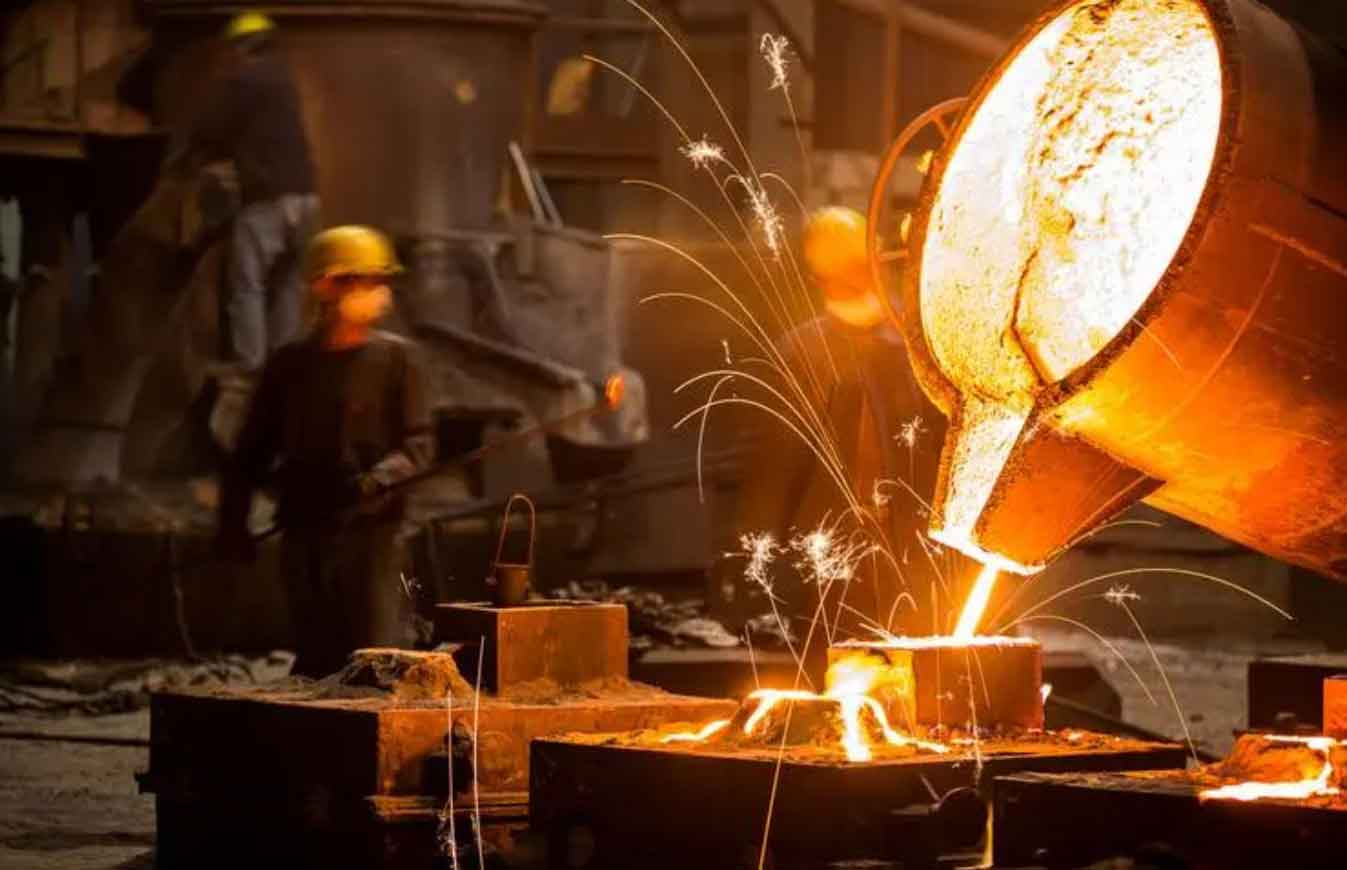
Introduction to sand mold casting and 3D printing
Sand mold casting is a versatile process in which molten metal is poured into a cavity formed by compacted sand. It is widely used for large and complex parts because of its low cost, good dimensional tolerance, and ability to cast almost any alloy. However, conventional sand mold casting requires pattern making, core assembly, and considerable manual labor, which makes it inefficient for rapid prototyping and low-volume production. The complexity of a part often dictates the number of molds and cores needed, increasing both cost and lead time. To overcome these limitations, I adopted binder jetting 3D printing to create sand molds directly from CAD data. This technology eliminates the need for physical patterns and allows the production of molds with conformal cooling channels, integrated gating systems, and complex internal cavities. The 3D printed sand mold casting process combines the design freedom of additive manufacturing with the material flexibility of conventional casting.
In my experiments, I used a PCM-800 3D sand printer with a maximum build size of 800 × 750 × 500 mm, a layer thickness adjustable from 0.2 to 0.5 mm, and a print speed of 20–25 s per layer. The sand material was high-white silica sand with a particle size distribution mainly between 0.05 and 0.38 mm. The binder was a furan resin (2.36 wt.% of sand) and the catalyst was a sulfonic acid-based hardener (0.4 wt.%). After printing, the molds were cured for 60 minutes, then dried at 150 °C for 2 hours to remove moisture and excess binder. This drying step is critical because it reduces gas evolution during pouring and prevents defects such as porosity and blowholes.
Materials and experimental methods
The target alloy was ZL101A (AlSi7Mg0.3), a widely used cast aluminum alloy for automotive and aerospace components. Its chemical composition is listed in Table 1. I added a small amount of Sr as a modifier to improve the eutectic silicon morphology and enhance fluidity. The melt was prepared in an induction furnace, degassed with Ar gas, and refined using a rotary impeller. After refining, the melt was held at the pouring temperature and then poured into the 3D printed sand molds under gravity. For tensile testing, I cast cylindrical specimens with a 30 mm wall thickness according to GB/T 1173-2013. T6 heat treatment consisted of solution treatment at 530 °C for 8–10 hours, water quenching at 70 °C, and artificial aging at 180 °C for 6–8 hours. Microstructural analysis was performed using optical microscopy, scanning electron microscopy (SEM), and energy-dispersive X-ray spectroscopy (EDS). Density was measured by Archimedes’ principle. Tensile tests were conducted on an electronic universal testing machine at a crosshead speed of 10 mm/min.
| Element | Si | Mg | Ti | Sr | Fe | Zn | V | Al |
|---|---|---|---|---|---|---|---|---|
| wt.% | 7.223 | 0.322 | 0.106 | 0.041 | 0.109 | 0.017 | 0.015 | Balance |
Effect of mold type on casting microstructure and properties
I first compared three mold types: traditional green sand mold, 3D printed sand mold, and permanent metal mold. All castings were produced with a pouring temperature of 720 °C and no mold preheating. The as-cast microstructure of the traditional sand mold casting showed a secondary dendrite arm spacing (SDAS) of 63.05 μm, with fine eutectic Si and some gas pores. The 3D printed sand mold casting exhibited a slightly coarser SDAS of 84.08 μm, but fewer inclusions and pores. The metal mold casting had the finest SDAS of 25.94 μm due to rapid cooling. The tensile properties are summarized in Table 2. The 3D printed sand mold casting achieved a tensile strength of 131 MPa and elongation of 2.2%, which was slightly better than the traditional sand mold casting (127 MPa and 1.9%). The metal mold casting reached 184 MPa and 3.4%. Fracture surface analysis revealed that the 3D printed sand mold casting exhibited a mixed cleavage–dimple fracture mode, indicating better ductility than the traditional sand mold casting. The density of the 3D printed sand mold casting was 2.6300 g/cm³, slightly higher than the traditional sand mold casting (2.6260 g/cm³) but lower than the metal mold casting (2.6753 g/cm³). These results confirm that 3D printed sand mold casting can match or slightly exceed the quality of traditional sand mold casting.
| Mold type | Tensile strength (MPa) | Elongation (%) | Density (g/cm³) |
|---|---|---|---|
| Traditional sand mold | 127 | 1.9 | 2.6260 |
| 3D printed sand mold | 131 | 2.2 | 2.6300 |
| Metal mold | 184 | 3.4 | 2.6753 |
Influence of mold preheating and pouring temperature
I investigated the effect of mold preheating on the microstructure and mechanical properties of the castings. The 3D printed sand molds were dried at 150 °C for 2 hours and then either left at room temperature or preheated to 100, 150, and 200 °C before pouring at 720 °C. The results showed that increasing the mold preheating temperature coarsened the microstructure. The SDAS increased from 57.58 μm at room temperature to 90.72 μm at 200 °C, a 36.5% increase. The tensile strength and elongation decreased accordingly, as shown in Table 3. Therefore, for castings without special requirements, I recommend pouring directly after drying and cooling to room temperature. This avoids excessive grain growth and reduces gas defects because the dried mold has minimal residual moisture and binder.
| Mold preheating temperature (°C) | SDAS (μm) | Tensile strength (MPa) | Elongation (%) |
|---|---|---|---|
| Room temperature (no preheat) | 57.58 | 218 | 0.4 |
| 100 | 66.32 | 215 | 0.4 |
| 150 | 75.45 | 210 | 0.3 |
| 200 | 90.72 | 205 | 0.3 |
Next, I studied the effect of pouring temperature on the same 3D printed sand molds (dried at 150 °C, cooled to room temperature). The pouring temperatures were 700, 710, 720, and 740 °C. The optimal pouring temperature was 720 °C, which produced fine, uniformly distributed eutectic Si particles and the smallest SDAS of 70.69 μm. At 700 and 710 °C, the eutectic Si remained coarse and plate-like due to insufficient modification. At 740 °C, the eutectic Si coarsened, and second-phase particles such as β-Fe, α-Fe, and π-Fe precipitated, which degraded the mechanical properties. Table 4 shows the mechanical properties after T6 heat treatment. The best combination was obtained at 720 °C: tensile strength 229 MPa and elongation 0.5%. At 740 °C, the tensile strength dropped to 215 MPa and elongation to 0.3%. The fracture surfaces exhibited brittle cleavage with secondary cracks and Fe-rich phases, confirming the detrimental effect of higher pouring temperatures.
| Pouring temperature (°C) | SDAS (μm) | Tensile strength (MPa) | Elongation (%) |
|---|---|---|---|
| 700 | 75.21 | 210 | 0.3 |
| 710 | 72.45 | 218 | 0.4 |
| 720 | 70.69 | 229 | 0.5 |
| 740 | 78.34 | 215 | 0.3 |
Effect of printing layer thickness
The printing layer thickness determines the amount of binder and the packing density of the sand mold. I compared two layer thicknesses: 0.4 mm and 0.5 mm. The 0.5 mm layer thickness produced a sand mold with lower binder content, which reduced gas evolution during pouring. The casting produced with the 0.5 mm layer thickness had a density of 2.6503 g/cm³, a tensile strength of 229 MPa, and an elongation of 0.5%, whereas the 0.4 mm layer thickness gave 2.6454 g/cm³, 218 MPa, and 0.4%. The microstructure of the 0.5 mm sample showed more uniform dendrites and fewer pores. The 0.4 mm sample had a higher binder content, leading to more gas defects and incomplete modification. Therefore, I selected 0.5 mm as the optimal layer thickness for subsequent work.
| Layer thickness (mm) | Density (g/cm³) | Tensile strength (MPa) | Elongation (%) |
|---|---|---|---|
| 0.4 | 2.6454 | 218 | 0.4 |
| 0.5 | 2.6503 | 229 | 0.5 |
Design and simulation of the gating system for the engine cylinder block
The target part was a three-cylinder inline engine cylinder block with overall dimensions of approximately 500 × 500 × 500 mm and wall thicknesses ranging from 2 to 40 mm. To reduce weight and improve wear resistance, three cast iron cylinder liners with an outer diameter of 87.6 mm and a wall thickness of 6 mm were embedded in the aluminum alloy. The liners had to be bonded tightly with the aluminum alloy, with a minimum post-casting diameter of 83 mm and no gaps. I designed a conformal gating system that took advantage of the 3D printing freedom. The gating system consisted of a sprue, two horizontal runners (upper and lower), and multiple ingates. The cross-sectional area ratio of sprue:runner:ingate was designed as 1:2:4, following the large-orifice discharge theory. The sprue diameter was 60 mm, and the static pressure head was 400 mm. I used a stepped pouring system to ensure smooth filling and sequential solidification.
To validate the design, I used ProCAST simulation software. The mesh was generated with tetrahedral elements: 4 mm edge length for the casting and gating system, and 20 mm for the sand mold shell. The total number of volume meshes was 11,717,789. The material properties for ZL101A and the furan sand mold were taken from the software database. The interface heat transfer coefficients were set as follows: casting–sand mold 500 W/(m²·°C), casting–cast iron 2000 W/(m²·°C), cast iron–sand mold 500 W/(m²·°C). The pouring temperature was 730 °C, and the pouring speed was 3 kg/s. The cylinder liners were preheated to 400 °C using built-in heating rods to ensure proper fusion.
The governing equations for the filling and solidification processes are as follows. The mass conservation equation for incompressible flow is:
$$\frac{\partial u}{\partial x}+\frac{\partial v}{\partial y}+\frac{\partial w}{\partial z}=0$$
The momentum conservation equations (Navier–Stokes) in three directions are:
$$\frac{\partial u}{\partial t}+u\frac{\partial u}{\partial x}+v\frac{\partial u}{\partial y}+w\frac{\partial u}{\partial z}=-\frac{1}{\rho}\frac{\partial p}{\partial x}+g_x+\gamma\left(\frac{\partial^2 u}{\partial x^2}+\frac{\partial^2 u}{\partial y^2}+\frac{\partial^2 u}{\partial z^2}\right)$$
$$\frac{\partial v}{\partial t}+u\frac{\partial v}{\partial x}+v\frac{\partial v}{\partial y}+w\frac{\partial v}{\partial z}=-\frac{1}{\rho}\frac{\partial p}{\partial y}+g_y+\gamma\left(\frac{\partial^2 v}{\partial x^2}+\frac{\partial^2 v}{\partial y^2}+\frac{\partial^2 v}{\partial z^2}\right)$$
$$\frac{\partial w}{\partial t}+u\frac{\partial w}{\partial x}+v\frac{\partial w}{\partial y}+w\frac{\partial w}{\partial z}=-\frac{1}{\rho}\frac{\partial p}{\partial z}+g_z+\gamma\left(\frac{\partial^2 w}{\partial x^2}+\frac{\partial^2 w}{\partial y^2}+\frac{\partial^2 w}{\partial z^2}\right)$$
The energy conservation equation is:
$$\frac{\partial T}{\partial t}+u\frac{\partial T}{\partial x}+v\frac{\partial T}{\partial y}+w\frac{\partial T}{\partial z}=\frac{\lambda}{\rho c}\left(\frac{\partial^2 T}{\partial x^2}+\frac{\partial^2 T}{\partial y^2}+\frac{\partial^2 T}{\partial z^2}\right)+\frac{S}{\rho c}$$
For solidification, the heat conduction equation is:
$$\rho c_p \frac{\partial T}{\partial t}=\frac{\partial}{\partial x}\left(\lambda \frac{\partial T}{\partial x}\right)+\frac{\partial}{\partial y}\left(\lambda \frac{\partial T}{\partial y}\right)+\frac{\partial}{\partial z}\left(\lambda \frac{\partial T}{\partial z}\right)+Q$$
where the source term \(Q\) accounts for latent heat release:
$$Q=\rho L \frac{\partial f_s}{\partial T}$$
Convective heat transfer is described by Newton’s law of cooling:
$$q=a(T_f-T_w)$$
Radiative heat transfer follows the Stefan–Boltzmann law:
$$q=\varepsilon \sigma_0 T_s^4$$
Latent heat is treated uniformly over the solidification interval:
$$\frac{\partial L}{\partial t}\Delta t=-\rho L \frac{\Delta T}{T_L-T_S}$$
For shrinkage porosity prediction, I used the Niyama criterion:
$$N=\sqrt{\frac{G}{R}}$$
where \(G\) is the temperature gradient and \(R\) is the cooling rate. A lower \(N\) value indicates a higher probability of shrinkage defects.
I evaluated three different pouring orientations: A (upright), B (side), and C (inverted). The details are given in Table 5. The simulation results showed that orientation C provided the best filling and solidification behavior. The filling time for the main body was 10.67 s, and the total defect volume was only 0.899 cc. Orientation A had a defect volume of 0.913 cc, and B had 1.043 cc with a large shrinkage cavity near the assembly holes. Orientation C also ensured proper fusion between the aluminum alloy and the cast iron liners because the liners were placed at the bottom and preheated. The solidification time for the main body was 440 s, and no large isolated liquid regions formed. The overall solidification efficiency was high, with only 82.8% of the casting solidified when the isolated liquid regions disappeared, allowing effective feeding from the risers.
| Process scheme | Pouring orientation | Total pouring mass (kg) | Yield (%) | Defect volume (cc) |
|---|---|---|---|---|
| A | Upright | 46.99 | 38.52 | 0.913 |
| B | Side | 40.86 | 44.30 | 1.043 |
| C | Inverted | 48.17 | 37.58 | 0.899 |
Rapid casting of the engine cylinder block using 3D printed sand molds
Based on the optimized parameters, I produced the engine cylinder block using 3D printed sand mold casting. The sand mold was printed with a layer thickness of 0.5 mm, a printing speed of 25 s/layer, and a single-pass printing strategy. The total printing time was 10 hours. After printing, the mold was cleaned, coated with a FAS 201 foundry coating, and dried at 150 °C for 2 hours. Then, the chills, filters, cylinder liners, and heating rods were assembled. The mold was closed and sealed. The ZL101A alloy was melted, degassed, and poured at 730 °C. After pouring, the casting was allowed to cool in the mold for 10 minutes, then shaken out, water-cooled, and subjected to T6 heat treatment. The entire production cycle from design to finished casting took only 3–4 days, compared with weeks or months for traditional sand mold casting with pattern making.
The casting was inspected using X-ray radiography, pressure leak testing, and metallographic analysis. X-ray inspection showed no significant internal defects, and the cylinder liners were well bonded with the aluminum alloy. The pressure leak test at 0.3 MPa for 5–10 minutes showed no bubbles or leakage. The average penetration depth between the liners and the aluminum alloy was 2–3 mm, and the post-casting liner diameter was 85.67 mm, exceeding the minimum requirement of 83 mm. The microstructure of the cylinder block was fine and uniform, with no obvious segregation. The tensile properties after T6 heat treatment are given in Table 6. The measured tensile strength was 278 MPa, elongation 2.3%, and Brinell hardness 97 HB, all exceeding the standard requirements for ZL101A (tensile strength > 220 MPa, elongation > 2.0%, hardness > 80 HB). These results confirm that the 3D printed sand mold casting process is capable of producing high-quality complex engine components.
| Property | Standard value (ZL101A, T6) | Measured value |
|---|---|---|
| Tensile strength (MPa) | > 220 | 278 |
| Elongation (%) | > 2.0 | 2.3 |
| Brinell hardness (HB) | > 80 | 97 |
Discussion of process parameters and their influence on sand mold casting
The quality of sand mold casting depends on a complex interplay of mold properties, filling behavior, and solidification conditions. In my experiments, I found that the printing layer thickness has a direct effect on the binder content and gas evolution. A thicker layer (0.5 mm) reduces the number of printed layers, thus lowering the total binder amount, which in turn reduces gas defects. However, if the layer is too thick, the dimensional accuracy and surface finish may deteriorate. I also observed that mold preheating is generally unnecessary for 3D printed sand molds because the drying step already removes moisture and volatiles. Preheating only slows down cooling, coarsens the microstructure, and can cause sand erosion. The optimal pouring temperature for ZL101A in 3D printed sand molds is around 720 °C. Lower temperatures lead to incomplete filling and poor modification, while higher temperatures cause oxidation, gas absorption, and precipitation of detrimental iron-rich phases.
The gating system design is another critical factor. Traditional sand mold casting often uses simple gating systems that are easy to mold but not optimized for fluid flow. With 3D printing, I could design a conformal gating system that follows the contour of the casting and distributes the melt evenly. The use of two horizontal runners ensures that the melt fills the thin walls rapidly while the thick sections are fed by the risers. The simulation results confirmed that the inverted orientation (C) provides the best balance between filling efficiency and solidification consistency. The lower defect volume and shorter filling time demonstrate the superiority of the conformal design.
In terms of mechanical properties, the 3D printed sand mold castings consistently outperformed traditional sand mold castings in terms of density and elongation, although the tensile strength was similar. The improved density is attributed to fewer gas defects and better mold filling. The finer eutectic silicon and more uniform microstructure also contribute to better ductility. After T6 heat treatment, the tensile strength of the 3D printed sand mold castings reached 229 MPa, which is comparable to permanent mold castings. The engine cylinder block achieved even higher properties (278 MPa) because of the optimized gating system and the use of chills and heating rods.
Numerical simulation models for sand mold casting
The numerical simulation of sand mold casting involves solving the coupled equations of fluid flow, heat transfer, and solidification. I used the finite element method (FEM) and the finite difference method (FDM) implemented in ProCAST. The filling process was modeled using the SOLA-VOF technique, which tracks the free surface of the melt. The turbulence was handled by the K-ε model. The solidification process was modeled using the enthalpy method, which accounts for latent heat release. The shrinkage porosity was predicted using the Niyama criterion. The accuracy of the simulation depends on the mesh quality and the material properties. I refined the mesh in critical regions and used temperature-dependent properties for the alloy and mold. The simulation results matched the experimental findings well, validating the models.
For completeness, the K-ε turbulence model equations are:
$$\frac{\partial}{\partial t}(\rho k)+\frac{\partial}{\partial x_i}(\rho k u_i)=\frac{\partial}{\partial x_j}\left[\left(\mu+\frac{\mu_t}{\sigma_k}\right)\frac{\partial k}{\partial x_j}\right]+G_k+G_b-\rho\epsilon-Y_M+S_K$$
$$\frac{\partial}{\partial t}(\rho \epsilon)+\frac{\partial}{\partial x_j}(\rho \epsilon u_i)=\frac{\partial}{\partial x_j}\left[\left(\mu+\frac{\mu_t}{\sigma_\epsilon}\right)\frac{\partial \epsilon}{\partial x_j}\right]+G_{1\epsilon}\frac{\epsilon}{k}(G_k+C_{3\epsilon}G_b)-C_{2\epsilon}\rho\frac{\epsilon^2}{k}+S_\epsilon$$
where \(G_k\) is the turbulent kinetic energy due to mean velocity gradients, \(G_b\) is the turbulent kinetic energy due to buoyancy, \(Y_M\) is the contribution of the fluctuating dilatation, and \(C_1, C_2, C_3\) are constants. These equations improve the accuracy of the filling simulation, especially for complex geometries where turbulence may occur.
Comparison of simulation and experimental results
I compared the simulation predictions with the actual castings. The filling time and defect locations matched well. For the cylinder block, the simulation predicted a total defect volume of 0.899 cc, and the X-ray inspection showed no visible defects. The temperature profiles from the simulation helped me optimize the placement of chills and heating rods. The measured hardness and tensile properties were consistent with the predicted solidification behavior. This validates the use of simulation as a tool for designing sand mold casting processes.
| Parameter | Simulation | Experiment |
|---|---|---|
| Filling time (s) | 10.67 | ~11 |
| Defect volume (cc) | 0.899 | None visible |
| Tensile strength (MPa) | ~270 (predicted) | 278 |
| Elongation (%) | ~2.2 | 2.3 |
Advantages and limitations of 3D printed sand mold casting
The main advantages of 3D printed sand mold casting are design freedom, rapid production, and reduced tooling costs. Because the mold is printed directly from CAD data, complex internal channels, conformal cooling, and integrated gating systems can be realized without additional cost. The lead time is drastically reduced, making it ideal for prototyping and low-volume production. The process is also environmentally friendly because unused sand can be recycled. However, there are limitations. The surface finish of 3D printed sand molds is generally rougher than that of machined metal molds, which may affect the surface quality of the casting. The binder system can release volatiles during pouring, leading to gas defects if the mold is not properly dried. The mechanical properties of the printed mold are lower than those of traditional resin-bonded sand molds, so careful handling is required. Despite these limitations, my research shows that with optimized parameters, 3D printed sand mold casting can produce high-quality complex parts.
Conclusion
In this work, I systematically studied the 3D printed sand mold casting process for complex aluminum alloy parts. The following conclusions can be drawn:
1. The mold type significantly affects the microstructure and mechanical properties of the casting. 3D printed sand mold castings exhibit better density and elongation than traditional sand mold castings, and their tensile strength is comparable. The optimal printing layer thickness is 0.5 mm, which reduces binder content and gas defects.
2. Mold preheating is not necessary for 3D printed sand molds after proper drying. Pouring at room temperature yields finer microstructure and better mechanical properties. The optimal pouring temperature for ZL101A is 720 °C, which produces fine eutectic silicon and minimal defects.
3. The conformal gating system designed for the engine cylinder block, with an inverted orientation, two horizontal runners, and preheated cylinder liners, provides excellent filling and solidification behavior. Simulation results show a filling time of 10.67 s and a defect volume of only 0.899 cc.
4. The actual production of the engine cylinder block using 3D printed sand mold casting took only 3–4 days. The casting exhibited no visible defects, good liner bonding (penetration depth 2–3 mm), and excellent mechanical properties after T6 heat treatment: tensile strength 278 MPa, elongation 2.3%, and hardness 97 HB, all meeting automotive standards.
5. Numerical simulation is a powerful tool for optimizing sand mold casting processes. The models for fluid flow, heat transfer, and solidification accurately predict filling behavior and defect formation. The Niyama criterion is effective for shrinkage porosity prediction.
Overall, my research demonstrates that 3D printed sand mold casting is a promising technology for manufacturing complex, high-value components such as engine cylinder blocks. It combines the flexibility of additive manufacturing with the cost-effectiveness and material versatility of traditional sand mold casting. With further optimization of binders, sand materials, and process parameters, this technology can be widely adopted in the automotive, aerospace, and heavy machinery industries.
Future work
Future research should focus on developing environmentally friendly binders with low gas evolution, studying the effect of sand type and particle size distribution on mold strength and casting quality, and investigating the collapse behavior of 3D printed sand molds after casting. Additionally, more comprehensive mechanical property databases for different alloys cast in 3D printed sand molds are needed to facilitate wider industrial adoption.
Key equations used in this study
For easy reference, the key equations are summarized below.
Secondary dendrite arm spacing (SDAS) measurement:
$$d = \left(\sum_{i=1}^{m}\frac{l_i}{n_i-1}\right)/m$$
Gating system cross-sectional area ratio:
$$A_{\text{sprue}}:A_{\text{runner}}:A_{\text{ingate}}=1:(2\sim4):(2\sim4)$$
Ingate area calculation:
$$A_{\text{ingate}}=\frac{G_L}{\rho_L \mu t \sqrt{2g h_p}}$$
Effective pressure head:
$$h_p=\frac{k_2^2 H_p}{1+k_1^2+k_2^2}$$
where \(k_1 = A_{\text{sprue}}/A_{\text{runner}}\) and \(k_2 = A_{\text{sprue}}/A_{\text{ingate}}\).
Static pressure head:
$$H_p=H_0-0.5h_c$$
Mass flow rate during pouring:
$$\text{Mass Flow Rate}=\frac{\text{Mass}}{\text{Fill Time}}$$
These equations were used to design and optimize the sand mold casting process. The combination of theoretical calculation, numerical simulation, and experimental validation ensured a robust and reliable manufacturing route for the complex engine cylinder block.
Summary of experimental results
| Experiment | Parameter | Result |
|---|---|---|
| Mold type comparison | 3D printed vs traditional vs metal | 3D printed: 131 MPa, 2.2% elongation, 2.6300 g/cm³ |
| Mold preheating | Room temp to 200 °C | Room temp best: 218 MPa, 0.4% elongation |
| Pouring temperature | 700–740 °C | 720 °C best: 229 MPa, 0.5% elongation |
| Layer thickness | 0.4 vs 0.5 mm | 0.5 mm best: 229 MPa, 0.5% elongation, 2.6503 g/cm³ |
| Simulation of gating | Three orientations | Inverted (C) best: 0.899 cc defects, 10.67 s fill |
| Engine block casting | 3D printed sand mold | 278 MPa, 2.3% elongation, 97 HB |
This comprehensive study confirms that 3D printed sand mold casting is a viable and advantageous method for producing complex parts. The knowledge gained regarding process parameters, mold design, and simulation techniques provides a solid foundation for industrial implementation.