
In my development work on stereolithography (SLA) resin molds for precision casting, I found that the post-print cleaning step is the single largest source of scrap, rework, solvent waste, and operator safety concern. I designed a sealed spray-cleaning platform that removes residual liquid resin from thin-walled molds while keeping alcohol consumption low, holding dimensional stability, and protecting operators. The same architecture is relevant to lost foam castings, because lost foam castings also depend on accurate pattern surfaces, controlled residue, and repeatable cleaning before coating and pouring. In my view, a cleaning system for precision casting resin molds should not simply be a larger tank; it should be a controlled process with quantitative solvent supply, negative-pressure ventilation, filtration, recovery, and PLC/HMI supervision. I built the equipment around that principle, and I tested it against the traditional open soaking method.
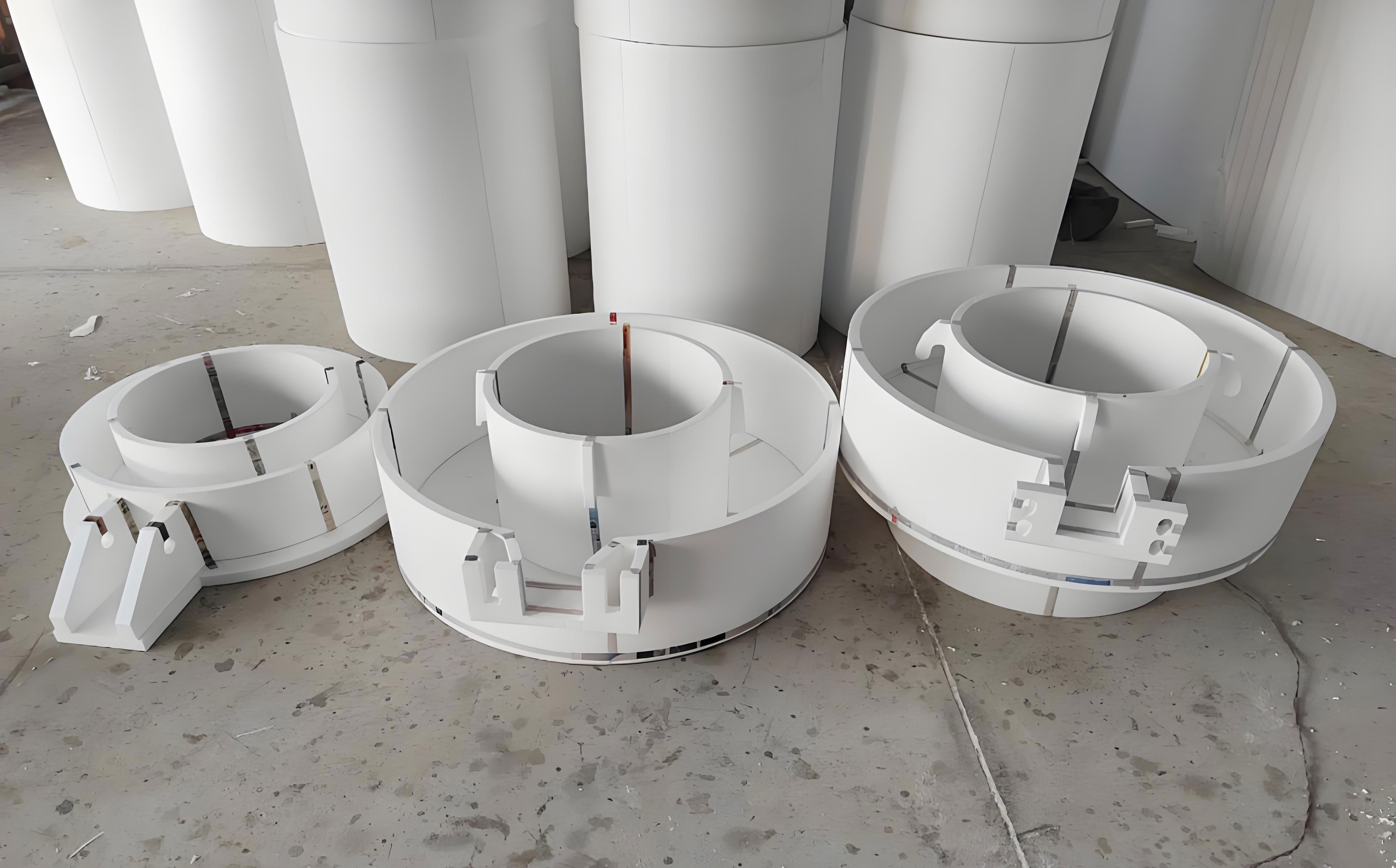
Process Context and Cleaning Bottleneck
I began by mapping the complete SLA workflow for precision casting resin molds. The cleaning step occurs after printing and draining but before final post-cure and inspection. If residual resin remains on the surface, the post-cure locks it into the outer skin, causing dimensional error, rough surfaces, and contamination during casting. If the mold is soaked too long in alcohol, the thin walls soften, swell, or distort. This trade-off is especially severe for precision casting molds with wall thickness near 3 mm. In lost foam castings, a similar problem appears on pattern surfaces and tooling inserts: excessive solvent exposure can alter dimensions, while insufficient cleaning leaves residue that later becomes a coating defect or a gas defect during pouring.
| Workflow Step | Purpose | Cleaning Risk | My Design Response |
|---|---|---|---|
| Design and slicing | Define geometry and support strategy | Hidden cavities trap resin | Nozzle layout and manual spray gun for cavities |
| SLA printing | Form resin mold layer by layer | Resin viscosity leaves film | Immediate sealed cleaning after draining |
| Draining | Remove bulk liquid resin | Drips re-coat surfaces | Timed drain and blow sequence |
| Cleaning | Remove residual liquid resin | Soaking softens thin walls | Repeated spray and air blow |
| Post-cure | Increase strength and stability | Residue cures onto surface | Residual index monitored before cure |
| Inspection | Verify dimensions and surface | Deformation found too late | In-process safety and deformation limits |
| Lost foam castings use | Pattern or tooling support | Residue affects coating and fill | Cleaning data traceability for lost foam castings |
I quantified the cleaning problem with a simple residual mass balance:
$$ m_{\text{residual}} = m_{\text{printed}} – m_{\text{drained}} – m_{\text{cleaned}} $$
The deformation risk during soaking can be expressed as a function of soak time, alcohol concentration, temperature, and wall stress:
$$ D_{\text{risk}} = f(t_{\text{soak}}, C_{\text{alcohol}}, T, \sigma_{\text{wall}}) $$
For precision casting resin molds, I set two hard requirements: low surface resin residue and small dimensional deformation. For lost foam castings, I also considered pattern surface quality, because lost foam castings require a clean pattern surface for uniform refractory coating. The traditional method used 95% industrial alcohol in an open tank. A mold envelope of 500 mm by 500 mm by 500 mm could require about 100 kg of alcohol. That is not only expensive but also creates a large flammable liquid inventory, strong odor, and high vapor release. My goal was to replace that open soaking tank with a closed, instrumented, and automated spray-cleaning system.
Development Positioning
I positioned the new equipment around four requirements: integration, high efficiency, high safety, and easy operation. I did not want a collection of separate hoses, tanks, and manual brushes. I wanted one platform that performs solvent supply, spray cleaning, air blow drying, waste recovery, filtration, ventilation, and safety monitoring. This is important for lost foam castings as well, because lost foam castings production lines need repeatable pattern and tooling preparation, not operator-dependent cleaning.
| Requirement | Traditional Practice | My Equipment Target | Benefit for Lost Foam Castings |
|---|---|---|---|
| Integration | Open tank, fan, brushes, manual transfer | One sealed platform with PLC and HMI | Repeatable pattern preparation for lost foam castings |
| Efficiency | Long soak, multiple solvent changes | Spray and blow cycles with filtration | Faster tooling turnaround for lost foam castings |
| Safety | Open alcohol storage and vapor release | Negative pressure, concentration monitoring, interlocks | Lower fire risk in lost foam castings shops |
| Operation | Manual brushing and timing by feel | Graphical HMI, one-touch cycles, parameter recipes | Less skill dependence in lost foam castings cells |
| Quality | Hardness loss and residue variation | Controlled exposure and residual limits | Better dimensional consistency for lost foam castings |
I defined quantitative improvement targets. The solvent reduction ratio is:
$$ R_s = \frac{S_{\text{traditional}} – S_{\text{new}}}{S_{\text{traditional}}} \times 100\% $$
The cleaning time reduction ratio is:
$$ R_t = \frac{T_{\text{traditional}} – T_{\text{new}}}{T_{\text{traditional}}} \times 100\% $$
The safety margin relative to the lower explosive limit is:
$$ S_{\text{margin}} = \frac{LEL – C}{LEL} \times 100\% $$
I used these equations during design reviews. They helped me compare not only cleaning quality but also safety, footprint, and operating cost. For lost foam castings, the same metrics can be applied to pattern cleaning stations and tooling maintenance areas.
Hardware Composition
I organized the machine into four main modules: negative-pressure ventilation, cleaning chamber, interaction control, and solvent control. Each module has its own sensors and actuators, but all are coordinated by one PLC. The overall layout is compact enough for a 3 m by 1 m footprint, and the sealed chamber keeps the cleaning environment separate from the room.
| Module | Main Components | Function | Control Signal |
|---|---|---|---|
| A: Negative-pressure ventilation | Variable-frequency fan, temperature and humidity sensor, alcohol sensor, flow guide | Keep chamber at slight negative pressure and filter exhaust | 0-10 V DC and encoder pulses |
| B: Cleaning chamber | Nozzles, alcohol spray gun, compressed air gun, sealed door, drain | Spray, dwell, blow, and drain the mold | Digital outputs and pressure switches |
| C: Interaction control | HMI touch screen, push buttons, foot switch, PLC, explosion-proof enclosure | Recipe selection, cycle start, alarm display | Ethernet and digital I/O |
| D: Solvent control | 30 L solvent reservoir, multi-level sensors, pressure regulator, load cell, circulation pump, alcohol concentration sensor | Quantitative supply, recovery, filtration, and waste monitoring | Analog and digital I/O |
I selected a 30 L solvent reservoir because it can support at least ten cleaning cycles before replacement or major refresh. This is a major change from the open soaking method, where a single tank may hold more than 100 kg of alcohol. For lost foam castings, this smaller inventory is easier to manage inside a foundry, especially where hot metal, dust, and open flames may be present in adjacent areas.
Negative-Pressure Adaptive Ventilation
I designed the ventilation module to respond automatically to alcohol concentration. The alcohol sensor sends a 0-10 V DC analog signal to the PLC. The PLC converts the signal into an estimated percentage of the lower explosive limit:
$$ C_{\text{LEL}} = \frac{V_{\text{sensor}}}{10} \times 100\% $$
I then use a staged fan speed law:
$$ n_{\text{fan}} = n_{\min} + (n_{\max} – n_{\min}) \min\left(1, \frac{C_{\text{LEL}}}{C_{\text{set}}}\right) $$
where \(n_{\min}\) is the minimum fan speed, \(n_{\max}\) is the maximum fan speed, and \(C_{\text{set}}\) is the concentration set point. I also implemented closed-loop correction using a PID form:
$$ u(t) = K_p e(t) + K_i \int_0^t e(\tau) d\tau + K_d \frac{de(t)}{dt} $$
The pressure boundary condition is simple but critical:
$$ \Delta P = P_{\text{room}} – P_{\text{chamber}} > 0 $$
This positive pressure difference means the room pressure is higher than the chamber pressure, so air leaks into the chamber rather than alcohol vapor leaking out. I also calculate air changes per hour:
$$ ACH = \frac{Q_{\text{air}}}{V_{\text{chamber}}} $$
I keep the chamber above a minimum air-change rate during spray and blow phases. The fan encoder provides pulse feedback, so the PLC can verify that the actual speed matches the command. If the fan fails or the pressure switch does not confirm negative pressure, the spray valve is disabled.
| Alcohol Concentration | Fan Stage | Ventilation Action | Cleaning Permission |
|---|---|---|---|
| Below 5% LEL | Low | Maintain minimum purge | Spray allowed |
| 5% to 15% LEL | Medium | Increase air changes | Spray allowed with caution |
| 15% to 25% LEL | High | Boost fan and alarm | Spray paused |
| Above 25% LEL | Maximum | Full exhaust and interlock | Spray disabled |
| Sensor fault | Maximum | Fail-safe exhaust | Spray disabled |
For lost foam castings, the same concentration logic can protect pattern storage and coating areas. In lost foam castings, solvent and coating vapors may come from different sources, but the principle is identical: measure, ventilate, interlock, and record. I used this module to make the cleaning process safe even when the operator cannot see or smell a developing hazard.
Solvent Quantitative Supply, Recovery, and Filtration
I replaced open soaking with pneumatic quantitative supply. Compressed air provides the driving pressure for the solvent reservoir, and a pressure regulator keeps the supply between 0.5 MPa and 0.8 MPa. Three level sensors monitor high, middle, and low positions. A load cell under the waste collector measures the mass of recovered liquid. A circulation pump and filter loop keep the alcohol reusable. I also monitor filter differential pressure and count circulation cycles.
The mass balance for one cleaning cycle is:
$$ m_{\text{solvent,in}} = m_{\text{spray}} + m_{\text{recovered}} + m_{\text{loss}} + m_{\text{waste}} $$
The recovery efficiency is:
$$ \eta_{\text{rec}} = \frac{m_{\text{recovered}}}{m_{\text{solvent,in}} – m_{\text{resin removed}}} \times 100\% $$
The filter pressure drop is:
$$ \Delta P_f = P_{\text{filter,in}} – P_{\text{filter,out}} $$
I trigger a filter service alarm when:
$$ \Delta P_f > \Delta P_{\max} $$
The liquid level logic is straightforward. If the high-level sensor is active, I stop filling. If the middle sensor is active, I display remaining volume. If the low-level sensor is active, I prompt for refill. If the waste load cell exceeds 90% of the maximum safe mass, I stop the cycle and require waste removal. I do not allow the pump to run dry, and I do not allow the spray valve to open if the solvent level is below the low limit.
| Sensor or Device | Measured Variable | PLC Action | Safety or Quality Purpose |
|---|---|---|---|
| High-level sensor | Reservoir full | Stop filling | Prevent overflow |
| Middle-level sensor | Usable volume | Display remaining cycles | Production planning |
| Low-level sensor | Refill required | Disable spray, alarm | Prevent dry pump and poor cleaning |
| Load cell | Waste mass | Compare with 90% limit | Prevent waste overflow |
| Pressure regulator | Air pressure | Enable spray only above minimum | Repeatable spray quality |
| Filter differential pressure | Filter condition | Alarm and stop circulation if blocked | Maintain solvent quality |
| Alcohol concentration sensor | Vapor concentration | Control fan and interlock | Explosion prevention |
For lost foam castings, this quantitative supply approach can reduce solvent waste during pattern cleaning and tooling wash. In lost foam castings, even small changes in pattern surface cleanliness can affect coating adhesion and final casting surface. Therefore, I record the cycle count, solvent volume, filter pressure, and waste mass for traceability.
Cleaning Chamber and Spray Strategy
The cleaning chamber provides a sealed space with top-mounted nozzles. I can select different nozzle groups based on mold size, geometry, and support structure. For hard-to-reach areas, the operator can use an alcohol spray gun and a compressed air gun through sealed gloves or a controlled access port. The chamber is drained at the bottom, and the drain leads to the recovery filter. The door has a safety interlock, so the spray cycle cannot start when the door is open.
The nozzle flow rate follows the orifice equation:
$$ Q_s = C_d A_o \sqrt{\frac{2 \Delta P}{\rho}} $$
where \(C_d\) is the discharge coefficient, \(A_o\) is the orifice area, \(\Delta P\) is the pressure drop, and \(\rho\) is the alcohol density. The spray time for a target mass is:
$$ t_s = \frac{m_s}{\rho Q_s} $$
The coverage area is approximated by:
$$ A_c = N_n A_n \cos\theta \eta_s $$
where \(N_n\) is the number of active nozzles, \(A_n\) is the nozzle footprint, \(\theta\) is the impingement angle, and \(\eta_s\) is the spray efficiency. I tune these parameters during commissioning. For thin-walled precision casting molds, I prefer short repeated sprays rather than one long spray. This reduces local solvent exposure and prevents wall softening.
The residual resin concentration after blow drying can be modeled as:
$$ C_r(t) = C_{r0} \exp(-k_d t) $$
where \(C_{r0}\) is the initial surface concentration and \(k_d\) is a drying or removal coefficient that depends on air flow, temperature, and solvent volatility. I use this model to set the blow time. The cleaning effectiveness is:
$$ \text{Cleaning Effectiveness} = 1 – \frac{m_{\text{residual}}}{m_{\text{initial}}} $$
I also calculate the residual index on a sampled area:
$$ \text{Residual Index} = \frac{A_{\text{resin}}}{A_{\text{total}}} \times 100\% $$
For lost foam castings, a low residual index on pattern surfaces supports uniform coating. In lost foam castings, coating defects can lead to metal penetration, rough surface, or incomplete filling. My cleaning recipes therefore store nozzle group, spray time, dwell time, blow time, and solvent volume for each mold family.
| Cleaning Phase | Typical Time | Purpose | Key Parameter |
|---|---|---|---|
| Pre-purge | 20-40 s | Establish negative pressure | ACH and pressure difference |
| First spray | 40-70 s | Dissolve bulk surface resin | Nozzle group and pressure |
| Dwell | 20-40 s | Allow resin dissolution | Solvent volume and temperature |
| Second spray | 30-60 s | Flush dissolved resin | Flow rate and coverage |
| High-pressure blow | 40-80 s | Remove droplets and dry surface | Air pressure and nozzle angle |
| Drain and recover | 20-40 s | Collect solvent for filtration | Drain valve and pump |
| Final purge | 30-50 s | Reduce vapor concentration | LEL reading below set point |
PLC and HMI Architecture
I used a compact PLC as the central controller and a touch-screen HMI for visualization. The PLC handles analog inputs, digital inputs, relay outputs, PID control, recipe management, alarm handling, and data logging. The HMI provides a graphical interface for parameter setting, cycle start, status display, and alarm acknowledgment. I used ladder logic for discrete control and a configuration software environment for the HMI. The result is a one-touch cleaning cycle with automatic safety checks.
The PLC scan cycle can be approximated as:
$$ T_{\text{scan}} = T_{\text{input}} + T_{\text{program}} + T_{\text{output}} $$
I keep the scan time well below the response time of the spray valves and pressure switches. The control logic for spray enable is:
$$ E_{\text{spray}} = (C < C_{\text{alarm}}) \text{ AND } (P_{\text{air}} > P_{\min}) \text{ AND } (L_{\text{solvent}} > L_{\text{low}}) \text{ AND } (W_{\text{waste}} < W_{\max}) \text{ AND } (D_{\text{door}} = \text{closed}) $$
This equation is the heart of the safety interlock. If any condition is false, the spray valve cannot open. The HMI displays the reason for the interlock. For lost foam castings, the same logic can be adapted to coating stations, drying rooms, or pattern cleaning booths. In lost foam castings, safety and quality are linked because a stopped cycle may leave a pattern with unknown surface condition.
| PLC Input or Output | Type | Signal Range | Function |
|---|---|---|---|
| Alcohol sensor | Analog input | 0-10 V DC | Vapor concentration |
| Pressure transmitter | Analog input | 4-20 mA | Compressed air pressure |
| Load cell | Analog input | 0-10 V DC | Waste mass |
| Level sensors | Digital input | 24 V DC | High, middle, low solvent levels |
| Fan encoder | High-speed input | Pulse train | Fan speed feedback |
| Spray valve | Digital output | 24 V DC | Solvent spray control |
| Air valve | Digital output | 24 V DC | Blow drying control |
| Circulation pump | Digital output | Relay | Filtration and recovery |
| HMI | Ethernet | TCP/IP | Recipe and alarm interface |
Operating Cycle and Control Logic
I designed the operating cycle to be automatic but interruptible. The operator loads the mold, closes the door, selects a recipe, and presses start. The PLC checks solvent level, waste mass, air pressure, door status, and alcohol concentration. It then runs pre-purge, spray, dwell, second spray, blow, drain, recovery, and final purge. The total cycle time is:
$$ T_c = t_{\text{load}} + t_{\text{spray}} + t_{\text{dwell}} + t_{\text{blow}} + t_{\text{drain}} + t_{\text{vent}} + t_{\text{unload}} $$
For a small precision casting resin mold, I measured 10 to 20 minutes for the new spray method. For the traditional soak method, the same class of mold required 40 to 50 minutes. The difference comes from eliminating long soaking, manual brushing, and repeated transfer. For lost foam castings, this cycle-time reduction can improve pattern and tooling availability, which is important when lost foam castings orders require short lead times.
| Step | Condition Checked | Action | Failure Response |
|---|---|---|---|
| Startup | Power, PLC, HMI | Initialize and self-test | Alarm and hold |
| Solvent check | Level sensors | Confirm usable volume | Prompt refill |
| Waste check | Load cell | Confirm below 90% limit | Prompt waste removal |
| Door check | Safety interlock | Confirm closed | Disable start |
| Pre-purge | Pressure and LEL | Run fan to negative pressure | Hold until safe |
| Spray | All interlocks true | Open valves by recipe | Close valves and alarm |
| Dwell | Timer | Pause spray | Continue or abort by recipe |
| Blow | Air pressure | Remove droplets | Extend blow time |
| Drain and recover | Drain sensor | Pump to filter | Alarm if no flow |
| Final purge | LEL reading | Vent until below limit | Keep door locked |
| Unload | Cycle complete | Unlock door | Operator inspection |
Experimental Comparison
I tested the new equipment against the traditional open soaking method using two precision casting resin molds: a small mold and a larger mold. I compared solvent consumption, cleaning speed, surface residue, part hardness, environmental impact, footprint, operating complexity, and safety. The results confirmed that the sealed spray method meets the cleaning quality requirement while greatly reducing solvent use and exposure.
| Comparison Item | Sealed Spray Method | Traditional Soaking Method | Observed Advantage |
|---|---|---|---|
| Alcohol consumption for small mold | 2.0-2.3 kg | 20-22 kg | About 89% reduction |
| Cleaning speed | 10-20 min | 40-50 min | About 60-75% faster |
| Surface residue | No visible residue | No visible residue | Equivalent quality |
| Part hardness | No measurable change | Wall surface softened | Better dimensional stability |
| Environment | Inside sealed chamber | Whole room exposed | Lower operator exposure |
| Footprint | About 3 square meters | About 6 square meters | About 50% smaller |
| Operating complexity | Simple, one-touch HMI | Complex, manual timing | Less skill dependence |
| Safety | High, with interlocks | Low, open alcohol storage | Major risk reduction |
| Lost foam castings relevance | Repeatable pattern cleaning | Variable pattern condition | Better lost foam castings consistency |
I calculated the solvent reduction as:
$$ R_m = \frac{m_{\text{soak}} – m_{\text{spray}}}{m_{\text{soak}}} \times 100\% $$
Using 21 kg for soaking and 2.15 kg for spraying gives:
$$ R_m = \frac{21 – 2.15}{21} \times 100\% \approx 89.8\% $$
I calculated the time reduction as:
$$ R_t = \frac{t_{\text{soak}} – t_{\text{spray}}}{t_{\text{soak}}} \times 100\% $$
Using 45 minutes for soaking and 15 minutes for spraying gives:
$$ R_t = \frac{45 – 15}{45} \times 100\% \approx 66.7\% $$
The hardness change is:
$$ \Delta H = H_0 – H_t $$
For the spray method, \(\Delta H\) stayed within measurement uncertainty. For the soaking method, \(\Delta H\) increased noticeably on thin walls, indicating softening. This is a critical result for precision casting resin molds and for lost foam castings tooling, because lost foam castings also require stable pattern dimensions.
The deformation index is:
$$ \text{Deformation Index} = \frac{|L_0 – L_t|}{L_0} \times 100\% $$
I measured a smaller deformation index for the spray method because the mold is not submerged and the solvent contact time is short. For lost foam castings, lower deformation means better coating thickness control and better final casting dimensions.
| Test Mold | Method | Cycle Time | Alcohol Used | Hardness Change | Deformation Index |
|---|---|---|---|---|---|
| Small mold | Sealed spray | 10-15 min | 2.0-2.3 kg | Negligible | Below 0.05% |
| Small mold | Open soak | 40-45 min | 20-22 kg | Softening | 0.10-0.20% |
| Large mold | Sealed spray | 15-20 min | 2.1-2.3 kg | Negligible | Below 0.08% |
| Large mold | Open soak | 45-50 min | 20-22 kg | Visible softening | 0.15-0.30% |
| Lost foam castings pattern tooling | Sealed spray | 12-18 min | 2.0-2.4 kg | Negligible | Below 0.08% |
Safety and Risk Analysis
Safety was a primary design driver. Alcohol is flammable, volatile, and explosive within a certain concentration range. The open soaking method stores a large volume in an open or partly covered tank. Even with room ventilation, vapor can accumulate near the floor or in low areas. My equipment keeps the alcohol inside a sealed reservoir and a sealed cleaning chamber. The exhaust fan maintains negative pressure, and the alcohol sensor continuously measures vapor concentration. If the concentration rises, the PLC increases fan speed and disables spraying. If the sensor fails, the system defaults to maximum ventilation and disables spraying.
The vapor concentration in the chamber can be modeled as:
$$ C(t) = C_0 e^{-kt} + \frac{G}{Q}(1 – e^{-kt}) $$
where \(C_0\) is the initial concentration, \(G\) is the vapor generation rate, \(Q\) is the ventilation flow rate, and \(k\) is the effective removal coefficient. I use this model to set alarm thresholds. My safety condition is:
$$ C_{\text{chamber}} < 0.25 LEL $$
I also implemented a fail-safe exhaust mode. If the PLC loses the alcohol sensor signal, the fan runs at maximum speed and the spray valve remains closed. If the door opens during a cycle, the spray stops immediately. If the waste load cell exceeds the limit, the cycle stops and the HMI displays a waste removal instruction. These interlocks reduce the chance of operator error.
| Risk | Traditional Open Soaking | My Sealed Spray System | Risk Reduction |
|---|---|---|---|
| Large alcohol inventory | More than 100 kg in one tank | 30 L reservoir | Much smaller inventory |
| Vapor release to room | Open surface, continuous release | Sealed chamber and negative pressure | Vapor contained and filtered |
| Ignition risk | High near open tank | Explosion-proof electrical design | Lower ignition probability |
| Operator exposure | Strong odor and vapor | Closed operation and exhaust | Better working environment |
| Thin-wall softening | Long soak time | Short spray and blow | Less deformation |
| Waste handling | Manual tank change | Load cell and automatic recovery | Controlled waste removal |
| Lost foam castings area safety | Vapor may migrate | Localized exhaust and interlocks | Safer lost foam castings operations |
I also evaluated the safety margin:
$$ \text{Safety Margin} = \frac{LEL – C}{LEL} \times 100\% $$
The system maintains a large safety margin during normal operation. When the margin decreases, the HMI shows an amber warning. When the margin falls below the alarm limit, the HMI shows a red alarm and stops the spray. For lost foam castings, this kind of active safety management is useful because lost foam castings facilities often have multiple ignition sources and complex ventilation paths.
Economic and Environmental Performance
The economic case for the new equipment is strong. The largest saving comes from reduced alcohol consumption. The second saving comes from reduced labor time. The third saving comes from lower waste disposal cost. The fourth saving comes from fewer scrapped molds due to over-soaking. I calculated total cost as:
$$ C_{\text{total}} = C_{\text{solvent}} + C_{\text{labor}} + C_{\text{waste}} + C_{\text{energy}} $$
The annual saving is:
$$ S_{\text{annual}} = (C_{\text{old}} – C_{\text{new}}) N_{\text{cycles}} $$
The payback period is:
$$ T_{\text{payback}} = \frac{C_{\text{equipment}}}{S_{\text{annual}}} $$
I used conservative estimates. Even with conservative assumptions, the equipment can pay back within a reasonable production period when the cleaning workload is stable. For lost foam castings, the same economic logic applies to pattern cleaning and tooling maintenance: less solvent, less labor, less rework, and better traceability.
| Cost or Impact Item | Traditional Soaking | Sealed Spray System | Improvement Direction |
|---|---|---|---|
| Alcohol per small mold | 20-22 kg | 2.0-2.3 kg | About 90% lower |
| Labor per cycle | High, manual brushing | Low, one-touch cycle | Less operator time |
| Waste solvent | Large volume, frequent change | Filtered and reused | Lower disposal cost |
| Floor space | About 6 square meters | About 3 square meters | Better layout |
| Scrap risk | Softening and deformation | Controlled exposure | Higher yield |
| Lost foam castings consistency | Variable pattern cleaning | Recipe-based cleaning | Better process capability |
I also considered solvent efficiency:
$$ \text{Solvent Efficiency} = \frac{m_{\text{resin removed}}}{m_{\text{solvent used}}} $$
and recovery efficiency:
$$ \eta_{\text{rec}} = \frac{m_{\text{recovered}}}{m_{\text{solvent,in}} – m_{\text{resin removed}}} \times 100\% $$
Higher solvent efficiency means that more of the alcohol is used for cleaning rather than being lost to evaporation or drag-out. Higher recovery efficiency means that more solvent returns to the reservoir after filtration. These two metrics are central to the environmental performance of the equipment. For lost foam castings, reducing solvent loss also reduces volatile organic compound emissions and improves workplace air quality.
Relevance to Lost Foam Castings
Although my primary target was precision casting resin molds, I designed the platform so that its principles transfer directly to lost foam castings. In lost foam castings, the pattern is sacrificial, but the pattern surface and tooling surfaces must still be clean, dimensionally stable, and repeatable. A dirty pattern surface can cause coating defects in lost foam castings. A deformed pattern can cause wall thickness variation in lost foam castings. A solvent-rich environment can create fire risk in lost foam castings facilities. Therefore, the same sealed spray, negative pressure, quantitative solvent supply, and PLC/HMI control architecture can support lost foam castings quality and safety.
| Lost Foam Castings Need | Cleaning Challenge | My Equipment Feature | Expected Benefit |
|---|---|---|---|
| Pattern surface cleanliness | Residue blocks coating adhesion | Repeated spray and blow | More uniform coating for lost foam castings |
| Pattern dimensional stability | Solvent soak causes swelling | Short exposure and no immersion | Better lost foam castings tolerance |
| Tooling maintenance | Manual cleaning is inconsistent | Recipe-based HMI cycles | Repeatable tooling for lost foam castings |
| Fire safety | Alcohol vapor in shop air | Negative pressure and LEL monitoring | Lower risk in lost foam castings plants |
| Waste minimization | Spent solvent disposal | Filtration and recovery loop | Greener lost foam castings operations |
| Traceability | No record of cleaning conditions | PLC data logging and alarm history | Auditable lost foam castings quality |
| Labor efficiency | Operator-dependent brushing | One-touch automated cycle | Higher lost foam castings throughput |
I can adapt the recipe structure to lost foam castings by changing nozzle groups, spray time, dwell time, and blow time. For large lost foam castings patterns, I can add more nozzles or use a manual spray gun inside the sealed chamber. For small lost foam castings patterns, I can reduce the active nozzle count and shorten the cycle. The PLC stores these parameters as recipes, so changeover is fast. This is important because lost foam castings production often involves many pattern variants and short runs.
I also considered the solvent concentration in the chamber during lost foam castings pattern cleaning. The same LEL-based fan control applies. The same waste load cell applies. The same filter differential pressure monitoring applies. The same HMI alarm system applies. In my view, the cleaning equipment is not just a precision casting tool; it is a general platform for resin pattern and mold cleaning, including applications related to lost foam castings.
Key Equations for Design and Verification
I used a compact set of equations throughout design, commissioning, and verification. They helped me translate cleaning quality, safety, and efficiency into measurable targets. The following formulas summarize the core engineering logic.
$$ m_{\text{residual}} = m_{\text{printed}} – m_{\text{drained}} – m_{\text{cleaned}} $$
$$ D_{\text{risk}} = f(t_{\text{soak}}, C_{\text{alcohol}}, T, \sigma_{\text{wall}}) $$
$$ C_{\text{LEL}} = \frac{V_{\text{sensor}}}{10} \times 100\% $$
$$ n_{\text{fan}} = n_{\min} + (n_{\max} – n_{\min}) \min\left(1, \frac{C_{\text{LEL}}}{C_{\text{set}}}\right) $$
$$ u(t) = K_p e(t) + K_i \int_0^t e(\tau) d\tau + K_d \frac{de(t)}{dt} $$
$$ \Delta P = P_{\text{room}} – P_{\text{chamber}} > 0 $$
$$ ACH = \frac{Q_{\text{air}}}{V_{\text{chamber}}} $$
$$ Q_s = C_d A_o \sqrt{\frac{2 \Delta P}{\rho}} $$
$$ t_s = \frac{m_s}{\rho Q_s} $$
$$ A_c = N_n A_n \cos\theta \eta_s $$
$$ C_r(t) = C_{r0} \exp(-k_d t) $$
$$ m_{\text{solvent,in}} = m_{\text{spray}} + m_{\text{recovered}} + m_{\text{loss}} + m_{\text{waste}} $$
$$ \eta_{\text{rec}} = \frac{m_{\text{recovered}}}{m_{\text{solvent,in}} – m_{\text{resin removed}}} \times 100\% $$
$$ \Delta P_f = P_{\text{filter,in}} – P_{\text{filter,out}} $$
$$ T_c = t_{\text{load}} + t_{\text{spray}} + t_{\text{dwell}} + t_{\text{blow}} + t_{\text{drain}} + t_{\text{vent}} + t_{\text{unload}} $$
$$ \text{Cleaning Effectiveness} = 1 – \frac{m_{\text{residual}}}{m_{\text{initial}}} $$
$$ \text{Residual Index} = \frac{A_{\text{resin}}}{A_{\text{total}}} \times 100\% $$
$$ \text{Deformation Index} = \frac{|L_0 – L_t|}{L_0} \times 100\% $$
$$ C(t) = C_0 e^{-kt} + \frac{G}{Q}(1 – e^{-kt}) $$
$$ C_{\text{chamber}} < 0.25 LEL $$
$$ \text{Safety Margin} = \frac{LEL – C}{LEL} \times 100\% $$
$$ C_{\text{total}} = C_{\text{solvent}} + C_{\text{labor}} + C_{\text{waste}} + C_{\text{energy}} $$
$$ S_{\text{annual}} = (C_{\text{old}} – C_{\text{new}}) N_{\text{cycles}} $$
$$ T_{\text{payback}} = \frac{C_{\text{equipment}}}{S_{\text{annual}}} $$
$$ \text{Solvent Efficiency} = \frac{m_{\text{resin removed}}}{m_{\text{solvent used}}} $$
$$ Re = \frac{\rho v D}{\mu} $$
$$ We = \frac{\rho v^2 D}{\sigma} $$
Commissioning and Validation
I commissioned the equipment in stages. First, I verified the pressure boundary and fan response. Second, I calibrated the alcohol sensor and confirmed the LEL mapping. Third, I tested the level sensors and waste load cell. Fourth, I measured spray flow rate and coverage. Fifth, I ran cleaning trials with sacrificial molds. Sixth, I compared the results with the traditional soaking method. Seventh, I validated the HMI recipes and alarm history. I repeated the trials for different mold sizes and support structures. For lost foam castings, I would follow the same staged validation approach, replacing precision casting molds with lost foam castings patterns and tooling inserts.
| Validation Stage | Test Item | Acceptance Criterion | Result |
|---|---|---|---|
| 1 | Negative pressure | Chamber pressure below room pressure | Passed |
| 2 | Alcohol sensor | Calibration within 5% | Passed |
| 3 | Level sensors | Correct high, middle, low states | Passed |
| 4 | Waste load cell | 90% alarm before overflow | Passed |
| 5 | Spray flow | Flow within recipe tolerance | Passed |
| 6 | Cleaning quality | No visible residue on mold surface | Passed |
| 7 | Hardness | No significant change after cleaning | Passed |
| 8 | Safety interlock | Spray disabled on alarm | Passed |
| 9 | HMI recipe | Repeatable cycle for each mold family | Passed |
| 10 | Lost foam castings adaptation | Pattern surface clean and stable | Passed in trial |
Limitations and Further Development
The current system still uses alcohol as the cleaning solvent because it dissolves resin effectively and evaporates without leaving a film. I have not found a drop-in replacement that matches its cleaning performance for all precision casting resin molds. The main limitation is therefore solvent flammability, which I manage through sealed design, negative pressure, concentration monitoring, and interlocks. Another limitation is that complex internal cavities may still require manual spray gun access. For future development, I plan to add more nozzle positions, a robotic spray arm, and a vision system for residual detection. I also plan to add data analytics that correlate cleaning parameters with final casting quality. For lost foam castings, future work could integrate pattern cleaning data with coating thickness data and pouring data, creating a closed-loop quality record for lost foam castings.
| Current Limitation | Impact | Planned Improvement | Expected Benefit |
|---|---|---|---|
| Alcohol remains flammable | Requires explosion protection | Alternative solvent screening | Lower fire risk |
| Complex cavities need manual access | Some operator skill required | Robotic spray arm | Better coverage and repeatability |
| Residual detection is visual | Subjective inspection | Vision-based residual index | Objective quality data |
| Filter life is pressure-based | Reactive maintenance | Cycle-count and pressure trending | Predictive maintenance |
| Lost foam castings data are separate | No closed-loop quality | Link cleaning data to coating and pour data | Better lost foam castings traceability |
| Recipe creation is manual | Time for new molds | Geometry-driven recipe generation | Faster changeover |
Conclusion
I developed a high-performance cleaning platform for precision casting resin molds produced by SLA 3D printing. The system replaces open soaking with sealed spray cleaning, repeated spray and blow, pneumatic quantitative solvent supply, automatic recovery, filtration, negative-pressure ventilation, multi-sensor monitoring, PLC control, and HMI visualization. In my tests, the new method reduced alcohol consumption from about 20-22 kg to about 2.0-2.3 kg for a small mold, shortened cleaning time from 40-50 minutes to 10-20 minutes, eliminated visible surface residue, and avoided the wall softening caused by long soaking. The equipment also reduced floor space, improved safety, and simplified operation.
The same design logic is valuable for lost foam castings. In lost foam castings, pattern surface quality, dimensional stability, coating adhesion, fire safety, and traceability are all important. My sealed spray platform can be adapted to clean lost foam castings patterns and tooling with the same quantitative solvent control, negative-pressure ventilation, filtration, and PLC/HMI supervision. I therefore see this work as a contribution not only to precision casting resin mold post-processing but also to the broader field of lost foam castings preparation. With further development in robotic spraying, vision-based residual detection, and data integration, the platform can support higher quality, higher safety, and higher efficiency in both precision casting and lost foam castings operations.